FINAL INDEPENDENT PROJECT
MODELLING OF DOOSAN CONCEPT-X EXCAVATOR BY USING SOLIDWORKS
ABSTRACT:
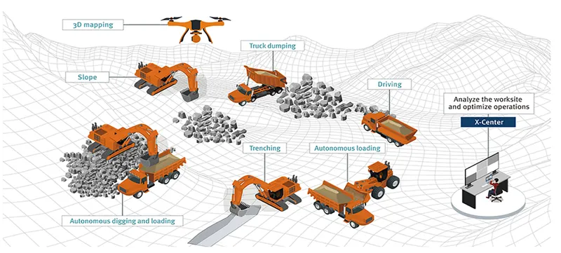
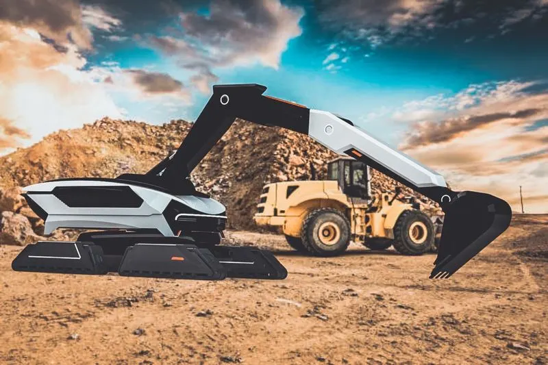
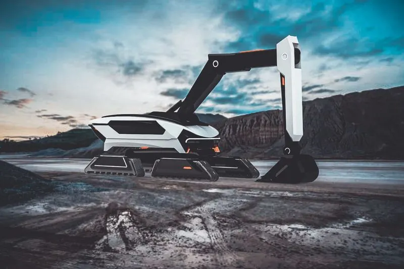
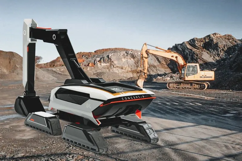
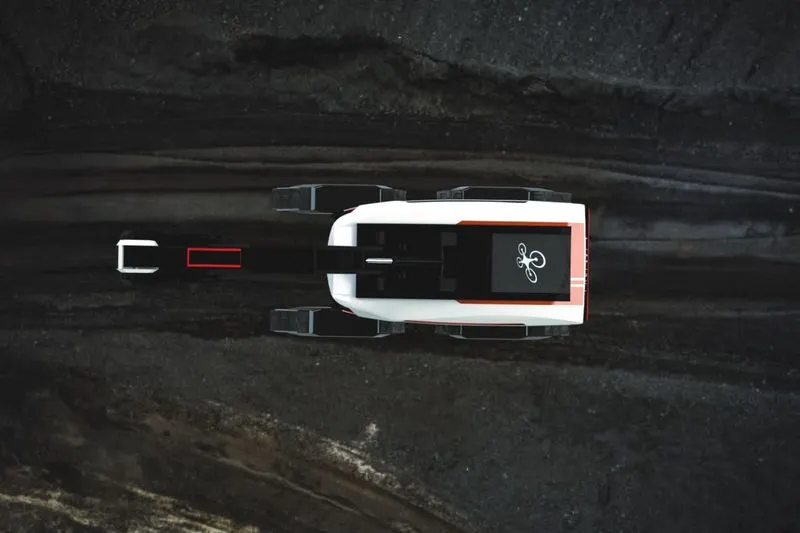
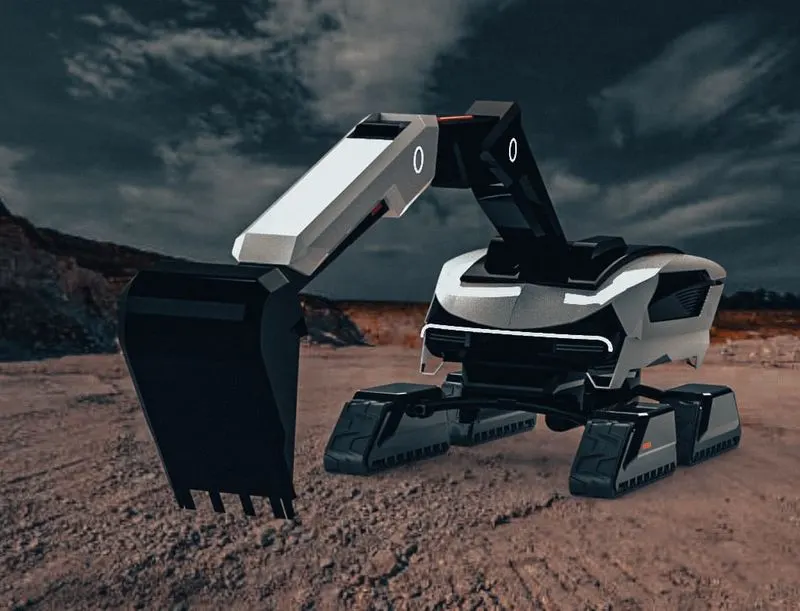
Concept-X is a solution based on technology optimized for future construction sites, such as automated construction site surveying tasks using drones, unmanned automation of equipment, and remote control based on 5G communication. Concept-X will satisfy customer needs and create new added value by increasing productivity and reducing costs and risks based on accurate, fast work at the construction site.
OBJECTIVE:
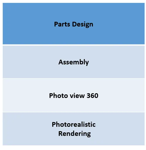
To create a 3D model of the EXCAVATOR parts and assemble of that parts and finally to creat photorealistic rendering image by using different tools & commends in solidworks.
DESIGN METHODOLAGY:
DESCRIPTION OF TOOLS:
SKETCH:
The sketch is the basic for a 3D model sketch is used to draw the dimensional representation of the model with respect to the plane in solidworks. There are different sketch option availabel to create a sketch, these are known as entities.The following are entities available in the solid works-line, arc, spline, circle, rectangle, ellipse, polygon and slot .
OFFSET:
Copy a sketch entity to a specified distance from the original entity.
EXTRUDE:
Base Extrudes a sketch or selected sketch contours in one or two directions to create a solid feature.
MIRROR ENTITIES:
Create a reflected copy of a desired entity about a centerline or axis.
LINEAR SKETCH PATYTERN:
Pattern a sketch entity either horizontally, vertically, or angled. Under the property manager the user can specify the distance between the original sketch entity and the patterned copy, the number of instances, and an angle the pattern will
FILLET :
Fillet Creates a rounded internal or external face along one or more edges in solid or surface feature.
LOFTED BOSS:
Base Adds material between two or more profiles to create a solid feature.
DOME:
Dome is generally applied to give some shape to the flat faces.Select one or more planar or non planar faces
EXTRUDE CUT:
Extrude cut is another feature which helps to remove materials from the 3D modellt is just the opposite to extrudie base feature because it cuts a sketch profile while extruding.cut in both directions and mainly used for creatingholes.channels,slots
SPLIT:
In solidworks, split line tool is used to project an entity onto other surface or curved or planar face
TRIM ENTITIES:
The trim tool type is selected based on the entities want to trim or extend. All trim types are available with 2D sketches on 3D planes.
REVOLVE:
To create a revolve feature, create a sketch that contains one or more profiles and a centerline, line, or edge to use as the axis around which the feature revolve or we can turn on the temporary axis and select one of the following revolve tools.
DYNAMIC MIRROR:
Dynamic mirror is an important tool in solid works. As you sketch the entities, they are mirrored about the pre selecter sketch entity.
COMBINE:
It is used to define the thickness of thin and thick shell elements. Combine is the type of feature available in solidworks to manually combine the two bodies into a single one
SHELL:
It is used to define the thickness of thin and thick shell elements.
BLOCKS:
You can make save, edit and insert blocks for drawing items and sketch entities that you use often, such as standard notes title blocks, label positions, and so on.
PATTERNS:
The curve driven pattern tool allows you to create patterns along a planar or 3D curve pattern on an open curve on a closed curve, such as a circle. In the cahin part curve driven pattern used.
CHAMBER:
A cut on the edge or corner of something that makes it slope slightly rather than being perfectly square
LINEAR PATTERN:
It is also more like a circular pattern. The feature /bodies are patterned linearly. Pattern is a kind tool like a may available in autocad.
CIRCULAR PATTERN:
It is used to create a pattern of the sporks and the pattern available in the tyre. Also it is used to create holes in the discs of the front wheel. The parent bodies/ features are used to create a different number of instances required to create the pattern circularly.
MOVE:
It is used to move the body from one place to other place in the fork.
MIRROR:
By using mirror face with a mid plane selected only the chosen face within the revolve will be mirrored. Mirroring bodies can be used whether in a single or multi body part and allows you to select solid geometry instead of the feature and face in a body.
PROJECT CURVE:
It is the kind of 3D curve which is projected on the basis of the two different 2D sketches.
SWEEP:
With the sweep feature we can create a shape by moving a 2D sketch profile along a 2D or 3D sketch path
LOFT SURFACE:
The surface generated by multiple 3D curves or existing edges creating a smooth tangency between the selected curves.
FILLED SURFACE:
The filled surface feature constructs a surface patch with any number of side, within a boundary defined by existing model edges, sketches, or curves including composite curve.
SUFACE TRIM:
Primarily used to cut away material from a surface, and provide two modes: standard and mutual
SURFACE KNIT:
It is used to knit the two free edge / open edge of the surface together. also it reduces the gap between the two edges of the surface
SWEEP SURFACE:
The surface that are generated from a section curve positioned along a path.
PARTS TO BE MODELLED FOR EXCAVATER:
TRACK :
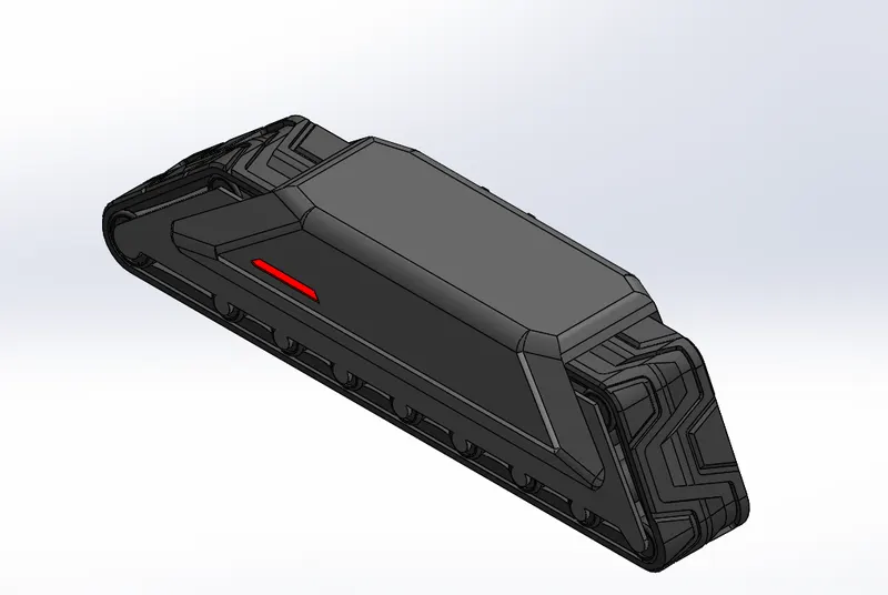
Continuous track is a system of vehicle propulsion used in tracked vehicles, running on a continuous band of treads or track plates driven by two or more wheels. The large surface area of the tracks distributes the weight of the vehicle better than steel or rubber tyres on an equivalent vehicle, enabling continuous tracked vehicles to traverse soft ground with less likelihood of becoming stuck due to sinking.
Modern continuous tracks can be made with soft belts of synthetic rubber, reinforced with steel wires, in the case of lighter agricultural machinery. The more common classical type is a solid chain track made of steel plates (with or without rubber pads), also called caterpillar tread or tank tread, which is preferred for robust and heavy construction vehicles and military vehicles.
FRAME:
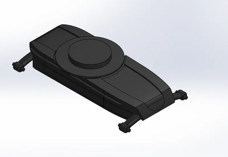
An excavator undercarriage frame is made to reduce the amount of machining necessary for supporting a swing bearing and ring gear on which an upper swing platform including the cab and operator's platform are mounted.
SUPERSTRUCTURE:
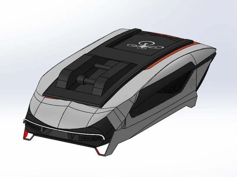
Superstructure tilt-rotators have only been used in Nordic countries but now they are becoming popular globally. It is a connection between the end of the arm and the attachment tool that enables it to rotate 360 degrees and tilt +-45 degrees. A grapple function is also included. This enables the excavator to complete a broad range of tasks in various conditions.
HYDRAULIC BREAKER:
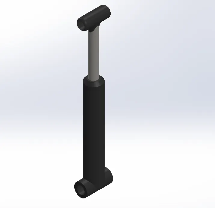
Hydraulic breaker attachments (also known as hammers) are used to break or demolish structures, pavements, or other solid surfaces. This can be used to make the demolition quicker.
BOOM:
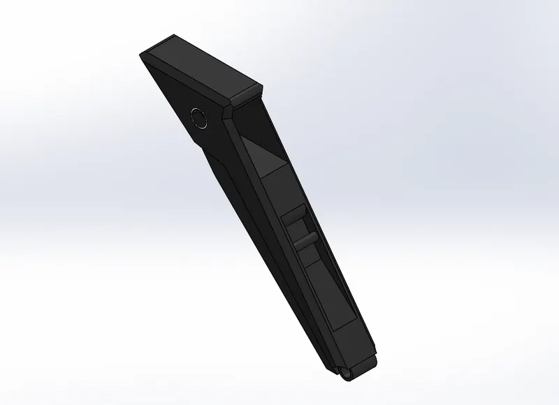
The primary purpose of boom swing is for offset digging around obstacles or along foundations, walls or forms. A secondary use is cycling in areas too narrow for cab rotation. Independent boom swing is one of the major advantages of a compact excavator over other excavation equipment.
ARMS:
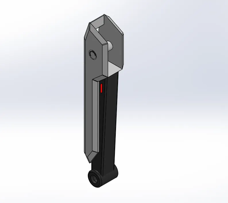
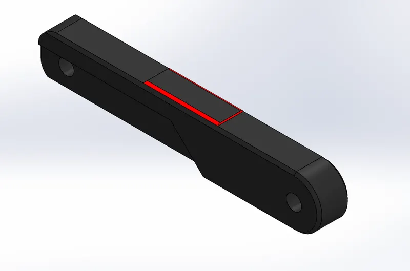
The boom is the angled arm that is attached to the excavator itself and the arm is pinned to the boom. The arm is sometimes called the dipper or stick. On an excavator, the house includes the cab, counterweights, fuel tank, hydraulic tank, and the engine.
THE EXCAVATOR ARM It is composed of three hydraulic pistons that operate in tandem with steel piston arms. The two main sections and bucket loader are connected by means of a hinge. The extension of the first piston widens the section at the same time as increases in girth, providing further reach for the operator.
BUCKET:
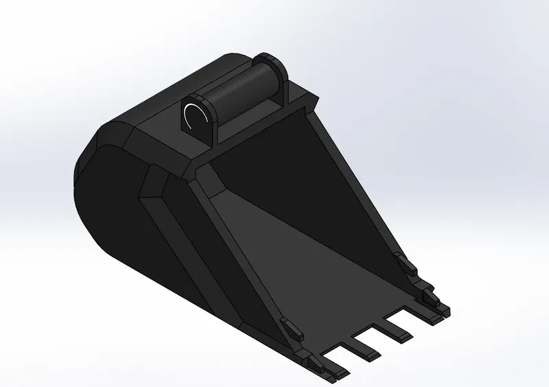
This is the most common tool for excavators. Different types of buckets have different purposes: a slim bucket is typically used for digging, while wide or smooth ones are ideal for scooping or carrying objects.
ASSEMBLY OF EXCAVATER:
Initially, the frame part is inserted in the assembly by using insert part in the option. After that the part is inserted in the assembly environment and clicked ok fix the frame.After that the other parts of the chopper are inserted into the assembly and given possible mate conditions.
TOOLS USED TO EXCAVATER
- MATES
MATES
It create geometric relationships between assembly components. As we add mates, we define the allowable directions of linear or rotational motion of the components, we can move a component within its degree of freedom visualizing the assembly's behaviour.
VIEWS OF EXCAVATER:
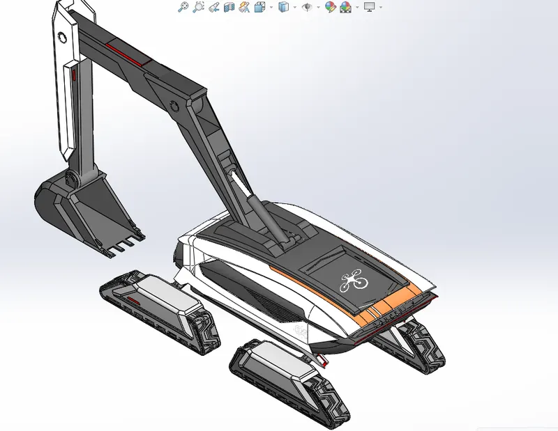
ISOMETRIC VIEW
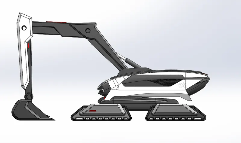
SIDE VIEW
RENDERING
It is the process of creating realistic images of the photorealistic model with the environment. It has been done in two ways in solid works. The following are the two ways.
- Photo view 360
- Solid works visualize
SOLID WORKS VISUALIZE
CONCLUSION:
- Learn to use many commands like Surface knit, Surface loft,Cut sweep etc...
- Assembled excavater by understanding Concentric mate, Coincident mate, Distance mate, Angle mate and Parallel mate.