Photo Realistic Rendering
PHOTO REALISTIC RENDERING
OBJECTIVE:
The primary aim of this project is to acquire comprehensive proficiency in SOLIDWORKS part modeling, SOLIDWORKS assembly, and rendering. This will involve:
1) Meticulously modeling each component of the American chopper with precise dimensions and visual attributes utilizing SOLIDWORKS part modeling.
2) Systematically assembling all constituent parts of the American chopper employing SOLIDWORKS assembly.
3) Generating a highly realistic rendering of an American chopper using SOLIDWORKS PhotoView.
INTRODUCTION:
SOLIDWORKS is a robust solid modeling software utilized for computer-aided design (CAD) and computer-aided engineering (CAE) and is extensively employed in the manufacturing sector. This project aims to provide a comprehensive understanding of SolidWorks by focusing on the modeling and photorealistic rendering of an American Chopper.
The initial phase involves the precise sketching and modeling of each component of the American Chopper. Following the creation of all individual parts, the next step is to assemble them using the SolidWorks assembly features. The model will then be enhanced through the application of suitable decals, the establishment of scenes and environments, and the incorporation of cameras and lighting. Ultimately, realistic images will be rendered utilizing SOLIDWORKS add-ins, specifically SOLIDWORKS PhotoView 360 and SOLIDWORKS Visualize.
1. AMERICAN CHOPPER DESIGN PROCEDURE:
- Design and creation of components/parts,
- Assembly of designed components/parts,
- Application of decals, camera setup, and scene configuration,
- Rendering.
DESIGN APPROACH:
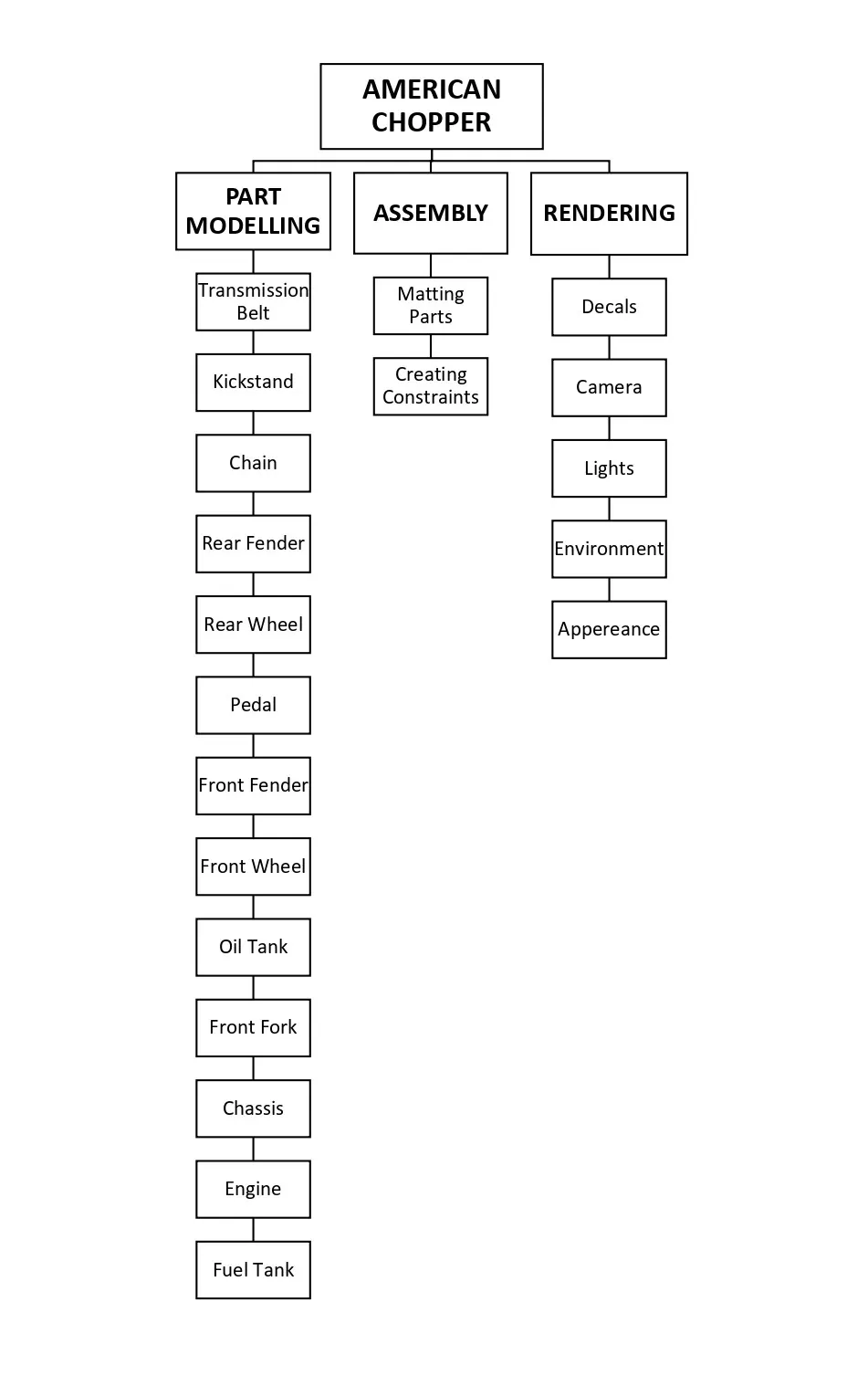
TERMINOLOGY
The following terms are consistently used throughout the SOLIDWORKS software and its documentation.
Origin – The model's origin is represented by two blue arrows, indicating the (0, 0, 0) coordinate of the model. When a sketch is active, the sketch's origin is denoted in red, also representing the (0, 0, 0) coordinate specific to the sketch. It is important to note that dimensions and relations can be applied to the model's origin, whereas they cannot be assigned to the sketch's origin.
Plane – Flat construction geometry enables the utilization of planes for various purposes, including the creation of two-dimensional sketches, the provision of selection views of models, and the establishment of neutral planes within draft features.
Axis – Straight line used to create model geometry, features, or patterns. Axis can be created in different ways, including intersecting two planes. The SOLIDWORKS application creates temporary axes implicitly for every conical or cylindrical face in a model.
Vertex – Point at which two or more lines or edges intersect.
Edge – Location where two or more faces intersect and are joined together. Edges can be selected for sketching and dimensioning.
Face – Boundaries that help define the shape of a model or a surface. A face is a selectable area of a model or surface.
TYPES OF COMMANDS AND THEIR EXPLANATIONS
Sketch – Please retain the following directive: "Generate the sketch, establish the appropriate dimensions, and determine the placement of relations.".
Features – The selection of suitable features, such as extrudes and fillets, necessitates a deliberate determination of the most appropriate features to apply and the optimal sequence in which to use them.
Surface – A surface is a geometric entity that is utilized in the creation of solid features.
Assembly – Please ensure to select the components for mating and specify the types of mates to be applied.
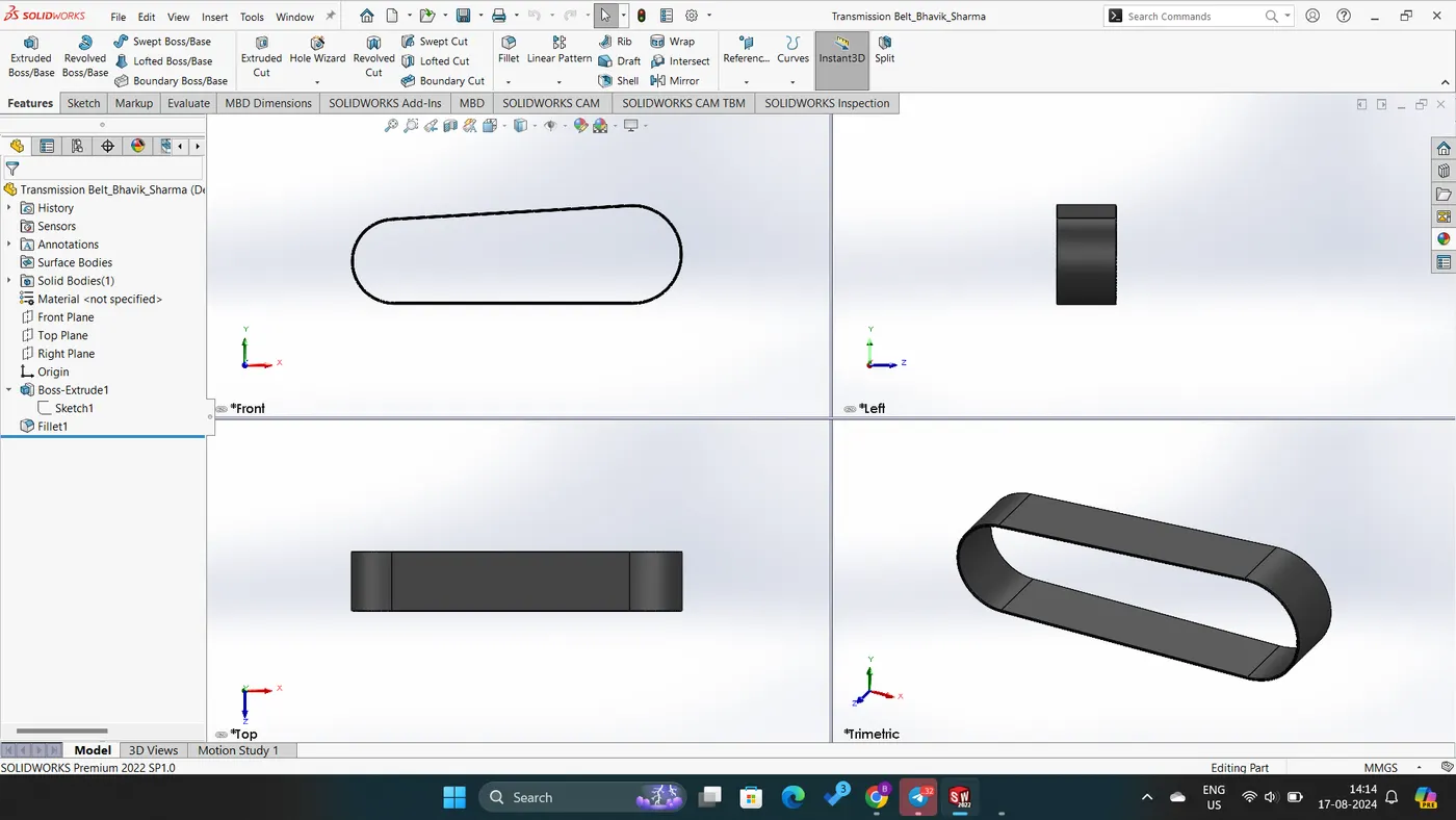
A. Transmission Belt
Procedure:-
- To begin, open a new part file and set the unit system to metric from the bottom right-hand corner.
- The front plane serves as the basis for creating the sketch of the transmission belt.
- Utilize the line command to draw a horizontal line from the origin to the right, followed by a continuous arc tangent to the line.
- Subsequently, draw another horizontal line from the end of the first arc towards the left, and connect both horizontal lines with an arc.
- Ensure that the connecting points of the arcs are tangent to the horizontal lines.
- Establish the starting point as coincident with the origin and apply the necessary dimensions using the smart dimensions tool to fully define the sketch.
- Once the sketch is fully defined, offset it outward to create the desired thickness for the transmission belt.
- Proceed to extrude the sketch from the sketch plane using the blind option, and add the required fillets along the edges of the belt on both sides.
- Finally, save the part while applying the matte rubber appearance.
B. Kickstand
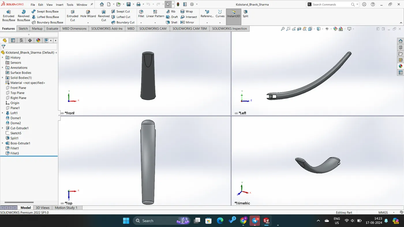
Procedure:-
- To begin the design process, initiate a new part file and select the metric unit from the bottom right-side corner.
- Next, sketch an ellipse on the front plane and ensure its center point is coincident with the origin.
- Subsequently, create a spline originating from the origin on the midplane, and apply the necessary dimensions.
- Generate a new plane perpendicular to the spline using the plane tool from reference geometry.
- Utilize the reference plane to sketch another ellipse, ensuring its center point intersects with the endpoint of the spline.
- Subsequently, create a loft between the two ellipses using the Lofted Boss/Base tool. Align the loft with the spline using centerline parameters.
- Construct two domes on either side of the lofted model using the Dome feature, adhering to the required dimensions.
- Subsequently, perform a rectangular extruded cut on the midplane's bottom right side using the Extruded Cut with Through All-Both option to create a clamping socket.
- Extrude a circular holder between the clamping socket by sketching a circle on the top plane.
- Utilize the split tool to remove a small portion of the part from the lower side of the kickstand to achieve the desired ground clearance.
- Complete the part by adding fillets to the required edges and applying the chrome plate appearance. Finally, save the part to preserve the design.
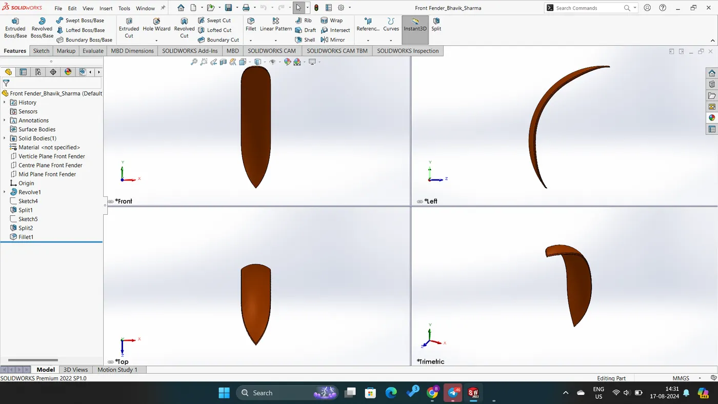
C. Front Fender
Procedure:-
- Begin by creating a new part file and setting the metric unit from the bottom right-hand corner.
- On the front plane, sketch a 3-point arc using the smart Dimensions tool to achieve the required dimensions.
- Subsequently, use the Offset Entities tool to inwardly offset the arc and connect the two arcs by sketching a line on both sides.
- Add the necessary sketch relations for creating revolves using Revolved Boss/Base.
- Utilize the split option to remove the unwanted portion from both ends and then apply fillets around the edges to achieve a smooth edge for the fender.
- Finally, save the part by adding an appropriate appearance.
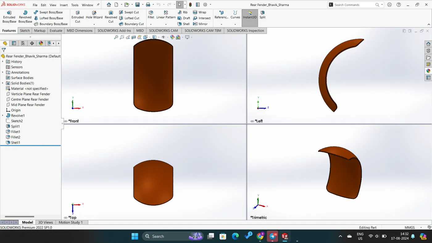
D. Rear Fender
Procedure:-
- In the process of creating a new part file, it is imperative to establish and adhere to metric units, which can be set from the bottom right-hand corner.
- A 3-point arc should be sketched on the front plane with specific dimensions using the smart Dimensions tool.
- Subsequently, the arc should be inwardly offset using the Offset Entities tool, and two arcs should be joined by sketching a line on both sides.
- A horizontal construction line should be drawn from the origin, and the necessary sketch relations should be added to create a revolve using Revolved Boss/Base.
- To achieve a smooth edge for the fender, a curve must be drawn using a spline on the top plane, and the portion not required should be split.
- Following this, a shall should be created on the inside face of the fender, and fillets should be added throughout the edges.
- Finally, the part should be saved after applying an appropriate appearance.
E. Chain
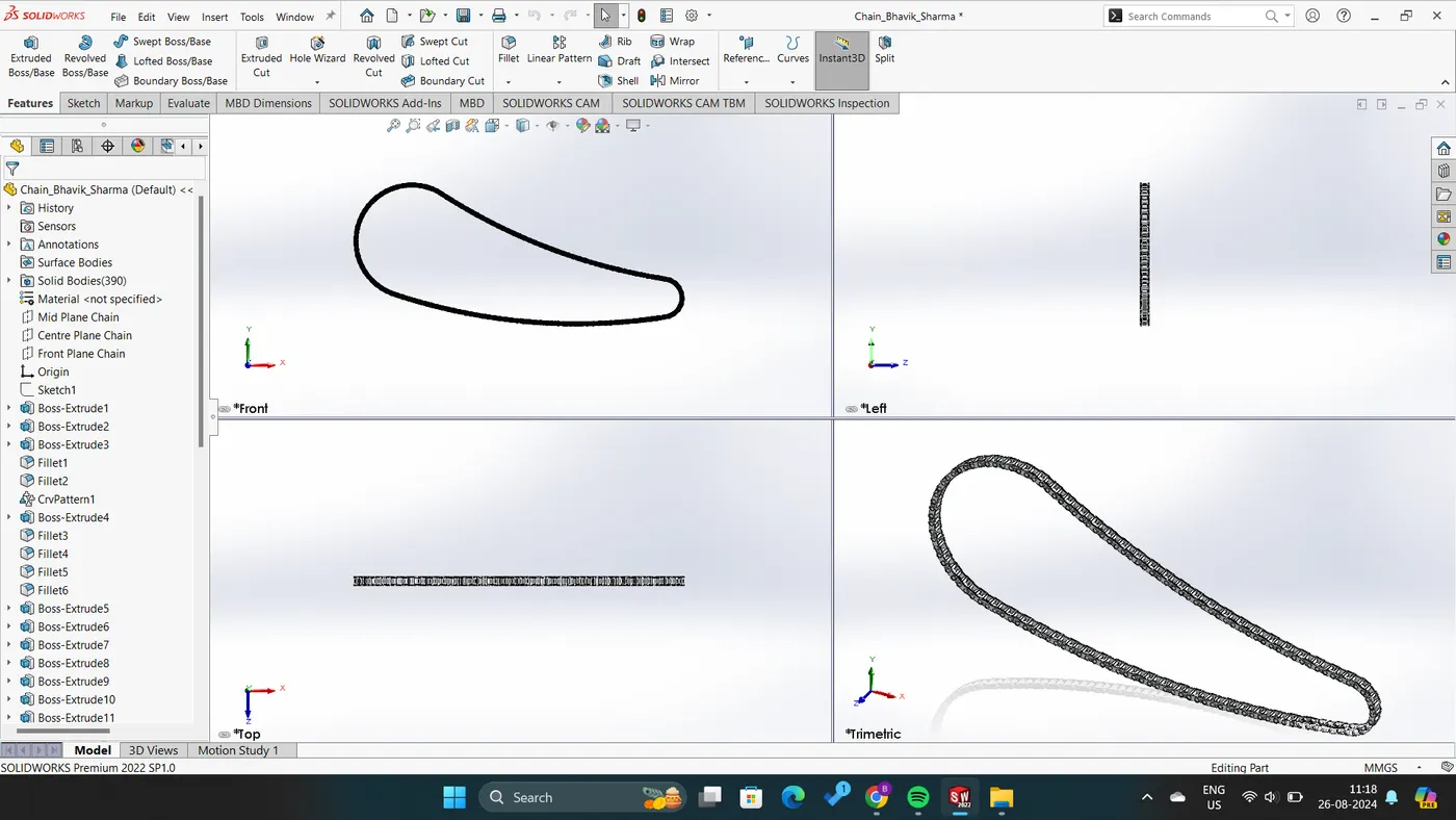
Procedure:-
- To initiate the process, please create a new part file and set the measurement unit to metric from the options located in the bottom right corner. Subsequently, select the front plane, referred to as the Midplane chain, to define a chain path utilizing the Construction Line and Arc commands.
- Following this, proceed to sketch both the outer and inner chain links on the front plane by employing the Circle, Line, and Arc commands. Upon completion of the sketches, save them as a block for future reference.
- Next, utilize the Insert Block command from the Tools menu to incorporate the chain links into the design. Extrude the pins and blocks separately according to specified requirements through the Extruded Boss/Base feature.
- Furthermore, apply the Curve Driven Pattern to replicate the chain links and pins along the designated path as per your needs. To achieve symmetry, employ the Mirror command to replicate the chain links using the front plane (Midplane chain) as the reference.
- Finally, ensure to save the part file, incorporating the requisite fillets and applying a chrome appearance as necessary.
F. Pedal
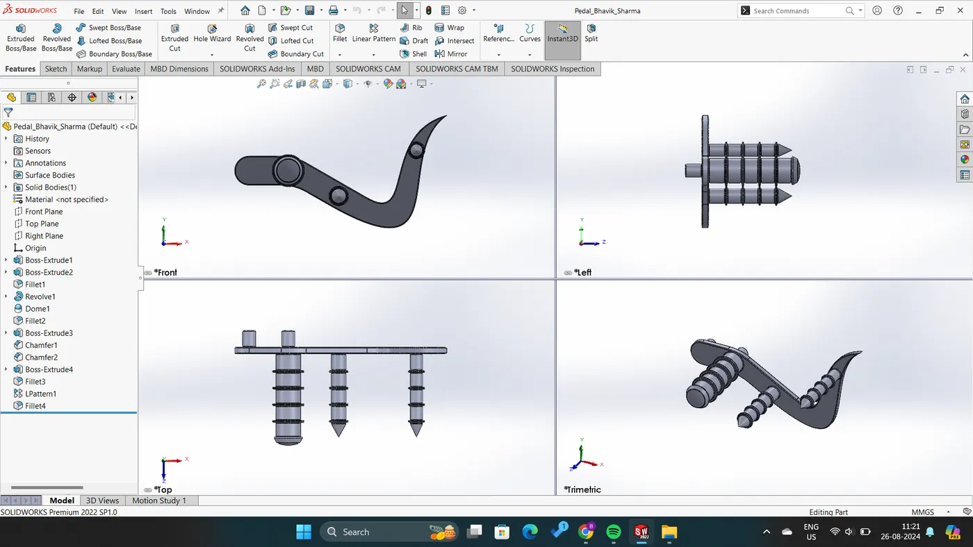
Procedure:-
- To initiate the process, create a new part file and establish metric units from the settings located in the bottom right corner.
- A sketch of the pedal has been developed on the front plane and thoroughly dimensioned utilizing lines, arcs, and splines.
- The footrest was subsequently extruded from this single sketch employing the Extruded Boss/Base feature, with suitable fillets applied as required.
- Following this, a sketch was created on the top plane utilizing construction lines and normal lines, allowing the sketch to revolve around the construction line.
- A dome was formed on the face of the footrest as part of this design process.
- Furthermore, circular extrusions were generated by utilizing the offset, fillet, chamfer, and linear pattern options.
- In conclusion, the part was saved with a chrome appearance applied to enhance its visual quality.
G. Oil Tank
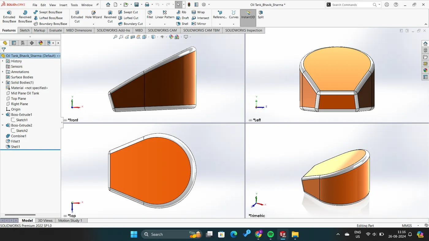
Procedure:-
- Begin by creating a new part file and configuring the metric unit settings located in the bottom right corner.
- Select the top plane for the initial sketch, utilizing construction lines, midpoint lines, and arcs to develop the desired geometry. Subsequently, extrude this sketch.
- Proceed to sketch on the front plane by drawing a spline and a line, ensuring that all dimensions are set to achieve a fully defined state.
- Extrude this sketch using the midplane option and the "through all" function to merge the two separate bodies.
- Conclude by saving the part, incorporating suitable fillets along the edges, and applying an appropriate appearance to enhance its visual presentation.
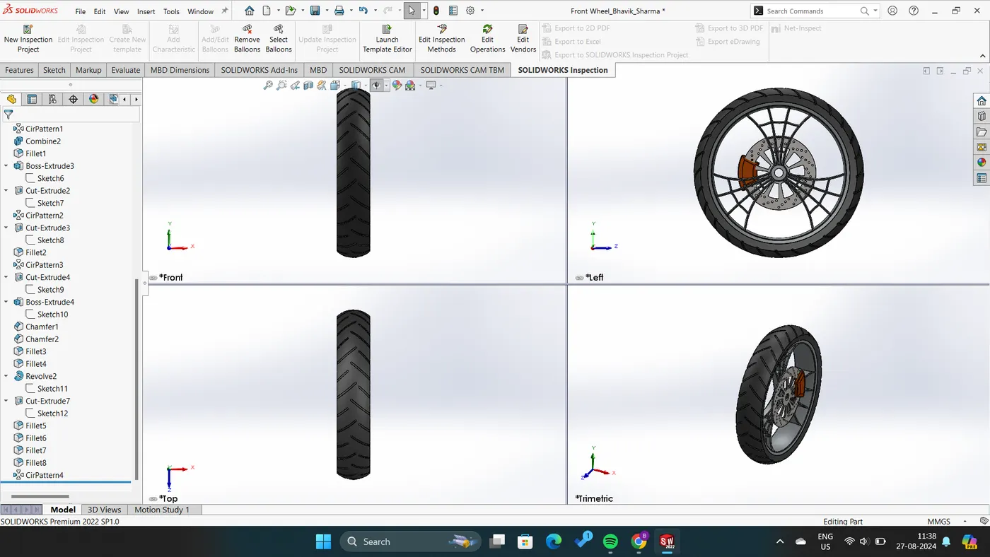
H. Front Wheel
Procedure:-
- To initiate the design process, create a new part file and set the metric unit of measurement from the lower right-hand corner.
- Begin by selecting the Front Plane to sketch the outer profile of the wheel, ensuring that all dimensions are applied to achieve a fully defined sketch. Proceed to revolve the sketch around the temporary axis.
- Next, sketch on the Right Plane by drawing a vertical construction line originating from the origin, followed by an additional line at an angle.
- Incorporate a spline and then mirror all three entities across the vertical construction line. Extrude the resulting geometry.
- For the spider-webbed design, offset all three drawn entities and utilize the cut-extrude feature to remove any undesired portions.
- Connect the spokes using 3-point arcs, make offsets, and complete the sketch with lines to ensure it is closed. Subsequently, extrude this sketch.
- Select the Front Plane once more to draw a spline, utilizing a revolved cut to eliminate unnecessary areas.
- Apply a circular pattern to the spokes and combine them to form a single solid body.
- For the rotor component, sketch on the Front Plane by creating a circle and extruding it. Implement a circular pattern to produce holes across the rotor, followed by the removal of extraneous material.
- Regarding the caliper, sketch a circle and line to reflect the design of the body. Utilize the trimming feature to eliminate unwanted areas and perform an extrusion. Apply chamfering and filleting as necessary.
- Finally, for the tire, use the rim as a means to convert entities and revolve. Create rectangles, applying appropriate dimensions and relations to achieve a fully defined shape. Execute an extruded cut and apply fillets to complete the design.
I. Front Fork
Procedure:-
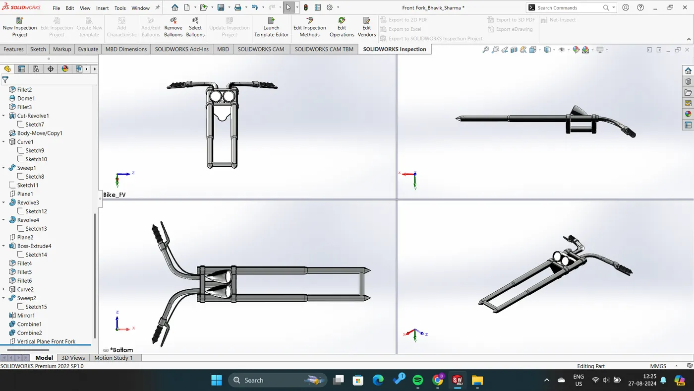
- To begin, create a new part file and configure or establish a metric unit of measurement in the bottom right corner of the interface.
- For the fork tube, initiate a sketch on the front plane by drawing a cylindrical representation using line segments.
- Ensure that the sketch is fully defined by applying appropriate dimensions and relations, and subsequently perform a revolve operation.
- Regarding the triple clamps, select the top plane to sketch a concentric circle that corresponds to the fork tube.
- Additionally, create another circle positioned to the left and upward of the first. Utilize connecting lines between the circles and ensure the sketch is fully defined by applying the required dimensions before proceeding to extrude the feature.
- For the bulb, select the front plane and draw a horizontal construction line followed by a spline. Execute a revolve operation on this sketch. Move the bulb in the Z direction and apply a fillet to refine its edges.
- To model the handle and brake wires, select the top plane and use a spline to define the shape of the handle, ensuring that it is fully defined. At the terminus of the spline, draw a circle and employ the sweep feature to follow the intended path.
- After modeling the various components, select the bodies, mirror them as necessary, and combine them into a single assembly. Finally, apply an appropriate appearance to the fork component to enhance its realism.
J. Rear Wheel
Procedure:-
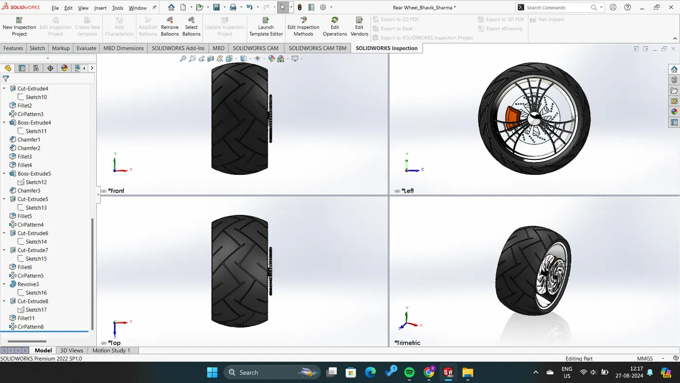
- To initiate the design process, create a new part file and select a metric unit from the bottom right corner of the interface.
- Proceed to sketch the outer contour of the wheel on the Front Plane and apply sufficient dimensions to achieve a fully defined sketch. Subsequently, revolve the sketch around the designated temporary axis.
- Next, transition to the Right Plane to establish a vertical construction line originating from the origin, along with an additional line drawn at an angle.
- Utilize a spline to complete the shape, and then mirror all three entities across a vertical construction line before extruding the resultant shape.
- For the spider-webbed design, offset the three drawn entities as necessary and eliminate the superfluous portions using the cut extrude feature.
- Subsequently, connect the spokes with 3-point arcs, apply an offset, and complete the sketch by utilizing straight lines. Extrude the finalized sketch.
- Return to the Front Plane to sketch the rotor by drawing a circle and extruding it. Employ a circular pattern to create uniformly spaced holes over the rotor and remove any undesired sections.
- For the sprocket, begin by drawing a circle and extruding it accordingly. Apply a chamfer to the outer edge and implement the creation of teeth through cut extrusion. Remove any excess material with a cut extrude operation and apply a fillet to refine the design.
- For the caliper, sketch a circle and line following the intended body design. Trim any extraneous areas and extrude the shape. Apply chamfers and fillets to enhance the product's aesthetics and functionality.
- Lastly, for the tire, utilize the rim as converted entities to initiate a revolution. Draw rectangles and apply the necessary dimensions and relations to ensure a fully defined sketch. Execute a cut extrude operation and apply fillets as required.
K. Chassis
Procedure:-
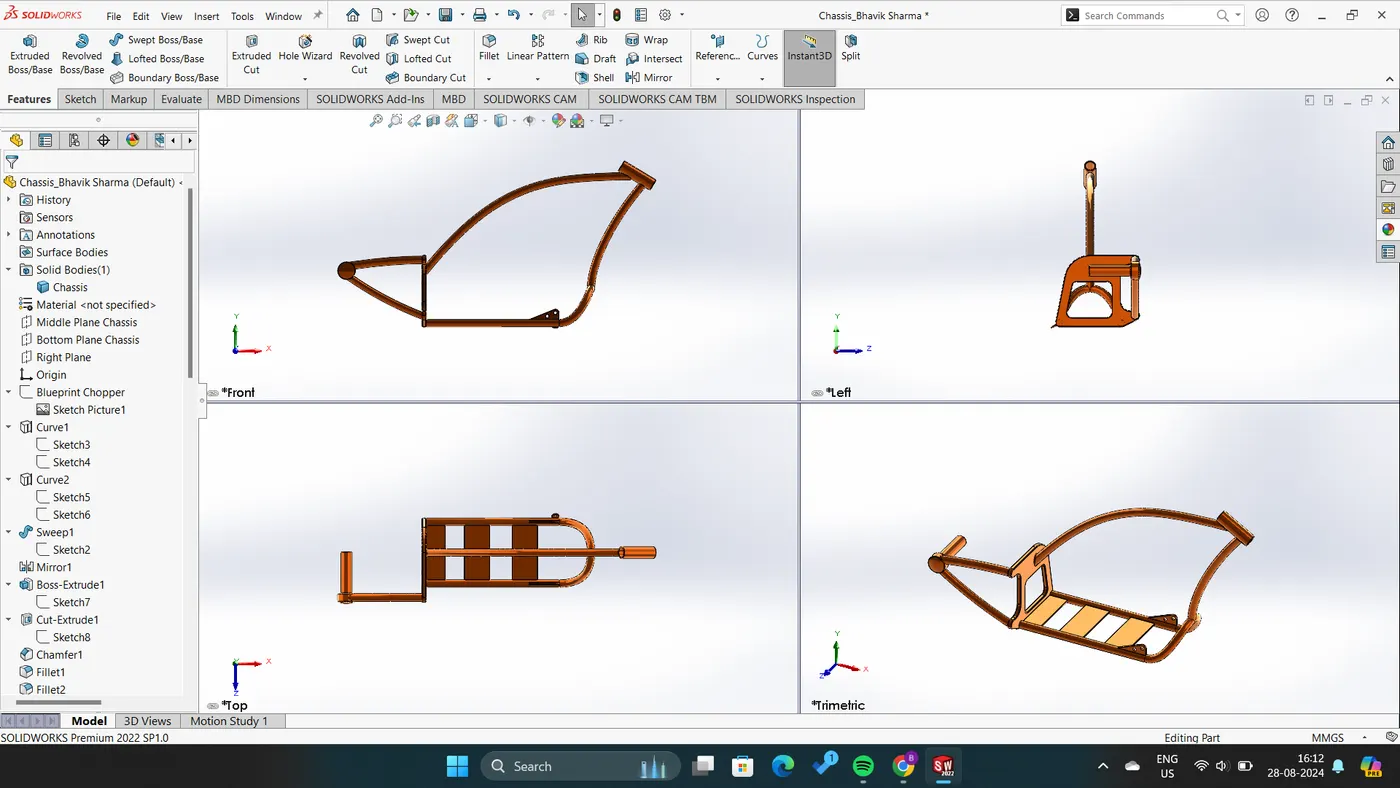
- To initiate the design process, a new part file was created, and metric units were set from the bottom right corner of the interface.
- Subsequently, the blueprint was incorporated by utilizing the 'Insert Sketch Pictures' option on the mid-plane, which facilitated the development of the sketch for the Frame.
- The Bottom Rails for the engine placement were generated by drawing a projected curve, which was then swept using the Swept Boss/Base feature; the opposite half of the component was created through mirroring.
- The Back Frame was developed employing Extrude Boss/Base and Revolved Cut techniques. Thereafter, the necessary chamfers and fillets were applied to enhance the design.
- The Bottom Tail tube was constructed using both the Swept Boss/Base and Extruded Boss/Base features, while the dome on the front face of the hub was achieved through the application of the dome option.
- For the design of the steer tube, the Extruded Boss/Base and Extruded Cut methods were utilized effectively.
- The foot pedal mounts were fabricated using Extrude Boss/Base, Extrude Cut, Mirror, and Fillet functionalities. Additionally, Split and Combine options were employed to effectively group the various components of the Frame.
- In conclusion, the part was saved with a chrome appearance to meet aesthetic requirements.
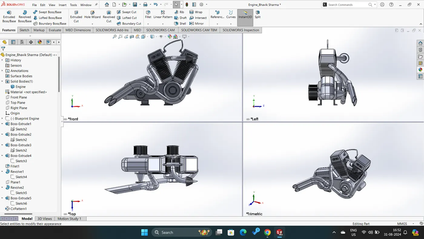
L. Engine
Procedure:-
- To initiate the process, a new part file should be created, ensuring that the metric unit is set from the lower right-hand corner of the interface.
- The blueprint is subsequently incorporated by utilizing the "Insert Sketch Pictures" option on the mid-plane. Following this, the required sketch is meticulously drawn based on the blueprint and extruded using the Extruded Boss/Base feature, with appropriate fillets applied as necessary.
- A reference plane is then established through the Reference Geometry tool to facilitate the development of the transmission system.
- This system is constructed employing the Revolved Boss/Base, Extruded Boss/Base, Extruded Cut, Chamfer, and Circular Pattern features. Fillets and dome features are applied to the designated areas to enhance design integrity.
- For the creation of the engine cylinders, the Extruded Boss/Base feature is utilized, accompanied by the application of a dome feature on each end of the cylinders.
- The cooling fins are produced using the Linear Pattern, while the opposing half is mirrored to correspond with the fins and domes.
- The Air Inlet ducts are crafted employing Circular Patterns, Extruded Cut, and Revolved Boss/Base techniques. In designing the exhaust pipes, the Composite Curve feature is applied on the reference plane created on the face of the engine cylinder.
- Subsequently, the Swept Boss/Base feature is used to form the exhaust pipes, with the Split feature employed to remove any unwanted portions.
- The spark plugs are manufactured utilizing both the Extruded Boss/Base and Swept Boss/Base features. In conclusion, the part is saved, incorporating appropriate appearances to finalize the design.
M. Fuel Tank / Gas Tank
Procedure:-
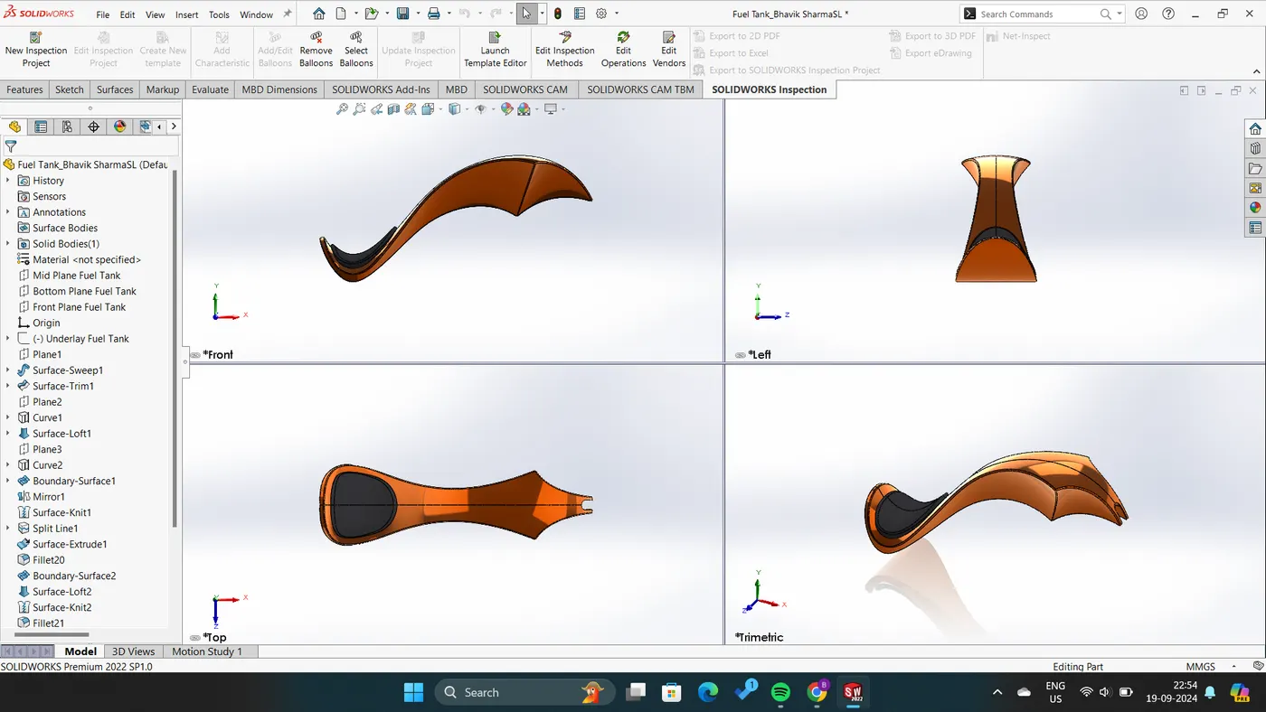
- A new part file was created, with metric units configured from the bottom right corner of the interface.
- Subsequently, a plane was established about the front plane, followed by the creation of a sketch that was swept into form utilizing the Swept Surface feature. The surface trim tool was employed to achieve the desired shape of the fuel tank.
- In the next phase, an additional plane was created to facilitate a projected curve, which was subsequently used to generate a surface loft with the Lofted Surface tool.
- Another plane was introduced, and a further curve was projected, allowing for the development of the fuel tank surface through the Boundary Surface tool.
- One half of the design was mirrored, and both halves were joined at an edge using the Knit Surface tool.
- The Split Line feature was then utilized to generate the sketch for the seat, and the Surface Extrude option was implemented to create the solid body of the seat.
- Appropriate fillets were added to ensure smooth edges.
- To position the fuel tank atop the frame's top tube, a tube-shaped portion was removed utilizing a combination of Boundary Surface, Lofted Surface, Knit Surface, and Swept Cut tools. After applying the appropriate appearance settings, the part was saved accordingly.
2. Assembly of American Chopper:
Assembly serves as a prominent feature of SOLIDWORKS, enabling users to compile individual components through the application of assembly mates. Assembly mates establish geometric relationships, including coincident, concentric, and parallel, between different parts during the assembly process. Within SOLIDWORKS, three primary types of mates are utilized to facilitate this assembly.
- Standard mate – They are the common geometric relations such as coincident, concentric, parallel, etc.
- Advanced mate – This option allows us to decide the distance between the components, the angle between the components, the width option, etc.
- Mechanical mate – Mechanical mates for components such as Cams, Gears, and Universal joints. Deal with real-world interaction of the elements.
Procedure
- To initiate the assembly process in SolidWorks, please create a new assembly document and confirm that the appropriate unit settings are applied.
- Utilize the "Insert Component" function to add the chassis as the first component without selecting any additional options.
- The chassis should automatically mate with the assembly planes; it is essential to ensure that the planes of both the assembly and the chassis are aligned.
- Subsequently, insert all remaining components and apply proper mating to each part in relation to the chassis.
- This will ensure that as the chassis is moved, all components will move in conjunction with it.
- It is vital to apply the correct mates, dimensions, and relationships to facilitate the floating of the chassis, allowing it to be repositioned to verify that all components are properly synchronized with the chassis.
- The front wheel should be mated with the front fork to ensure that as the fork rotates, the wheel also rotates accordingly.
- Additionally, please confirm that both the wheels and the stand are positioned to make contact with the ground level, and apply the appropriate mate to connect with the chassis's top plane.
- Once all components have been inserted and the necessary mates have been applied, please save the assembled document accordingly.
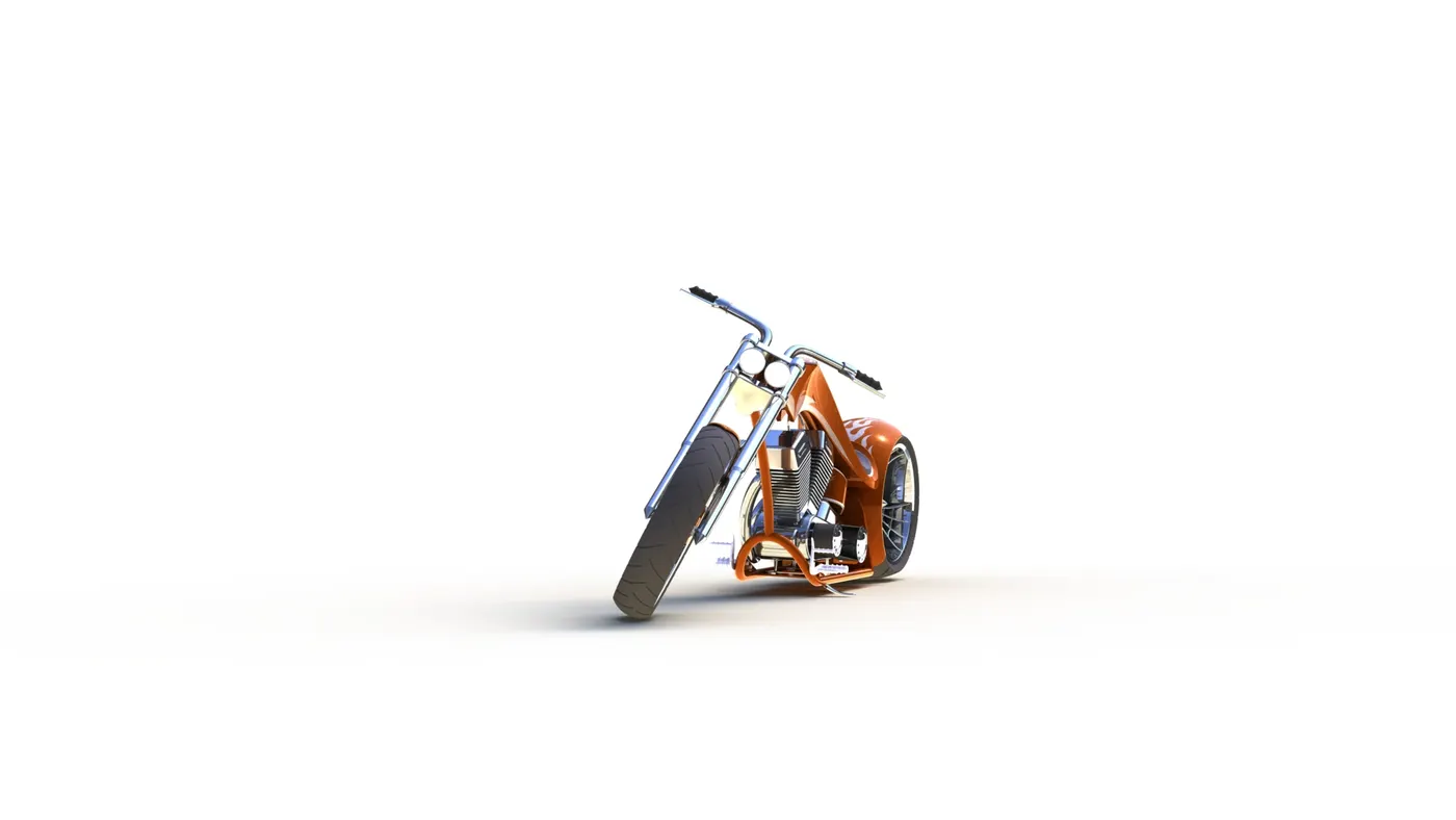
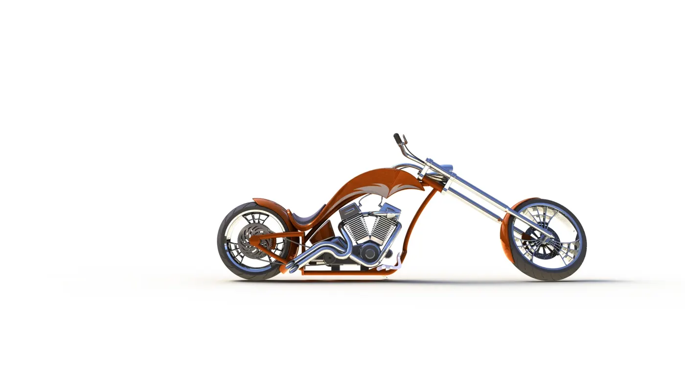
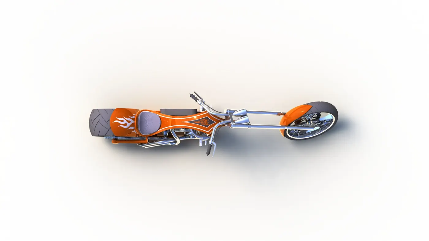
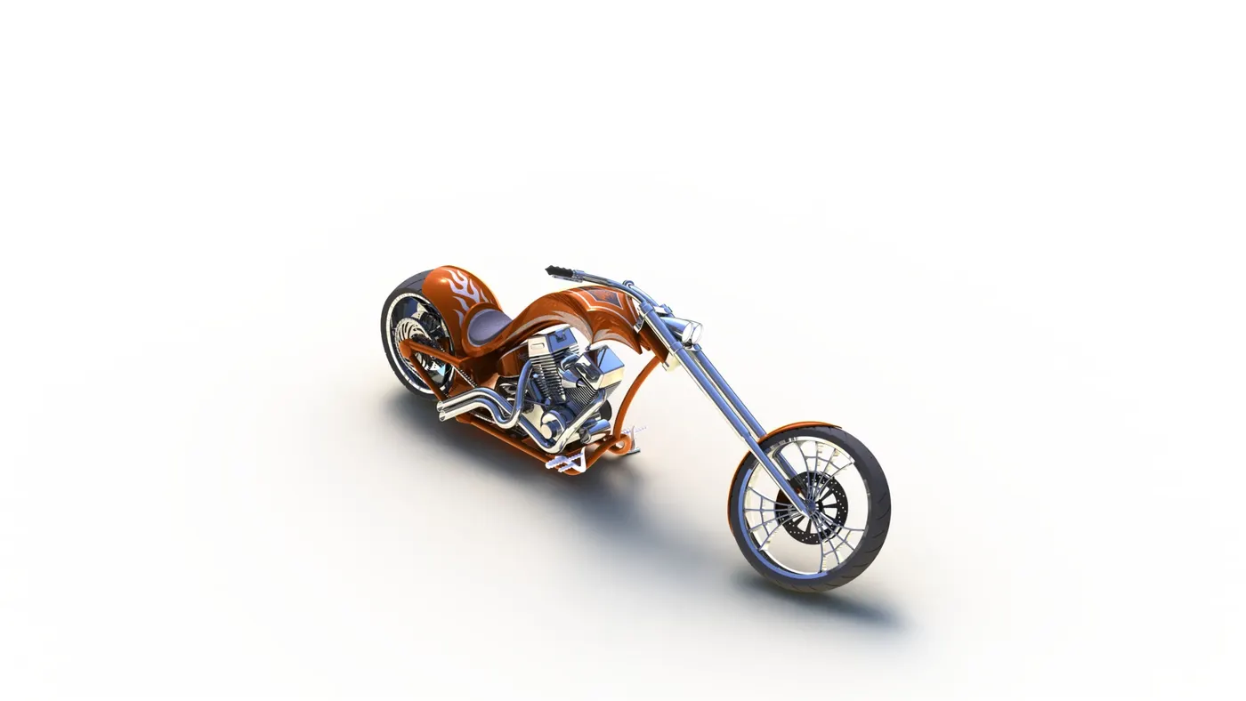
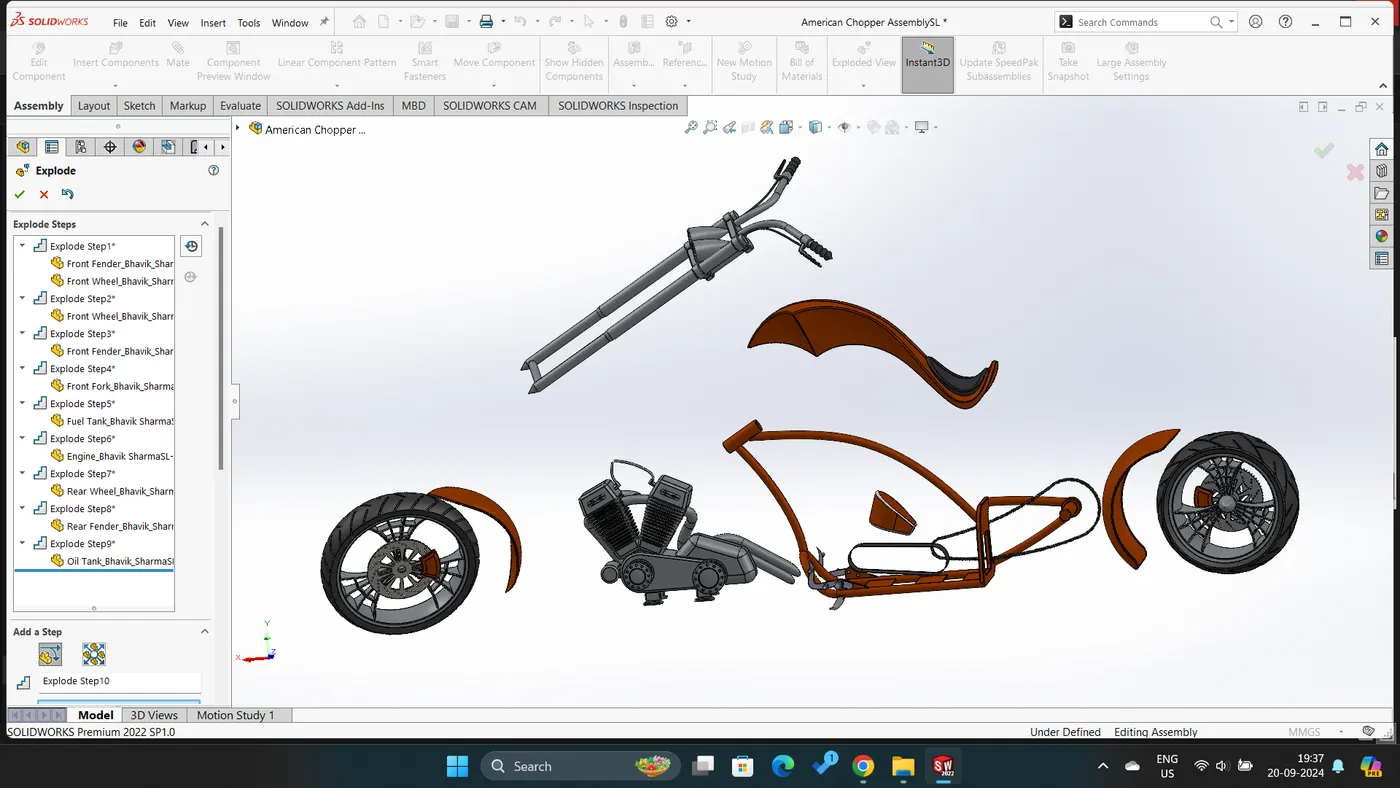
The different views of the assembled chopper are given below:-
1) Front View
2) Right side View
3) Top View
4) Isometric View
5) Exploded View
3. Rendering of American Chopper
Rendering is the process of creating a Hyper realistic image of the components/Assembly. Here we are using SOLIDWORK add-ins as SOLIDWORK Photo View 360 and SOLIDWORK Visualize to render our assembly.
- PhotoView360 – PhotoView 360 produces photo-realistic renderings of SOLIDWORKS models. The rendered image incorporates the appearances, lighting, scenes, and decals included with the model.
- Solidworks Visualize – SOLIDWORKS Visualize allows us to leverage our 3D CAD data to create photo-quality content in the fastest and easiest way we can from images to animations, interactive web content, and immersive Virtual Reality. SOLIDWORKS Visualize is the Camera for our CAD data.
Before the final render, we have options such as adding.
- Decals – Decals are the graphics that we can wrap on a solid body. For example Adding stickers to the fuel tank, oil tank, etc.
- Camera – Using the camera option we can set up a camera view and save that view.
- Scene – The option to set up a scene, Environment, and background.
- Lights – Using the light option we can add lights to the model. Types of lights in SOLIDWORKS are Directional light, Point light, Spotlight, and sunlight.
Procedure for PhotoView 360
For each Solidworks model to be rendered, the process required the same steps. Most of the steps are done within Solidworks with only a few steps requiring Photoview 360.
The following steps are required until a satisfactory output is obtained:-
- Position the Model – Use a standard view, or use zoom, rotate, and move to position the model in the desired position.
- Apply appearance to the model, feature, and/or selected faces.
- Set the Scene – Select one of the various present scenes, or set your own background and scenery.
- Set Lighting- Adjust the environmental lighting or add direct lights. Preview Render The preview is a test of the settings before the final render.
- Render the Model – The model is rendered to the final render window.
- Save Output – To be used, the final render must be saved as a separate image file.
- Post Processing – The rendered image output is not always the final product. Often the image output is used with other programs for additional effects.
Procedure for Creating Visualization
- Create a new project by importing the required assembly or models into the Solidworks Visualize.
- Add the required appearance, environments, backplates, and lights.
- By using the camera tool position the designed model in a realistic view.
- Make sure that the model touches the floor. It can be achieved by using the snap-the-floor option on models.
- By applying the required setting the required output can be rendered using the output tool.
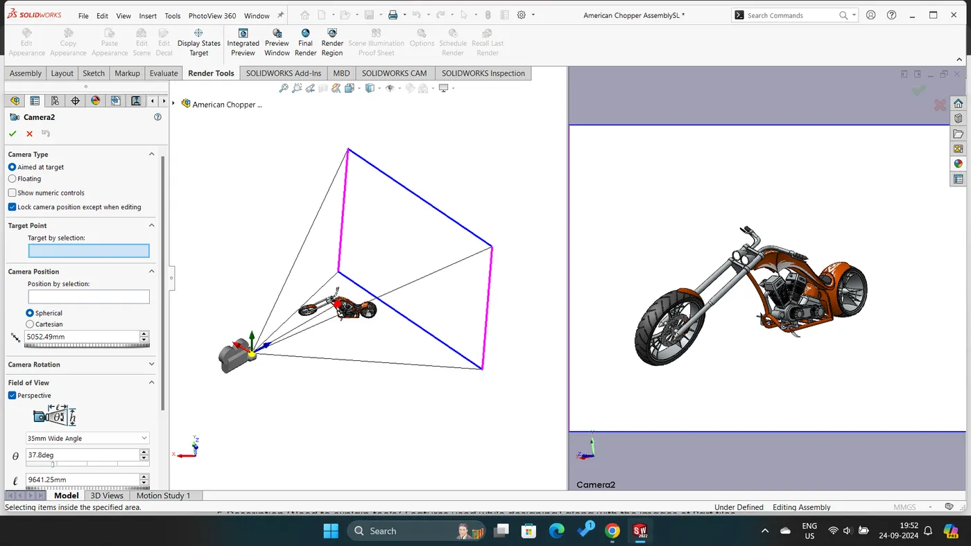
Fig: Camera Positioning
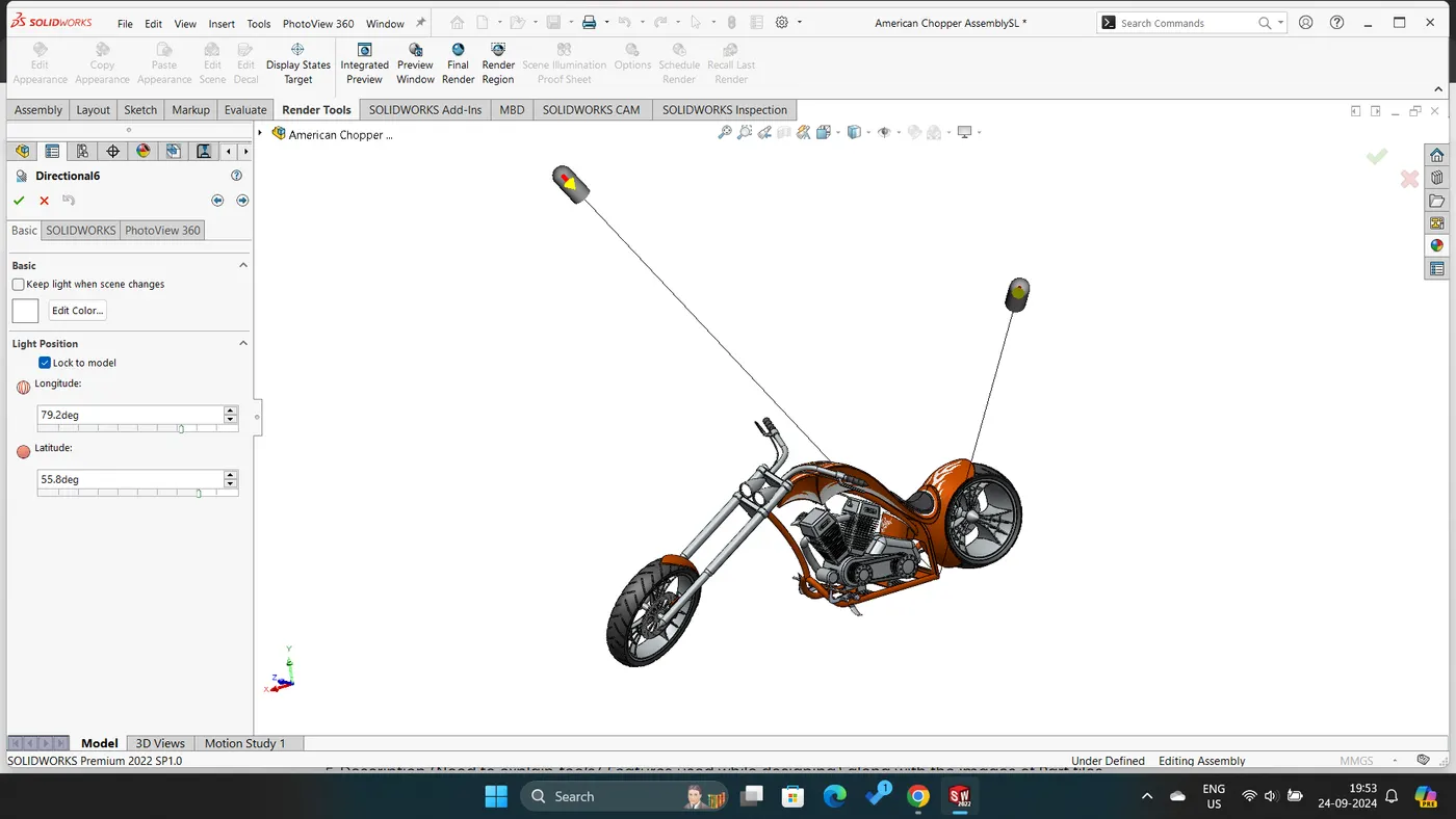
Fig: Lights Positioning
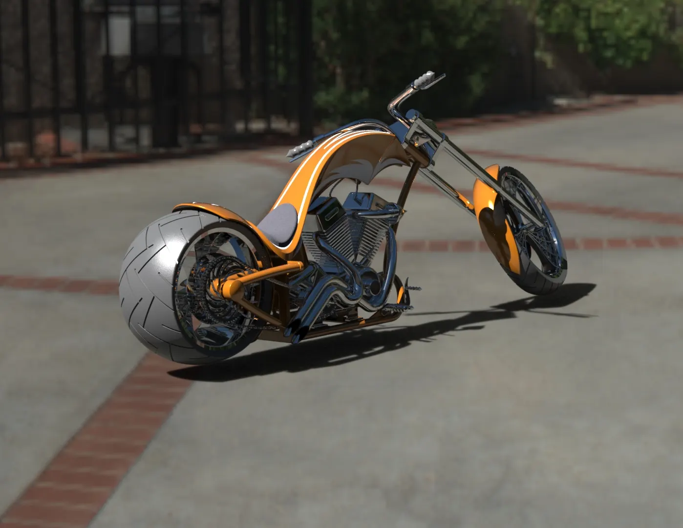
Fig: Environment Rendering
Conclusion
- All components have been created with precise dimensional and geometric constraints, resulting in an enhanced understanding of part modeling.
- The assembly of the American chopper has been completed, during which I have become proficient in utilizing nearly all tools and features available in SolidWorks assembly.
- Furthermore, I have produced hyper-realistic images and acquired extensive knowledge in employing SolidWorks PhotoView 360 and SolidWorks Visualize.
Note: As the file size is quite big I have attached file link below.