Photo Realistic Rendering
MODELING OF AMERICAN CHOPPER ON SOLIDWORKS
INTRODUCTION
In this project, we are using SOLIDWORKS software to learn about the design of the American chopper assembly. In this, we first learn to set a templet of over own(dimensions, add-ins) , use the commands, and then we start drawing sketches in the parts module. After designing all the parts, we do the assembly with the help of an assembly module. If we don’t have dimensions to sketch then we use a blueprint sketch here we import the sketch picture and draw the sketch accordingly. After assembly, we add decals, lights, camera and do a rendering of the chopper by using SOLIDWORK visualization.
The components which we designed for American chopper Bike are:-
- Chassis.
- Engine with exhaust
- Front wheel and rear wheel.
- Front Fork.
- Front and rear
- Oil tank.
- Gas tank.
- Chain.
- Transmission belt.
- Kickstand .
- Foot pedal/Pedal stand.
OBJECTIVE:
- To learn the basic commands of
- With the help of blueprint sketch we design all the parts of
- Assembling all the parts in
- Get the knowledge on basic concepts like decals, light and camera for photo-view 360.
- Getting realistic view with the help of photo-view
- Rendering of American chopper Bike has done with help of solidworks visualization
Design Approach Flow Chart:
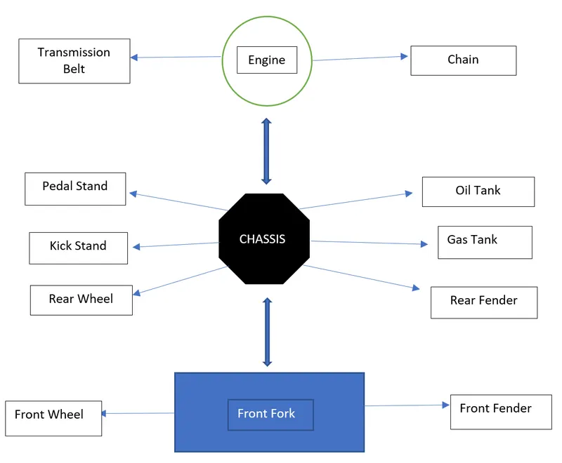
FEATURES WE USE IN DESIGN:
Let’s see what are the features and properties used in the entire model to design different parts:
- Extrude boss
- Fillet
- Revolve boss feature
- Extrude cut
- Shell
- Linear pattern
- Circular pattern.
- Mirror
- Reference geometry
- Projected curve
- Knit
- Mate
- Move
- Surface loft/Sweep surface/Boundary surface.
- Split
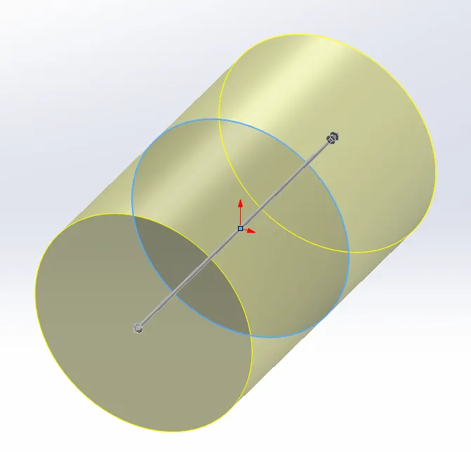
Extrude Boss This feature will be performed after 2D sketch is a closed figure and it is convert 2D sketch into a solid body. When we exit the fully defined sketch we get boss extrude option in the feature tab. It creates a complete solid body of closed entities with any size and shape. In this feature we can add dimensions to both the direction (direction 1 and direction 2) as per requirement. We can also use the default direction options it is blind, through all, up to next etc. the extrude can start from surface, midplane, from the vertex, etc. This is how we use this feature.
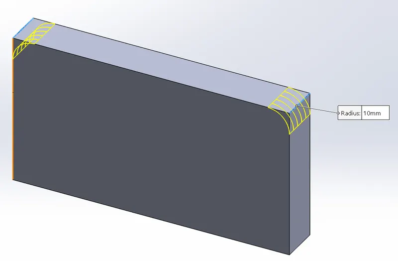
Fillet: This feature is used to make sharp edges machinable. To make those edges curve we add fillets. We can perform it in different sizes or radius. Various types of fillets end fillet, edge/total fillet.

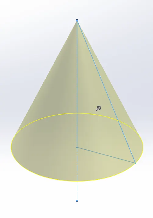
Revolve boss feature: This feature works on axis, by revolving the sketch around that axis. If there is no axis/reference line we can select an edge to ne reference of a sketch and it gives us appropriate geometry.
Extrude cut: As the name says when we want to remove material from solid part we draw sketch on the solid part and then we use extrude cut command it removes that part/surface from the original body.
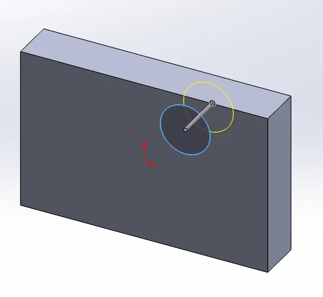
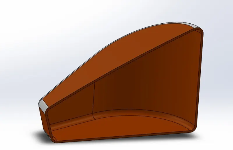
Shell:. It can convert solid objects to hollow in this tool we give inside thickness to the geometry and material will be removed from the body and it becomes hollow.
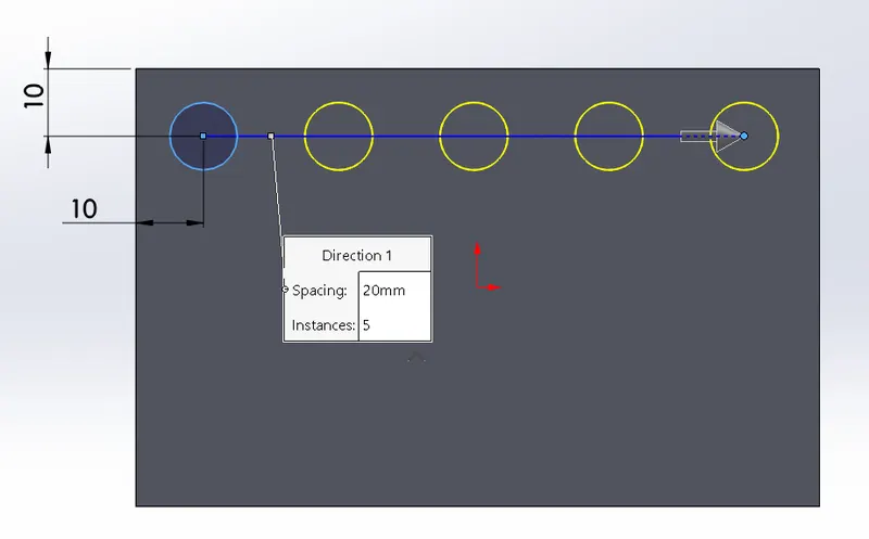
Linear pattern: Linear pattern is used to create single sketch/extrudes/extrude cut to use multiple times. In given angles/ path. This sketch/ extrudes are spaced uniformly.
Circular pattern: Circular pattern is used to create single sketch/extrudes/extrude cut to use multiple times. In given circular path. This sketch/ extrudes are spaced uniformly.
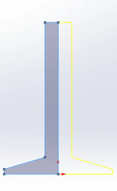
Mirror: This feature creates copy of sketches and solid part. When this feature is applied it need plane or axis as a reference to be mirrored. Select the body/sketch which is to be mirror, select an axis or plane then apply feature and the mirrored part will be automatically generated.
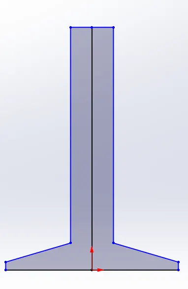
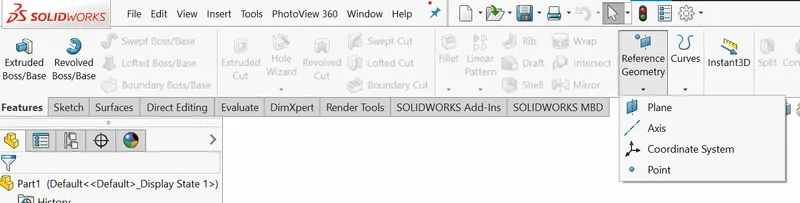
Reference geometry:. This can be used according to need in a sketch. If we want to create any new references in the sketch like axis, point and plane at any required angle.
Move: This feature helps us to move extrude parts above/below/left/right from the reference
Surface loft: This feature is used to convert 2D drawings to 3D surfaces. Here we can specify the direction of surface to be loft.
Split: This feature is used to remove the extra parts/ whatever part we like to remove. It is just like ‘TRIM’ command in 2D sketch.
Projected curve: The curve we create in two different 2D planes is projected in a 3Dspace. Generally, the curves are to be extruding surfaces. The curve extrusions will intersect and form a new curve in the space called intersecting curves.
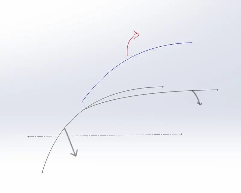
Knit: Use of knit surface tool to combine two or more faces and surfaces into one.
Mate: it is a command use to in assembly to join the two parts in any of these following relations.
The relations are:-
- Coincident mate: Coincident mate make two planar faces to become coplanar. This mate is use when two surfaces are inseparable.
- Concentric mate: This makes two circular faces/bodies to become concentric and can move along the same axis.
- Tangent mate: This feature can be use between two face /plane to make tangent relation between them.
- Angular mate: This make angular relation between the surfaces with some
- Mechanical mate
- Width mate: This option is available in in advanced mate option it is used when a body is located at the center in between two faces or edges it helps us to auto adjust the center alignment when the bodies dimensions has been changed.
- Screw mate
- Distance mate: this feature is used to fix or coincide a body at certain distance.
- Parallel mate: this feature is used when we want to make some edges, faces, planes parallel.
Components:
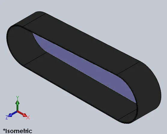
Transmission Belt: It is used to transmit the power with help of pulleys. Transmission belt is covered over the pulleys. The commonly used material for this is rubber.
Features used to create the transmission belt:
- Sketch
- Extrude
- Offset
- Fillet
- Appearance
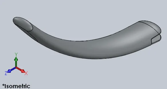
Kickstand: Open a new part fille by Click on new select part click ok. Go to sketch tab click on sketch select front plane and at origin draw an ellipse of the length of longitudinal axis is 40 mm and length of lateral axis 18 mm and set the relations that the longitudinal axis is horizontal and lateral axis is vertical and exit sketch and click on the right plane and slow select the right plane to rename it as midplane now click on midplane and select sketch and draw a single point spline as origin as the starting point and the endpoint in the second quadrant the horizontal distance of endpoint to origin is 110 mm and the vertical distance between them is 200 mm and exit the sketch and go to features and click on reference geometry and select plane now first select the spline and then select the endpoint to create the new plane. Now select the plane and click sketch and draw an ellipse of the length of longitudinal axis is 30 mm and length of lateral axis 12 mm and set the relations that the longitudinal axis is horizontal and lateral axis is vertical and exit sketch and go to features tab and click on lofted boss base and first select the smaller ellipse and then select the bigger ellipse and select the spline as the direction and over which of loft occur. Now create an elliptical dome on a bigger ellipse of size 13 mm and on a smaller ellipse of size 5 mm. Now select the plane and draw a midpoint horizontal line of length 50 mm and midpoint is related vertical to the origin, the midpoint is placed at 4.5 mm below the origin, exit the sketch and go to features and click on insert and then click on features and click on split and select the sketch and click on the cut part and then remove the unnecessary part and click ok. Now select midplane and click on sketch and select center point rectangle and draw as origin as center and dimensions 28 mm*8 mm and exit sketch and click on extrude cut and select the rectangle and select ‘through all both sides’ and click ok. Select the top plane and click on sketch and draw a circle at the origin of the bigger ellipse of diameter 9 mm and extrude it up to ‘next surface’ in both the directions and apply fillets of 2 mm and 0.5 mm to the edges. Click on appearance in the right corner of the window and go to materials select metal, click on chrome and click on chrome plate drag it and drop it on the extrusionThe kick stand in the part has higher curvature so we had edited our model in assembly and had tangential mate it to top plane in order to make it look real.
Features used to create the kickstand:
- Sketch
- Ellipse
- Splines
- Pierce
- Loft
- Cut extrude
- Boss extrude
- Split
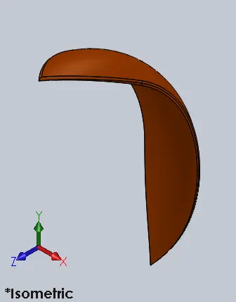
Front Fender: Open a new part fille by Click on new select part click ok. click on the front plane and slow select the right plane to rename it as vertical plane front fender. similarly, we rename the top plane and right plane as center plane front fender and midplane front fender. Go to sketch tab click on sketch and select vertical plane front fender draw a 3point arc of radius 125 mm above the origin, set the relations that both the endpoints are horizontal and the center of the arc is vertical relation to origin at a distance of 280 mm and offset it to a distance of 6 mm inward (towards origin) then draw vertical lines in the downward direction from the ends of the first arc, now click on extend entities and select the second arc so that it intersects the vertical line at both ends and trim the extra lines. Now draw a horizontal construction line passing through the origin of length 200 mm. now exit the sketch and go to features and click on revolved boss base and select construction line as center axis and the degree of revolution in direction_1 is 5 degree and in direction_2 is 130 degrees. Now select center plane front fender plane and go to sketch and draw a construction line passing through the origin and the length of 34 mm above the origin of fender now click on tools and select sketch tools and click on dynamic mirror entities and draw a 2 point spline point one is at a distance of 50 mm from the origin horizontally, the vertical distance of 45 mm and point two is on the side of the fender at a distance of 200 mm from the origin vertically, set the relation between spline is vertical and now set the proper spline curvature and give the spline length to be 160 mm and exit the sketch and click on insert and select features and click on the split, select the sketch and click on the cut part and then remove the unnecessary part and click ok. Now select vertical plane front fender plane and go to sketch and draw a construction line passing through the origin and intersect at the inner edge of fender now right-click on the screen and click on recent commands and select dynamic mirror entities and draw a 2 point spline point one is at a distance of 47 mm from the origin horizontally, a vertical distance of 182 mm and point two is on the side of the fender at a distance of 180 mm from the origin vertically, set the relation between spline is vertical and now set the proper spline curvature and give the spline length to be 160 mm and exit the sketch and click on insert and select features and click on the split, select the sketch and click on the cut part and then remove the unnecessary part and click ok. Now apply a fillet of 6 mm by selecting the external face of the front fender. Now go to appearance and click on painted and click on a car and select Siena now drag it and drop it on the extrusion.
Features used to create the Front fender:
- Sketch
- 3-point arc
- Offset
- Extend
- Trim
- Revolve
- Spline
- Fillet
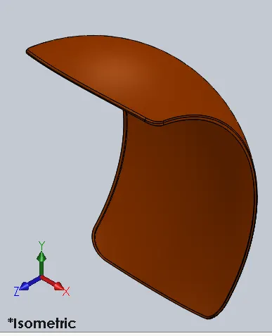
Rear Fender: Open a new part fille by Click on new select part click ok. click on the front plane and slow select the right plane to rename it as a vertical plane rear fender. similarly, we rename the top plane and right plane as center plane rear fender and midplane rear fender. Go to sketch tab click on sketch and select vertical plane front fender draw a 3point arc of radius 290 mm above the origin, set the relations that both the endpoints are horizontal and the distance between them is 364 mm and the center of the arc is vertical relation to origin at a distance of 90 mm and offset it to a distance of 6 mm inward (towards origin) then draw vertical lines in the downward direction from the ends of the first arc, now click on extend entities and select the second arc so that it intersects the vertical line at both ends and trim the extra lines. Now draw a horizontal construction line passing through the origin of length 200 mm. now exit the sketch and go to features and click on revolved boss base and select construction line as center axis and the degree of revolution in direction_1 is 10 degree and in direction_2 is 141 degrees. Now select the center plane front fender plane and go to sketch and draw a 3point arc in such a way that both endpoints are coinciding with the edges of the fender and the center is in vertical relation to origin the distance between the center and origin is 227 mm, the radius of the arc is 265 mm and exit the sketch and click on insert and select features and click on the split, select the sketch and click on the cut part and then remove the unnecessary part and click ok. Now apply a fillet of 45 mm radius by selecting all the edges of the rear fender and now apply another fillet of 4 mm radius and select outside face. Noe go-to feature tab and click on shell command and select the inside face of the fender and give the thickness to 4 mm and click ok. Now go to appearance and click on painted and click on a car and select Siena now drag it and drop it on the extrusion.
Features used to create the Rear fender:
- Sketch
- 3-point arc
- Extend
- Trim
- Revolve
- Spline
- Fillet
- Shell
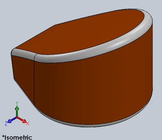
Oil Tank: Open a new part fille by Click on new select part click ok. Go to sketch tab click on sketch select top plane and at origin draw construction line passing through the origin of length 230 mm, next click on dynamic mirror entities and select the construction line draw a line of length 50 mm perpendicular and to construction line and draw an inclined line, bring the mouse back to the endpoint and it will generate an arc automatically set the other end of the arc to coincide with another end of construction line and make the center of arc coincide with construction line set a tangent relation between the inclined line and the arc now insert a point which is above the origin and it is related vertically to the origin at a distance of 146 mm and make a coincident relation with incline line. Now extrude the sketch 170 mm in direction 1 and 10 mm in direction 2. Now click on the front plane and slow select the right plane to rename it as midplane oil tank, click on midplane oil tank and sketch draw a vertical line passing through the origin of length 166 mm and now draw an inclined line in 3 rd quadrant a horizontal length 215 mm and the line makes an angle of 92.50 with vertical, draw an incline line which coincides with the edge with a vertical length from origin to the endpoint is of 42 mm and draw a two-point spline point one in the middle of the sketch and point 2 joining the vertical line the placement of point 1 is 107.5 mm horizontal distance and the 113 mm of vertical distance now extrude the sketch in two directions by selecting through all option and unselect the merc result option and click ok. Now click on insert go to features and click on the combine and select both extrude 1 and 2. Now apply a fillet of 10 mm to all edges of the tank and click on shell and give the tank thickness to be 3 mm and click ok now the solid extrusion is converted into the hollow tank. Now go to appearance and click on painted and click on a car and select Siena now drag it and drop it on the extrusion and select fillet and apply white color to it.
Features used to create the Oil tank:
- Lines
- 3-point arc
- Boss extrude
- Combine
- Fillet
- Shell
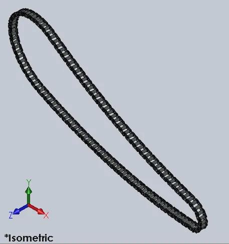
Chain Link: Open a new part fille by Click on new select part click ok. Now click on the front plane, top plane, and right plane and rename them to midplane chain, center plane chain, and front plane chain respectively. Click on midplane chain and click on sketch and at origin draw construction line passing through the origin of length 650 mm and draw a vertical construction line in downward direction of length 147 mm perpendicular to the first line. now draw two circles the larger circle of diameter 289 mm at origin as a center and smaller circle of 99 mm diameter and the end of vertical construction line as the center. Now draw two 3point curves one above and the other one below the origin with a radius of 1500 mm and the curves are acting as tangents to the circles and trim the unnecessary sketch and exit the sketch
Now select the midplane chain plane and click on sketch and draw both the inner and outer plate of the chain and make sure while we are drawing, we must not have any relation to the previous sketch. First, we are designing the outer link plate now draw a horizontal construction line of length 15.13 mm and draw concentric circles at both the end of the line of inner circle diameter 8 mm and outer circle diameter 12 mm now draw a 3 point arc both top and bottom joining both outer circles as the tangent of radius 28 mm now by the help of trim tool we can remove the unnecessary curves. Second, we are designing inner link plate again draw a horizontal construction line of length 15.13 mm and draw circles at both the end of the line of circle diameter 8 mm and select slot tool and click on both centers of the circle and draw a slot and the radius of the arc is 5.5 mm. now we need to save these sketches as a blocks select the sketch and go to tools and click on blocks and select save to save the blocks and now we can call the sketch when-ever we want and exit sketch.
Now select the midplane chain plane and click on insert blocks and insert both blocks and make relation with the first sketch select circle center of the outer link and the coincide it with the tangent point on the bigger curve and now select the other center of circle and make coincident it with 3point arc, now select the circle center of the inner plate and make it concentric with the circle of the outer plate and now select the other circle center of the inner plate and make it coincide with 3point arc now exit the sketch click on extrude and extrude the circles to a length of 20 mm over a midplane and untick the merge option and these are called pins, now select the sketch and click on extrude to extrude the outer plate of thickness 2 mm to an offset distance of 9.5 mm untick the merge option, now select the sketch and click on extrude to extrude the inner plate to a thickness of 2 mm from the vertices of the outer plate and in inward direction untick the merge option. Now we click on the down arrow of the linear pattern and click on the curve pattern option and select arc/ curve on which the pattern will be performed and give the distance between the pattern is 30.26 mm and the number of patterns to be 20 or check first whether our patter is exceeding the curve or not and select the bodies and fillets to be patterned. “REPEAT THIS PROCESS FOR ALL THE 4 CURVES” and check for overlap.
I have two overlaps first, the last pin and the first pin are over on each other, and second, the inner plate is not properly coincident with the pin. So I had deleted both the pin and the plate. And click on sketch and draw a slot and extrude it as above. Now go to appearance and click on metals and click on a car and select chromium plate now drag it and drop it on the extrusion and select fillet and apply white colour to it.
Features used to create the Chain:
- Sketch
- Circles
- 3point arc
- Slot
- Block
- Fillet
- Curve pattern
- Mirror
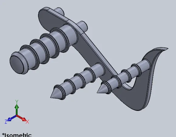
Pedal Stand: Open a new part fille by Click on new select part click ok. Go to sketch tab click on sketch select front plane and at origin draw a vertical midpoint construction line passing through origin of length 35 mm and draw another two construction line at both top and bottom end of the first construction line and both lines are horizontal and equal in relation to each other, draw two lines from the end of the horizontal construction line both above and bellow the origin and end point dimension from origin is 72 mm and both lines are horizontal and equal in relation to each other, draw an arc joining both inner ends of the line and having tangential relation with both horizontal construction line and draw an incline line from both outer end of horizontal lines and are parallelly related to each other the horizontal end point dimensions of both above and bellow line are 159 mm and 112 mm and the bottom line is 23 mm vertically downward, draw two circles of diameter of 16 mm and center to center distance of 47 mm and the centers are aliened horizontal to the origin, draw a circle of diameter 18 mm in between parallel lines at distance of 125 mm from vertical construction line, draw a circle of diameter 15 mm at distance of 218.4 mm from vertical construction line and 42 mm above the bottom horizontal construction line. Now draw a horizontal construction line at 255 mm from the origin in 1 st quadrant. Draw a spline between the above parallel line and horizontal construction line of angle 15 degrees and a load of 250 at construction line end and a load of 200 at end of the parallel line and again draw a spline between the bottom parallel line and horizontal construction line of angle 35 degrees and a load of 245 at construction line end and a load of 500 at end of parallel line. now extrude the whole sketch to a thickness of 8 mm and apply a 1 mm fillet on both faces, extrude the 16 mm diameter circles to a length of 20 mm in the backward direction.
Select top plane and click on sketch draw a vertical construction line passing through the center of 16 mm diameter circle extrusion, click on ‘L’ and draw a line horizontal line of length 15 mm and vertical line of 100 mm in the downward direction and small line towards right and incline line in the downward direction of vertical length 7 mm and a horizontal line of length 14 mm towards origin and draw a vertical line to the starting point. Now go to features click on revolve extrude and select axis to be construction line and click ok and apply a dome of 3mm and apply 1 mm fillets on the dome edge and end of 20 mm extrusions. Now select the 18 mm and 15 mm circles in sketch 1 and extrude them to a length of 100 mm from the outer surface and apply distance chamfer of 16 mm and 9 mm to 18 mm diameter rod and 16 mm and 7.5 mm to 15 mm diameter rod.
Select the outer face of the pedal and click on sketch and draw an offset circle of 2 mm, and another two circles of 2.5 mm. and extrude it to a length of 2.5 mm at an offset distance of 20 mm and apply 1 mm fillet of both the faces. Now click on the linear pattern and select the fillet and extrusion over an edge at a distance of 20 mm and no. of patterns to be 4. Now we get the same extrusions 4 times with equal distance between them and apply 1 mm fillet at the start of all three rods.
Features used to create the Pedal:
- Sketch
- Lines
- Circles
- Fillet
- Revolve
- Dome
- Chamfer
- Linear pattern
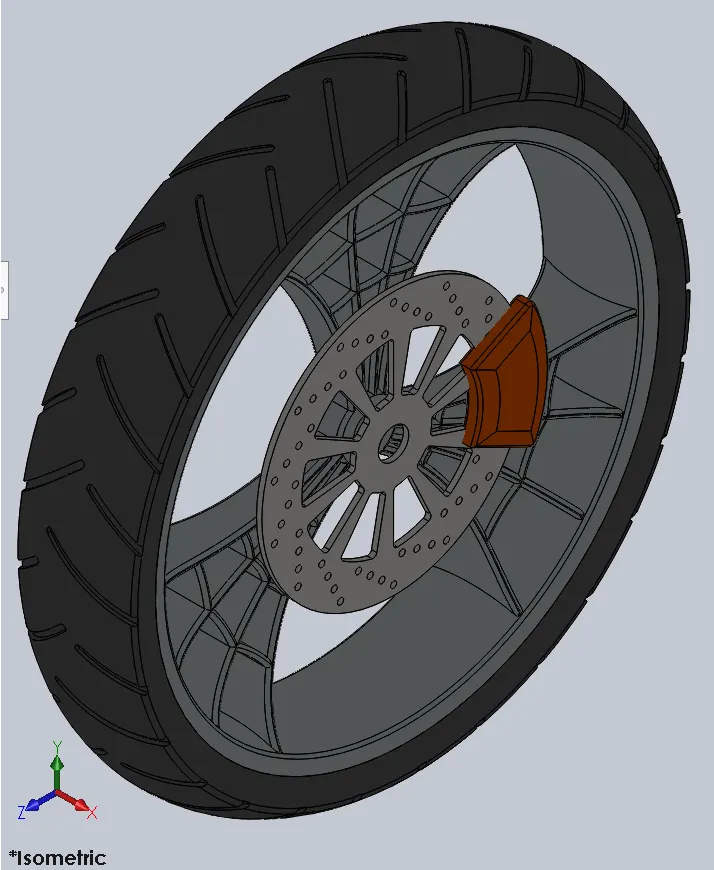
Front Wheel:
- Rim:
Select front plane and click on sketch and draw a rectangle above the origin of dimensions 110 mm*40 mm, where the origin coincides with the midpoint of the 110 mm line, now draw a horizontal line of 140 mm above the origin at a distance of 330 mm the midpoint of the line coincide with the origin and now draw two incline lines at the ends of the horizontal of 75 degrees with respect to horizontal line and the endpoints of the inclined line are allied horizontal, then draw a 3point arc joining these endpoints of radius 230 mm and apply fillets of radius 5 mm at the corners and exit the sketch and go to features click on revolved boss base and select the 110 mm line as a reference line and revolve to get the outer frame of the rim.
Select the right plane and start sketching draw two construction lines passing through origin one line is vertical and other is 2 nd quadrant making an angle of 31 degrees to the vertical line, now draw a horizontal line passing through the origin of length 22.5 mm, draw a spline joining the endpoints of angle construction line and horizontal line, make a relation by activating lower part of the spline as vertical and apply a load of 340. Now draw a 3point arc by joining the end of the spline and vertical construction line to make that arc fully define make a concentric relation between the arc and the origin. Now click on mirror entities and select spline horizontal line and 3point arc to be mirrored over the vertical construction line and exit the sketch and extrude it over a midplane of length 122 mm click ok.
Select the right plane and click on sketch and click on convert entities and select the extrusion and click ok, now click on offset entities and select curved line and horizontal line and set the offset distance to be 9 mm inward direction. Now draw two vertical construction lines between two horizontal lines the distance between the lines is 9 mm and the first line is 2.5 mm away from the origin and draw two construction lines passing through the origin one line is vertical and the other is 2 nd quadrant making an angle of 9 degrees to the vertical line, now draw two splines from the two intersection points on horizontal to the outer arc the distance between the splines is 9 mm both splines have a load of 300 and the bottom end of the splines is activated to make a vertical relation. Now mirror entities and splines to mirror it over the vertical construction line now exit the sketch and click on extrude cut select through all both in direction 1 and 2 and select contours and select extrude in feature scope and click ok.
Select the right plane and start sketching draw three concentric circles of diameter 215 mm, 350 mm and 485 mm respectively now select the circles and make it as construction geometry. Now click on offset entities and select the curves to an offset distance of 4.5 mm now select these curves and make it as construction geometry. Now trim the unnecessary curves if we observe there are some coincident points between the curves and the circles we have to draw 3point arc’s joining these points the arc’s on the circle of radius 485 mm are of radius 200 mm, the arc’s on the circle of radius 350 mm are of radius 75 mm, the arc’s on the circle of radius 215 mm are of radius 20 mm and 15 mm. click on offset entities and select all the 3point arcs and offset them to an 8 mm distance. Now join the openings by drawing line and trim the unnecessary curves and exit the sketch now click on extrude boss base and make extrusion up to vertex and select the vertex in both the directions, select the contours and select the extrude cut in feature scope and click ok.
Select the front plane and click on sketch and draw a vertical construction line passing through the origin, click on interception curve and select the edge of the rim and delete the bottom curve, now draw a horizontal line coinciding with the edge the distance between the starting point to the vertical construction line is 20 mm and draw a vertical line coincide with the edge draw an inclined line from the vertical line joining the curve and make the relation to be tangent and select the curve and make it as a construction geometry. Now draw a spline in between the starting point of the horizontal line and end od vertical line activate both ends of spline the lower end is vertical and a load of 525 and the upper end is tangential and a load of 150 now click on mirror entities select the sketch and mirror it over the vertical construction line and exit sketch. Click on revolve cut and select the horizontal line as axis of revolution and click ok.
Now click on circular pattern select any circular edge and select bodies and select the number of patterns to be 3 and click ok.
Click on the combine and select add and then select the outer circle of rim and webs and click ok.
Rotor:
Select the right plane and start sketching draw two circles of diameter 345 mm and then extrude it by an offset distance of 45 mm and extrude thickness of 7 mm. Now select the outer face of the circular rotor and click on sketch and draw a circle of diameter 8 mm which is 160 mm away from the origin and a vertical relation between the center of circle and origin, now click on the linear pattern then give the distance between the pattern is 20 mm and the no of patterns is 4 and the angle is 340 degree and go to features and click on extrude cut and the cut is up to next surface and click ok, click on the circular pattern and select any circular edge for reference and the number of patterns to be 15 and click ok. Select the outer surface and click on sketch and draw two concentric circles of diameter 100 mm and 243.52 mm. Now draw two lines that are separated by 25 degrees and are coincident relation with the origin and apply 5 mm fillets on all four edges. Click on extrude cut and the cut is up to the next surface and click ok, click on the circular pattern and select any circular edge for reference and the number of patterns to be 10, and click ok. Again select the right plane and start sketching draw two circles of diameter 40 mm and then extrude cut it as through all both sides and click ok.
Caliper:
Select the right plane and start sketching draw two concentric circles of diameter 200 mm and 380 mm and draw a construction line vertical passing through the origin. Now draw two lines that are separated by 54 degrees and are coincident in relation to origin to make the lines fully define we add one more dimension the angle between the construction line and the first line is 63 degrees and now trim out the unnecessary curves. Click on extrude and extrude it over a length of 19.5 mm in direction 1 and 10,5 mm in direction 2 and click ok. Now apply distance-distance chamfer of dimensions 6 mm and 20 mm to both large faces, apply 8 mm on the outer edges of the caliper, and apply 4 mm fillet on chamfer edges on both sides.
Tire:
Go to sketch tab click on sketch select front plane and click on convert entities drop done and click on intersection curve and select outside face of the rim click ok. Now delete the bottom curve. Click on ‘L’ and draw two incline lines at either end of the curve and make an equal relation between them and make the endpoints to be horizontal and draw a 3point curve joining the endpoints and of length 154 mm the radius of 213 mm and make a vertical relation between center of the arc and origin and the distance between them is 280.7 mm, apply 7 mm fillet at the endpoints. Now click on show hidden axis and exit the sketch. Go to features and click on revolve extrude and select the center axis as a reference and select sketch click ok.
Now we have to make tire grip. Select the front plane and click on sketch select the edge of the rin and click on convert entities, select ‘3 point center rectangle’ and draw two rectangles on the left side the bigger one above and the smaller one below the origin make a relation that both rectangles are parallel and the breath of two rectangles is equal to a length of 8 mm and the length of the larger rectangle is 138 mm, length of a smaller rectangle is 90 mm. Now we make some relations to constrain the geometry the rectangle makes an angle of 130 degrees between the rectangle and the edge of the rim, the horizontal and vertical distance between the bottom vertex of the bigger rectangle and origin are 20 mm, 50 mm respectively, similarly the horizontal and vertical distance between the top vertex of smaller rectangle and origin is 25 mm, 29 mm respectively. Now we select ‘3 point center rectangle’ and draw two rectangles on the right side the bigger one above and the smaller one below the origin make a relation that both rectangles are parallel and the dimensions are equal to the previous two rectangles. Now we make some relations to constrain the geometry the rectangle makes an angle of 50 degrees between the rectangle and the edge of the rim, the horizontal and vertical distance between the bottom vertex of the bigger rectangle and origin are 54 mm, 63 mm respectively, similarly the horizontal and vertical distance between the top vertex of smaller rectangle and origin are 96 mm, 46 mm respectively and exit the sketch. Now click on extrude cut and select offset of 450 mm and the cut must be performed at ‘offset from the surface’ and the distance is 4 mm and select the tire in the feature scope and click ok. The above 4 mm is the depth of tire grip. Now apply a 4 mm fillet on the edges of the rectangular cut. Select the extrude cut and fillet and click on circular pattern select any one circular edge and select the number of instances to be 14 and click ok.
APPEARANCE:
Go to solid bodies and rename it to be tire and now click on appearance and click on metal and click on chrome and select chrome plate now drag it and drop it on the extrusion and click ok.
Go to solid bodies and rename it to be the rotor and now click on appearance and click on metal and click on a steel and select carbon steel now drag it and drop it on the extrusion and click ok.
Go to solid bodies and rename it to be caliper and now click on appearance and click on painted and click on a car and select Siena now drag it and drop it on the extrusion and click ok.
Go to solid bodies and rename it to be tire and now click on appearance and click on rubber and click on a matte and select matted rubber now drag it and drop it on the extrusion and click ok.
Features used to create the Front wheel:
- Sketch
- Lines
- 3 point arc
- Sketch fillet
- Revolve
- Spline
- Extend
- Trim
- Cut extrude
- Offset
- Revolve cut
- Circular pattern
- Chamfer
- Fillet
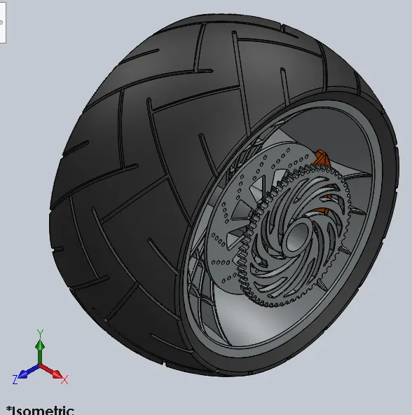
Rear Wheel: The design of the rear wheel is same as front-wheel except there is a change in dimensions, rotor design, grip on tire.
Features used to create the Rear wheel:
- Sketch
- Lines
- 3-point arc
- Sketch fillet
- Revolve
- Spline
- Extend
- Trim
- Extrude cut
- Offset
- Revolve cut
- Circular pattern
- fillet
Front Fork:
Fork:
Create a new part file and select the front plane and sketch and start by drawing a horizontal line from the origin going to left to a length of 1330 mm, from the end of the line draw a vertical line of radius 30 mm and then a horizontal line and an incline line and again a horizontal line of length 485 mm and the vertical radius between the horizontal line and the first line is 25 mm, and draw an incline line of 50 mm horizontal distance joining the origin. And apply the length of the 505 mm from starting the incline line to the origin to fully define the sketch and now go to features and click on revolve boss base and select 1330 line as axis and revolve the component.
Triple clamp:
Select the flat circular end of the extrude and click on the sketch to select the circular edge and click on convert entities and draw another circle from the origin of diameter 75 mm and draw another circle of diameter 80 mm which is placed at the height of 100 mm and 105 mm away from the origin. Draw a line joining both ends of the diameter and draw a vertical line from the bottom end of the 80 mm diameter circle until 24 mm below the origin and draw a horizontal line joining the 75 mm circle and draw an incline line joining the 1 st quadrant point of top circle and the top point of the bottom circle now trim the unnecessary curves and extrude the sketch to offset of 20 mm in the direction of origin and extrude length of 40 mm and click ok. And now apply a fillet of 5 mm on all the edges except the flat edge. Now select the temporary axis option and click on the linear pattern and select the horizontal axis as a reference and select the bodies to be patterned, at a distance of 240 mm and the number of instances to be 2. Now turn off the temporary axis.
Axil:
Select the front plane and click on sketch and draw a circle of diameter 40 mm has a horizontal relation with the origin at a distance of 70 mm and click on extrude and select up to the surface and select the flat end of the triple clamp and we only merge it with the fork.
Steering stem:
Select the upper face of the lower triple clamp and click on sketch and draw a circle of diameter 50 mm which is concentric to the 80 mm circle now draw a line from upper quadrant to lower quadrant and make it colinear with the flat face and trim the left side click on extrude and select up to next and merge it only with the triple clamp.
Headlight bucket:
Select the front plane and click on sketch and draw a horizontal construction line of length 61 mm from the center of the fork now draw an incline line above the construction line at a distance of 18 mm and towards the bottom now a draw a perpendicular line of length 54 mm and constrain the geometry by adding the horizontal dimension from the top point of the incline line to the top point of the perpendicular line of length 208 mm and the angle of inclination is 28 degree to the construction line now draw a construction line at the end of the perpendicular line and make it perpendicular. spline joining the top point of the incline line and the end of the perpendicular line and make the perpendicular line a tangent. Now go to features and revolve the sketch and do not marge it with any part. Click on insert and click on features and click on move and select the body and move it in z-direction -48 mm. Now select the outer face and start a sketch clock on offset entities and select the circular face to be offset Ed 4 mm in inward direction now click on extrude cut of 10 mm with a draft of 5 degrees and remove the autoselect and select headlight bucket, apply 3 mm fillet to the outside edge of the bucket and click on the dome and select the inner surface and the radius of the dome is 7 mm, apply 1mm fillet on the inside edge. To get more deviations between the face of the lens of the headlight and the bucket. Now select the move-in feature tree and drag it down below the fillet and bring the end of the feature tree up now this puts us back and now we can sketch on the dome face now click on intersection curves and select dome and inner face and click ok and select the lines and make then construction geometry and draw another construction line to revolve the cut and now click ‘L’ and draw line at the end and make it colinear with the line to maintain the draft angle and draw a line from the end and to the curve and to the outside and join it at the midpoint of the line and back to where it start make the outside point line and midpoint line perpendicular and set the dimensions and select the revolve cut and click ok. Now move back the move command to its original position.
Handlebars:
now we select the upper triple clamp and start a sketch and draw a circle of diameter 35 mm and it is 50 mm away from the flat plane and 24 mm up from the bottom plane and exit the sketch. Now select the top plane and click on sketch and draw spline from the center of the circle towards down and draw an incline line in the same direction and set dimensions to fully define the sketch and make spline tangential and a load of 200 at one end and horizontal and a load of 425 at other end and exit the sketch and now select the front plane and click on sketch select the straight line from the previous sketch and make it as construction geometry now draw a spline from the center of the circle and the endpoint is in vertical relation to the endpoint of construction line and the distance between them is 119 mm and the spline at the circle center is horizontal and a load of 300 and exit the sketch and go to curves drop down and click on projected curves and select sketch on the sketch and then select sketches and click ok and now sweep the circle over the new curve and merge it only with triple clamps.
Handle grip:
select the circular face and click on sketch click ‘L’ and draw a horizontal line passing through the center of the circle now to fully define click on convert entities and select the circular face and click off and make the circle as construction geometry and make the center of the circle to merge with the line now exit the sketch and we use this to create a reference plane select the circular face and the line to fully define the plane. Now select the new plane and start sketch on it draw a vertical line from the center of the circle of length 154 mm and draw 4 3point arcs the 1 st the first one is big and the radius 100 mm and the remaining three are equal in a radius of 35 mm and are aligned vertically draw construction lines joining the three 3point arcs draw an incline line at the end of 3point arc coinciding with the circle and a horizontal line back to origin and to fully define the sketch the distance between the vertical line and the construction line is 24 mm. now click on revolve boss base and select the vertical line as the axis and click ok. Again, select the new plane and click on sketch and draw a vertical construction line in the downward direction of length 15 mm then draw a corner rectangle at the end of the construction line of dimensions 55 mm* 25 mm and click on revolve boss base and select the vertical line as axis and click ok. Turn on the temporary axis and click on create new reference plane by selecting the plane and axis and the angle of the plane is set to 160 degrees and click ok. Turn off the temporary axis. Select the new plane 2 and start sketching draw a horizontal construction line of 15 mm and click ‘L’ and draw a line to the end on the cylinder and draw a 60-degree incline line with horizontal of length 84 mm, draw a horizontal line of length 174 mm from the end of incline line now draw an incline line of 70-degree angle to the horizontal upward and draw an incline line of 109 degrees and another incline of 105 degrees with the horizontal and extrude the sketch at the midplane of length 15 mm and it will be merged with handle, now apply 25 mm fillet to outside edge and 5 mm fillet to the inside edge and apply 4 mm fillet to two edges of revolve and to all the external edges on the external side of the lever.
Cable:
select the side face of the lever and start the sketch draw a construction line from the midpoint of the edge of length 25 mm horizontally and set a relation that the line is parallel to the edge to fully constrain the geometry and draw a circle of diameter 9 mm at the end of the construction line and exit the sketch. Select the top plane and click on sketch draw a spline from the center of the circle to point in between the handle bar and the fork extend and click esc and draw a horizontal line of 10 mm the d=vertical distance from center of the circle to the point is 227 mm but the line is still moving select the other end of the spline and make coincident between the spline and the circle center make the spline and the 10 mm line as tangent and at a load of 400 and the other end is at a angle of 120 degree to the construction line and at a load of 600 exit the sketch right plane and click on sketch select the spline from the last sketch and convert it in to a construction geometry now draw a spline from the right end to the circle center and activate the upward handle and make an angle of 160 degree and a load of 275 and exit the sketch and go to curves drop down and click on projected curves from these two sketches and click ok and sweep the circle over the new curve and merge it only with handle bar and triple clamp and click ok.
Appearance:
Select a part and click on appearance and go to metal and click Chrome and select polished chrome.
Select the handle grip and cable and click on appearance click on rubber and select gloss rubber.
Select the dome face and chamfer cut and click on appearance click on the light and click on area light and select area light, go to advance tab and set the luminous intensity to 1 and click ok.
“NOW MIRROR ALL THE BODIES ON THE FLAT FACE OF THE TRIPLE CLAMP”
Now click on the combine and select two forks and click ok and again click on the combine and select both the handles and click ok.
Now select the top plane and click on the reference plane in the drop-down of planes select the axis of axil and set an angle of 59 degrees and click ok. It will create a new plane 3 and click on the normal view to plane 3.
Now click on view orientation dropdown and click on new view and name it as the front of the bike and click ok.
Features used to create the Front fork:
- Sketch
- Lines
- Revolve
- Circle
- Fillets
- Linear pattern
- Spline
- Extrude cut
- Dome
- Curve
- Sweep
- Plane
- Mirror
- Combine
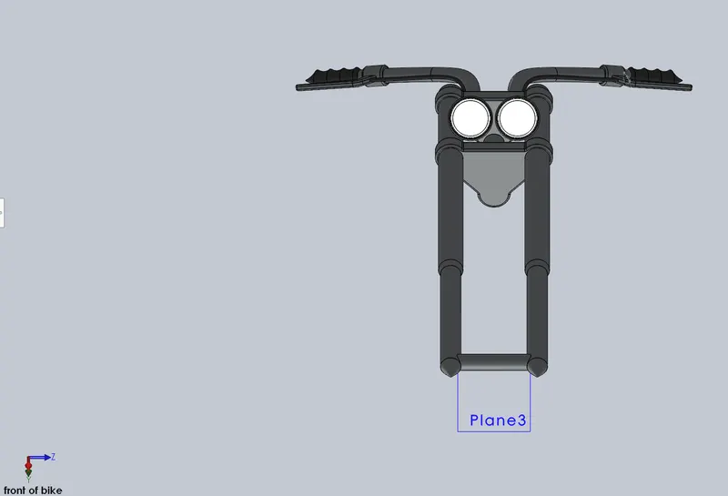
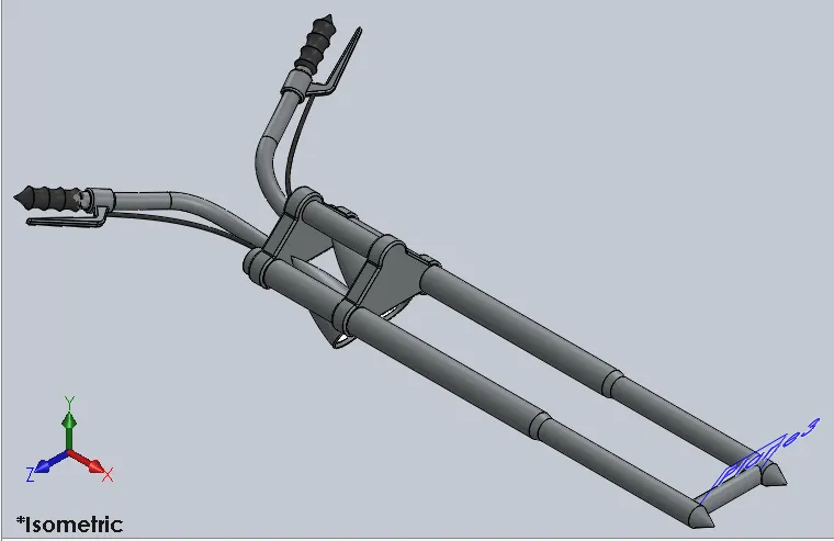
Chassis: Create a new part file and rename the planes top plane as bottom plane chassis, front plane as midplane chassis select midplane chassis and start a new sketch import a sketch picture by clicking on tools click on sketch tools and click on sketch picture and select the picture and import it to solidworks we can position the sketch picture by giving in put coordinates x=-930 mm, y=-805 mm and deselect the scale tool and set transparency to full image to minimum of 0.50 and click ok, we can also rename it to blueprint chopper. Start a new sketch on midplane chassis and draw concentric circles of 4 mm offset and a outer circle of radius 40 mm and now we position the circle to fully-define it 880 mm horizontal distance from origin and 185 mm vertical distance from origin. Start another sketch on midplane chassis draw a horizontal line passing through origin of length 710 mm and draw a spline at the end of it which is in tangential relation to line and of weight 200. Select the bottom plane chassis and draw a line starting from origin and parallel to the previous line at a distance of 165 mm and draw a spline at the end of it where the upper handle is in tangential relation to line and of weight 225 and bottom handle is vertical and of weight 350. Now exit the sketch and go to surface and click on curves and select project curves and select sketch on sketch, and select both the curves in bottom plane and midplane chassis and click ok. Now it is gone generate a new curve in right plane which we cannot control in order to change the curvature select the right plane click on sketch and daw a spline and dimension it as horizontal point is 165 mm away and the upper handle is of weight of 215, create a new sketch of third sketch by help of convert entities now exit the sketch and go to surface and click on curves and select project curves and select sketch on sketch, and select both curves and click ok. Now hide the first curve and click on sweep boss base and select the sketch and the curve2 and click ok. Click on mirror and select the midplane chassis as reference and select the sweep and click ok.
BACK PLATE: Select the right plane and start sketching and draw a circle of diameter 275 mm vertically above the origin and draw a construction line from the center of the circle to the bottom of the origin and select the outer circle of the tube and click on convert entities and draw a horizontal line from the bottom quadrant of first circle to second circle and further as a tangent and make the other end of the construction line to coincide with the horizontal line and give proper dimensions. Draw a vertical line of 85 mm on the other end of horizontal line and draw some lines in a form of semi ‘ I ‘ section and fully-define it. Now draw a tangent line joining the bigger circle and left side smaller circle and make sure the points intersect and trim the unnecessary curves. Now exit the sketch and click on extrude and give a dimension of 22 mm and select merge results. Select the outer surface of extrusion and click on sketch select the right-side edge and left side tangential edge and offset it 50 mm in inward direction and now draw two horizontal parallel lines which are located at a bottom line at a distance of 30 mm and upper line at a distance of 220 mm away from origin and extend the right-side edge and trim the unnecessary lines and exit sketch and click on extrude cut and select “up to next” and click ok. Now add a distance-distance chamfer to lower right-side edge of 90 mm and 44 mm, add a 25 mm fillet on top and inner edges, add 50 mm fillet to two remining side edges. Create a new plane by selecting first reference as midplane chassis and second reference as top point on the outer curve and click ok. Start the sketch on the outer surface draw two concentric circles at the same center of the curve of offset distance of 5 mm and 4 mm. select the plane and sketch the spline one end is at the center of circle and other end is at 303 mm above the origin and 411 mm away from origin and weight of spline is 350 we click on sweep by selecting the curve and the circle and click ok and now repeat the same process for lower tube only the spline is at 69 degree and weight of spline is 465.
AXIL: on the new plane start sketching of circle of 95 mm diameter located at a horizontal distance of 426 mm and a vertical distance of 280 mm and extrude it over midplane of thickness 44 mm, select merge results and click ok. Select the inner surface of axil and click on sketch draw a circle of diameter 60 mm and it is concentric with axil and extrude it for a length of 223 mm select merge results and click ok. Apply dome of 10 mm to the outer surface of rim.
Select the midplane chassis and click on sketch and draw a horizontal construction line of 215 mm passing through origin and 3-point spline starting from the end of construction line place the points approximately based on the blueprint the second and third spline point at vertical distance of 700 mm and 785 mm respectively, the second and third spline point at horizontal distance from origin of 500 mm and 1143 mm respectively. Now activate upper right handle and make it horizontal and weight of 1000 and activate bottom left handle and make a angle of 55 degree and a weight of 1500. Create a new plane by selecting the spline and top right point (third spline point) as reference and click ok. Select the new plane and draw a concentric circle of diameter 32 mm and 40 mm and make pierce the center of circle and the origin (third spline point) click on sweep and select the spline and sketch and click ok. Click on split and select the outer surface of back plate and remove the extra sweep by selecting the consume cut bodies and click ok. Start a new sketch on midplane chassis first click on convert entities and select the intersection circle and click ok and draw a spline from the center of the circle to top, draw a horizontal construction line at top point and give dimensions to spline the lower handle is vertical and of weight 400. The top point is located at a horizontal distance of 295 mm, vertical distance of 576 mm and the activate top handle and the spline angle 48 degree to horizontal construction line and a weight of 825. Create a new plane by selecting the spline and center point and click ok. Select the new plane and click on sketch and draw two concentric circles of offset 4 mm and outer circle dimeter is 40 mm and make pierce with spline exit the sketch click on sweep and select the spline and sketch, deselect merge results and click ok. Click on split and select the outside surface and select the body to be removed and select consume cut bodies and click ok.
STEARING STEM: select the midplane chassis and start sketching draw a vertical construction line and 59 degree incline construction line of length 200 mm and make it fully-define and now draw a rectangle parallel to the incline construction line of same length and breadth of 7.5 mm and 32.5 mm away from the incline construction line and make the end points of rectangle and end points of incline line coincident in relation now exit the sketch and revolve the sketch over an incline line as axis, de select the merge results and click ok. Click on split and select the outside surface and select the body to be removed and select consume cut bodies and click ok. Click on combine all the bodies and click ok.
CONNECTING PLATES: select the midplane chassis and start sketching draw a continuous lines of length 102 mm, 102 mm, 135 mm, 120 mm, 135 mm and the last lime make sure it is coincided with the other end. Make alternate lines as construction line and make offset of 6 mm for remaining lines and join the ends by a small line and now extrude the rectangle up to next on both directions and click ok. Add 2 mm fillet to the outside face of the head tube.
LOCATE THE FOOT REST: select the midplane chassis and start sketching draw a right-angle triangle of base 210 mm and a vertical line of height 85 mm at the end of the tube. Now draw a construction line parallel to hypotenuse of length 47 mm and upper point is 20 mm away from the vertical line and 30 mm below the upper edge. Now draw circles at both end of the line of diameter 16 mm exit the sketch and extrude it at a offset distance of 165 mm and for direction 1 we do midplane extrude of 10 mm and deselect the merge results and click ok. Click on split and select the outside surface and select the body to be removed and select consume cut bodies and click ok. Add 20 mm fillet to the upper edge and 1 mm fillet to outside edges and holes. Click on mirror and select the body and select the reference plane to be midplane chassis and click ok and combine all three bodies.
FOOT STAND: select the side face of the vertical and start sketch select the circular edge click on intersection in convert entities and remove unnecessary curves and draw a vertical construction line passing through center of circle and draw a incline line of length 50 mm making an angle of 120 degree to the vertical construction line and a 4 mm offset for the incline line in bi-direction with line caps and make the base line as construction. Click on trim and remove the unnecessary curves and lines and click ok and extrude it to a length of 40 mm in backward direction. Add a round fillet to the outer side, add 3 mm fillet of top and bottom face of incline plane, all the inner and outer edges of back plate, axil. Select the top surface of incline plate and start sketch draw a circle of diameter 12 mm and draw a construction line from center of circle to midpoint of the curve of length 10 mm and make sure the line is vertical and exit sketch, click on extrude cut up-to next. Add a reference plane select first reference to be bottom plane and second reference is in 308 mm upward direction and click ok and rename this plane to “bottom plane fuel tank”. Change the appearance of the part go to appearance click on painted, click on car and select Siena and click ok.
The chassis is the main frame of the chopper. It holds all the components such as front fork, pedals, kickstand, oil tank, engine, gas tank and rear wheel. It supports all the components and supports to the bike. The modelling of chassis starts with using chopper image for reference. It uses features such as extruded boss, splines, and revolving parts, making mirror and sweep. At the end whole part created by using fillet and it gives nice appearance to the chassis and the sharp edges gets round. The appearance given to the chassis is sienna color i.e. bright orange color.
Features used to create the Chassis:
- Blueprint sketch
- Splines
- Projection Curves
- Mirror
- Extrude
- Extrude cut
- Chamfer
- Dome
- Split
- Revolve
- Combine
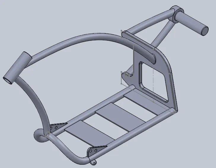
Engine: TRANSMISSION SYSTEM: Create a new part file and select front plane and start a new sketch import a sketch picture by clicking on tools click on sketch tools and click on sketch picture and select the picture and import it to solidworks we can position the sketch picture by giving input coordinates x=-1493 mm, y=-965 mm and deselect the scale tool and set transparency to full image to minimum of 0.50 and click ok, we can also rename it to blueprint engine. Select the front plane and click on sketch and draw a concentric circle of diameter 200 mm and 80 mm at the origin and another circle of 130 mm diameter 350 mm in left side to the origin now draw upper and lower tangents to the circles and make lower tangent horizontal now exit the sketch and click on extrude select all the circles and give midplane extrude of 200 mm. now select sketch and click on extrude and select the concentric circles and select from surface 50 mm extrusion, now select sketch and click on extrude and select the 80 mm circles and select from surface 40 mm extrusion. Start a new sketch on front plane start drawing the back end of the engine click on ‘L’ and draw a pentagon and vertical construction line passing through origin and position all the points of pentagon and extrude this sketch over midplane of length 150 mm select merge results and click ok. Add a 50 mm fillet to all the edges of pentagon extrusion.
BELT PULLY: select the right plane and start sketching draw a horizontal line of 102 mm from the edge of the surface and a vertical line of 70 mm and a horizontal line of 2 mm in inward direction, a vertical line of 10 mm in downward direction, a horizontal line, a vertical line of 10 mm in upward direction, a horizontal line of 2 mm and vertical line in downward direction and a horizontal line of 10 mm coincide with the edge and a vertical line of 40 mm to close the sketch and click on revolve extrude and select the sketch and 102 mm line as axis and click ok. Create a new plane by selecting right plane as first reference and the back vertex as second reference and click ok. Select the new plane and start sketch turn on temporary axis option and draw a pully colinear to the axis draw a line and make it colinear with temporary axis and the end of first pully now draw a vertical line of 80 mm, a 2mm horizontal line in inward direction, a 10 mm vertical line in downward direction and a horizontal line, a vertical line of 10 mm in upward direction, 2 mm horizontal line, a vertical line in downward direction, horizontal line and a vertical down ward line of 40 mm to close the figure and revolve extrude as horizontal line as axis. Now select the inner surface of the first pully and click on sketch and click on convert entities and select both the circles a select them and convert them to construction now draw a center point rectangle on the top quadrent point of dimensions 5 mm*4 mm, exit the sketch and extrude it up to the surface and select the inner surface of outer part of the pully and click ok, click on circular pattern and select the circular edge and the number of 40 patterns and click ok and follow the same process on the back pully and the number of patterns to 44 and click ok. The difference in teeth is to maintain the same pitch. Add 10 mm dome on outside of both pullies.
Select the front plane and click on sketch click on offset entities and select the outer circle of the first pully then offset it in inward direction of 30 mm. draw a circle of 10 mm diameter the center of the circle is 55 mm vertically above the origin click on circular pattern and select the circle and number of instances 12 make circular pattern coincide with origin, exit the sketch and click on extrude cut and select the offset 250 mm and set a 3 mm offset from surface and click ok. Repeat the same process on back pully except the circle is located 65 mm vertically above the origin. Add a 3mm chamfer to inside dome faces, add 1mm fillet to out side surfaces of both pullies.
Select the front plane and click on sketch and draw a horizontal construction line passing through origin of length 155 mm and at the end draw the circle of diameter 90 mm, draw a horizontal line above and below construction line and draw a vertical construction line of 50 mm joining both the lines and make the midpoint of vertical construction line coincide with horizontal construction line. click on convert entities and select the circular edge and click ok and click on trim and remove the unnecessary curves and lines. Extrude the circle over a midplane of length 150 mm again select the sketch and select the small area extrude it over a midplane
CYLINDERS: Select the front plane and click on sketch and draw a incline line of 102 mm and draw a continuous line of 240 mm and fully-define the line by making the line to Have 64 degree inclination to top plane. Now create a reference plane by selecting the line as first reference and the outer point as second reference and click ok. On this new plane start a new sketch draw a center point rectangle of dimension 190 mm*190 mm now extrude this rectangle up to vertex and select bottom vertex and add a 7.5-degree draft and click ok. Select the bottom surface of draft rectangle and click on sketch and draw a center point rectangle of dimension 100 mm*100 mm click on extrude select up to next and click ok. Now we select the previous extrude of 190 mm* 190 mm and inwe extrude it in 125 mm in direction 2. Add a distance-distance chamfer on all 4 top edges of 125 mm extrude of distances 90 mm and 15 mm, add a 15 mm fillet on 4 top edge, side edges up to bottom, bottom face edges and click ok. Select the new plane and click on sketch and draw two concentric rectangles of dinensions 120 mm* 120 mm and 220 mm*220 mm and add 10 mm fillet to all inner edge of 120 mm rectangle. Now click on extrude cut and select offset 26 mm and cut of 8 mm click ok. Click on linear pattern and select the incline line of 240 mm as reference and the distance between the pattern is 16 mm and the number of instances is 14 and click ok. Add 2 mm fillet to all internal and external edges of fins, add 10 mm fillet to outside edge of engine case and stater, add 5 mm fillet to all the edges that connect stater motor to the engine, add 8 mm fillet to edges that connect cylinder to rest of the engine. Select the outside upper of cylinder valve cover and click on sketch draw a construction line joining midpoint of both edges now draw 3-point center rectangle at the midpoint of the construction line of dimensions 100 mm* 25 mm, add a fillet of 10 mm to all corners and extrude it for 2 mm, add a dome of 2.5 mm on the outer surface and deselect the continuous dome option. Now mirror the boss extrude and dome across the front plane.
SPARK PLUGS: Select the front plane and click on sketch and draw a line from the midpoint of the cylinder head in downward direction, a horizontal line of 35 mm, a vertical line of 30 mm, horizontal line, a 10 mm vertical downward line, horizontal line to the cylinder head and a vertical line to join the midpoint and apply dimension to fully-define the sketch and extrude that over a midplane of 20 mm width, add 10 mm fillet to all outer edges, add 2.5 mm fillet to top face and vertical edges.
Click split and select the upper surface of transmission system and click on cut parts and select the cylinder and deselect consume cut bodies and click ok.
Click on mirror select the right plane as reference and use bodies to mirror and deselect the merge results and click ok. Add 25 mm fillet on outside edge of the case, add 4 mm fillet to the boss that extent from outside case.
MOUNTING POINTS: select the bottom face and click on sketch draw vertical and horizontal construction lines passing through midpoint of the bottom plate now draw a rectangle of dimensions 75 mm*15 mm and it is positioned in second quadrant 90 mm away from vertical construction line and 10 mm bellow the top edge of bottom face, extrude it to a length of 50 mm in downward direction. Now select the bottom of the rectangular faces click on sketch and click on convert entities and select the bottom edge of rectangle and draw a continuous line of 10 mm to bottom edge on both sides and 40 mm vertical lines on both end of the 10 mm line and join the vertical line with a horizontal line to close the sketch, extrude it to a length of 12 mm in downward direction, add 5 mm fillet to all the edges except the bottom face and click ok, now mirror all the above extrusions and fillet over both vertical and horizontal construction lines joining mid points.
SPROCKET: select the front face of transmission system click on sketch draw a 40 mm diameter concentric circle and extrude it over a length of 85 mm and select the end face of circle and click on sketch and draw two concentric circles of diameter 20 mm and 110 mm and extrude it to a width of 15 mm, add 4 mm chamfer to outside edges of 15 mm extrude. Select the outside surface and click on sketch and draw a concentric circle of diameter 99 mm, make it construction and draw a 9 mm circle on the circumference of the 99 mm diameter circle and draw a vertical construction line of length 15 mm from center point of the 9 mm circle draw a midpoint line at the end of construction line of length 17 mm now draw a tangent lines to the 9 mm circle from the end points of midpoint line now click on extrude cut up to next and select all the counters click ok, add 2.2 mm fillet on outside edges. Now select both extrude cut and fillet and click on circular pattern of 21 instances, add a distance-distance chamfer of 24 mm and 75 mm to the inner surface of the sprocket, add 5 mm chamfer to smaller outer edge of sprocket.
INTAKE: start a new sketch on front plane and draw a vertical construction line of 350 mm from the origin, draw another incline line which makes 20-degree angle with the vertical construction line of same length and draw a arc 375 mm from the end of incline construction line whose end points are horizontal and have midpoint mate with arc and vertical construction line. Start a new sketch on right plane and draw two concentric circles of 4 mm offset and outer circle diameter of 45 mm at the end of vertical construction line as center now select the sketch and sweep it over the arc by deselecting the merge results and click ok and mirror the sweep over right plane. Now combine both the sweeps, both the cylinders and rest of the engine click ok. Select the front plane and click on sketch and make show sketch 22 and take the point as the center oof the circle and draw a circle of diameter 45 mm. now create a new plane over first reference is top plane and second reference is center point of circle and click ok. Start a sketch on new plane draw a vertical line starting from origin and then draw a arc of radius 140 mm and line at the end of the arc make the end line and the vertical line tangents to arc and make end line horizontal and to fully-define the sketch give some dimensions, now use the sweep option to sweep the circle along the arc. Start the sketch on the new plane and draw a horizontal line of length 128 mm at the center of the circular face and draw a vertical line of 56 mm and draw two splines and fully-define the sketch and click on revolve and select the sketch and revolve it over 128 mm horizontal line. add a 5 mm fillet on back and outer edge. We add more detail by extrude cut and circular pattern operation.
EXHAUST FOR FRONT CYLINDER: Start a new sketch on front plane, show the center line of cylinder sketch and convert it and make it as construction geometry draw a 100 mm line at 1 mm bellow the end point of construction line and which is in perpendicular relation to the construction line. Draw 25 mm arc at the end of 100 mm line having a tangent relation, draw a line which acts as tangent to the arc and parallel to the construction line, draw a 3-point arc at the end of the line and make a tangent relation between them now draw a line at the end point of the arc and make a tangent relation between them and the angle between the two lines is 80 degree and make the arc center co inside with transmission dome again draw a 3-point arc of radius 150 mm and draw a line at the end of the arc and make a tangent relation with both lines and the angle between the lines is 110 degree and then fully-define the sketch by positioning the end point of the line. and make first line, arc, second line as construction geometry.
Select top plane and start sketching click on convert entities and select first and last line of previous sketch and make them as construction geometry. Draw a incline line whose end point make vertical relation with construction line and 295 mm away from construction line and also make 10 degree angle with construction line now draw a 3-point arc at the other end of the line and another 3 continuous 3-point arc which makes a tangent relation with each other and the radius of these arc are 275 mm, 875 mm, 200 mm and 50 mm and draw a straight line that have a tangent relation with 50 mm arc and the other end is coincide with starting point of construction line and then make the line horizontal now add some dimensions to fully define the sketch. Now exit the sketch click on curve and click on projected curve and select both the sketch’s and click ok.
Start a new sketch and click on convert entities and convert all the lines and arc which we previously had make construction geometry and exit the sketch. Start a new sketch in right plane and click on convert entities and convert the projected curve and make it as construction geometry and also convert the upper line of previous sketch and make it construction and draw a 3-point arc from the end of projected curve make a tangent relation to end of the upper point of the upper line, exit the sketch and now click on projected curves and select both the sketches and click ok to get a new projected curve. Create a new reference plane selecting upper edge of the new projected curve as first reference and end point as second reference. Select both projected curves and click on curves and click on composite curves and click ok to make it an single curve. Select the new plane and start sketching draw two concentric circles of 3 mm offset and the outer circle diameter of 50 mm click on sweep and select the composite curve and the sketch, go to options and select twist along path and click ok.
EXHAUST FOR REAR CYLINDER: Start a new sketch on front plane, show the center line of cylinder sketch and convert it and make it a construction geometry and draw a vertical construction line from the origin and click on mirror command to mirror the cylinder line and click ok. And repeat process of exhaust for front cylinder.
Select the top plane and click on sketch and draw an incline line and fully-define it and exit the sketch click on split and select two back edges and select consume cut bodies and click ok.
SPARK PLUG WIRE REAR CYLINDER: Start sketching on front plane draw a construction line joining both ends of the spark plug and draw a perpendicular construction line at the midpoint of the construction line and draw a spline at the midpoint od construction line and make lower handle tangent to the perpendicular construction line , weight of 115 and activate the upper handle and draw a horizontal construction line at the end of the spline, make a relation that upper handle make 5 degree angle, apply some dimensions to fully-define the sketch, exit the sketch and select the top face of spark plug and draw a circle at the midpoint of construction line and the circle is coincide with the end point od top face click on sweep and select the sketch and spline and click ok.
SPARK PLUG WIRE FRONT CYLINDER: Repeat the same process of rare cylinder.
Features used to create the Engine:
- Sketch
- Blueprint sketch
- Lines
- Circles
- Boss extrude
- Fillet
- Revolve
- Dome
- Circular pattern
- Chamfer
- Linear pattern
- Mirror
- Cut extrude
- Combine
- Mirror
- Curve
- Composite curve
- Split
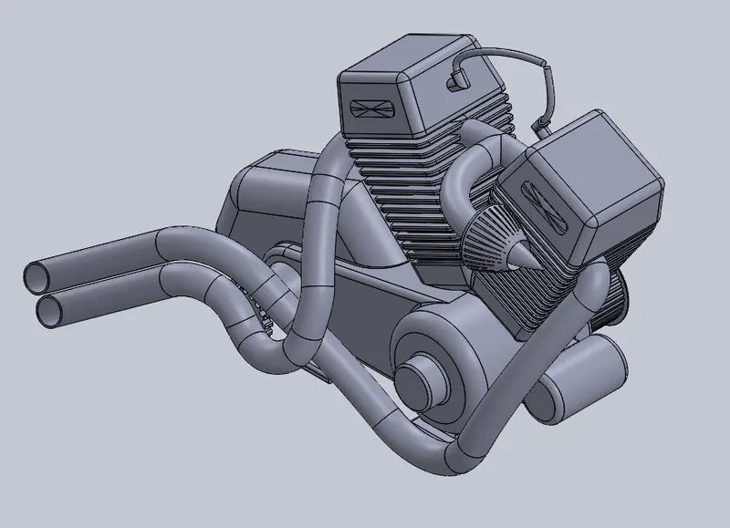
Gas Tank: This part is mainly made with splines and sweep feature. The half part of the gas tank first created and then it is then mirrored about the plane. The two separated parts were made single part by using knit feature. The gas tank covers the oil tank and engine, and also it acts shield to prevent the heat from the engine. The seat was modelled on the top of the gas tank. The fillets were added to the edges of the gas tank. At the last shell feature were added to make it hollow from inside.
Features used to create the Gas tank:
- Blueprint sketch
- Spline
- Surface sweep
- Surface trim
- Surface boundary
- Surface loft
- Curve
- Mirror
- Surface knit
- Surface extrudes
- Fillet
- Extrude cut
- Shell
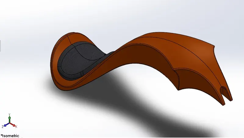
Assembly of the Chopper: All the parts that are modelled in the part module are imported to assemble them. In assembly mating is performed as per requirement(to locate and relate the parts with one another). Chassis is main component which is inserted first and therefor fixed automatically by solidworks. The other components were inserted one by one and by using planes for reference and giving the mate feature to assemble with the main frame. We can modified the parts during assembly to avoid overlapping.
Decals: A decal is a picture, image, pattern, or design that’s printed on metal body. We have added decals on Rear fender, Gas tank and Oil tank of chopper. We use label on rear fender and oil tank, and projection on gas tank. It gives nice look to the chopper.
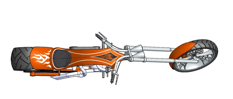
TOP VIEW: VIEW:
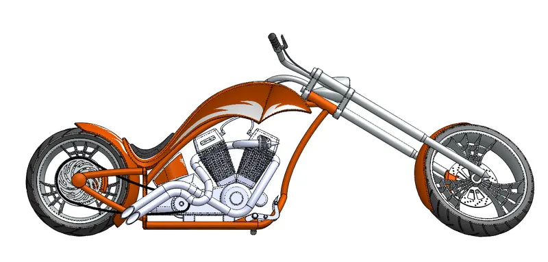
FRONT VIEW:
ISOMETRIC VIEW:
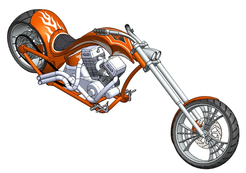
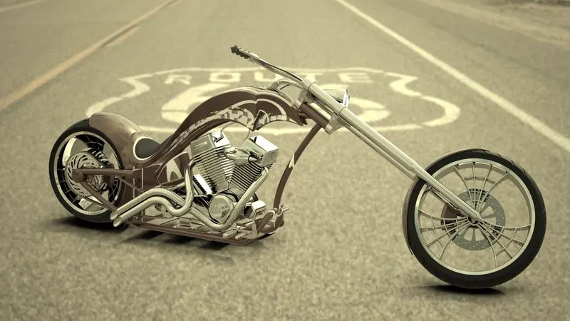
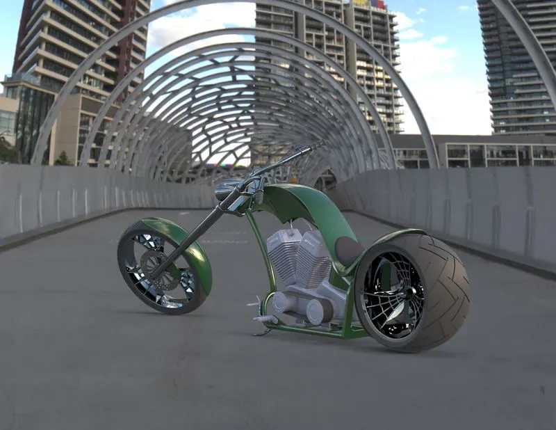
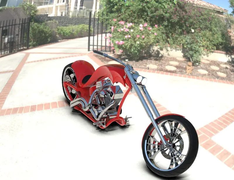
Rendering: In Computer-Aided Design (CAD) a rendering is a particular view of our assembly/body as realistic as possible.
By using PHOTOVIEW 360:
We can use camera, lighting, bloom, cartoon/counter, different background, environment and also schedule renders by help of task scheduler tool. We can change color, brightness and gamma values after rendering also, and also can compare previous render image with current render image.
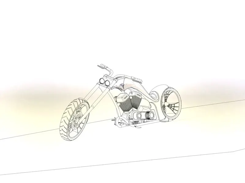
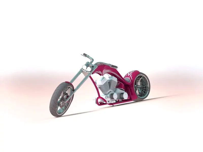
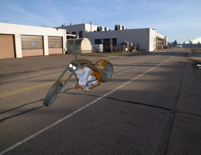
This rendering is done in the SOLIDWORK Visualize software:
we can add multiple camera views to the model, we can set various angles, direction, and can set appropriate distance to get the perfect camera view. In rendering we change color of chopper and make it pope by changing face color, flank color, background images, brightness, Gamma, rotation. Including the resolution and setting number of passes and type of render and CPU, GPU, Hybrid settings to reduce the rendering time. Here we get more realistic visual’s of chopper Bike.
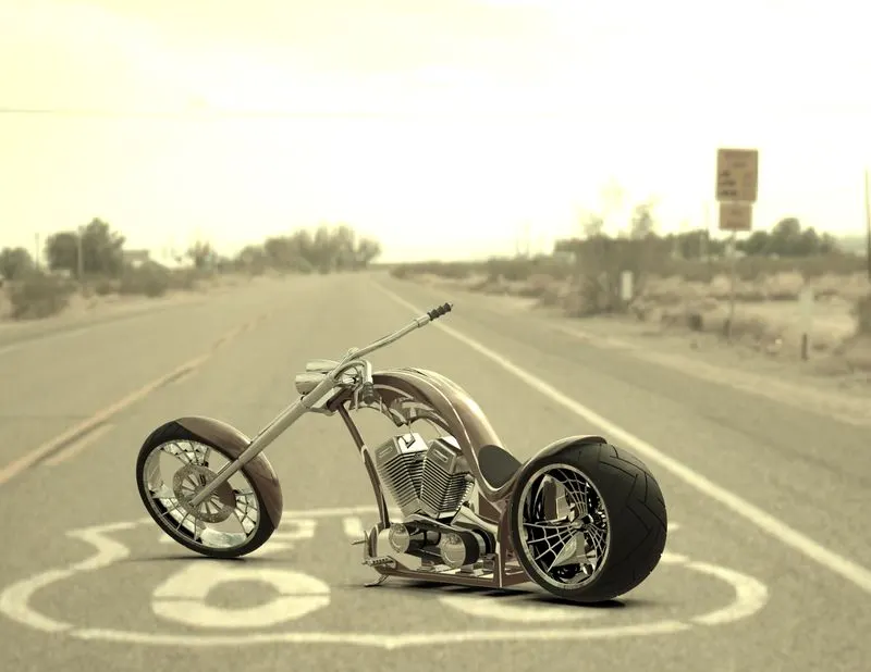

CONCLUSION:
Here we have learned to design and assemble the chopper bike and render it. Rendering helps to make our design pop and also lets us know how over design looks in the real environment.