Door Arm Rest Week 8 Challenge
REPORT - DESIGN & DRAFT ANALYSIS OF DOOR ARM REST
OBJECTIVE-creation of door arm rest of side door of thickness of 2.5 mm with help of Class A-surface along with reference of tooling axis and anylise it with draft analysis.
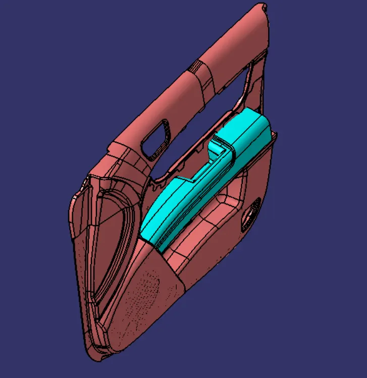
procedure to design and draft analysis-
- CREATE TOOING AXIS-In this step we havve to build the tooling axis as well as side core tooling axis.
- DESIGN OF DOOR ARM REST- TO design door arm rest we have gone to various steps like creation of class A -surface,Class B,Class C respectively.
- PREPARE DRAFT ANALYSIS REPORT- The draft report help to understand the easy disassemble of core and cavity.
PROCEDURE TO TOOLING AXIS-
1.TOOLING AXIS-
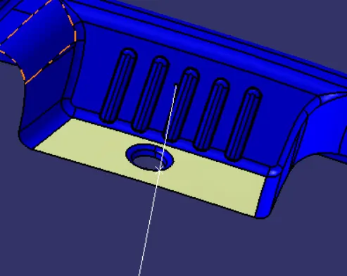
A) Main Tooling axis- mostly in mould design the by using main tooling axis we deside the location of core and cavity and part should be created along the tooling axis
- STEP 1- Extacting the base surface from class A-surface.
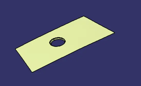
2.STEP 2- Creating point on the surface and from that point draw the line normal to the surface which ensure the main tooling axis.
FEATURE TREE CHART-
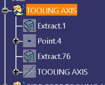
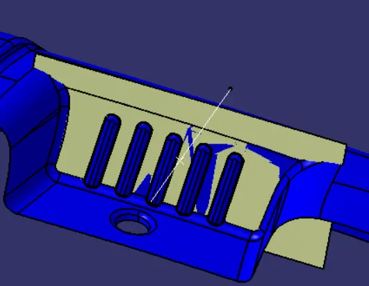
B) SIDE CORE TOOLING AXIS-Main purpose of side rooling axis to create side undercut or ribs that are difficult to obtain from main tooling axis during mould disassemble.
1.STEP 1- Extract the surface mostly which normal plane surface and will give tooling axis without any difficulty.
2.STEP 2- draw the normal line passing through the point which is lie on extracted surface.This normal line mainly calling as Side core toolin axis.
2.PROCEDURE TO DESIGN OF DOOR ARM REST-
Step 1- Extact the base surface from class A and offset it by 2.5 mm downword.
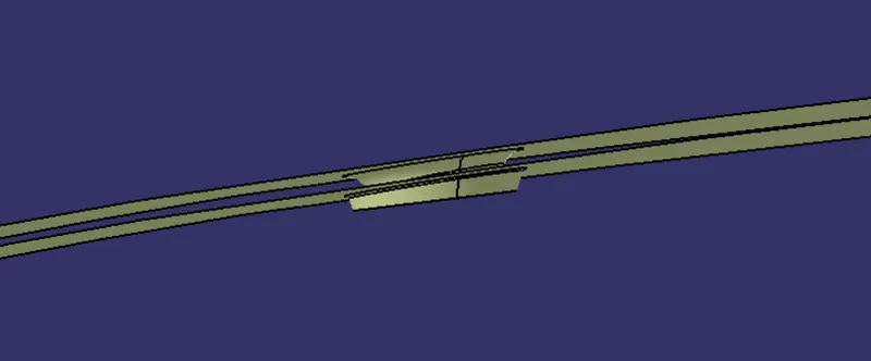
STEP 2- Extract the side wall surface from Class A surface and by offset eith 2.5 mm outward direction.
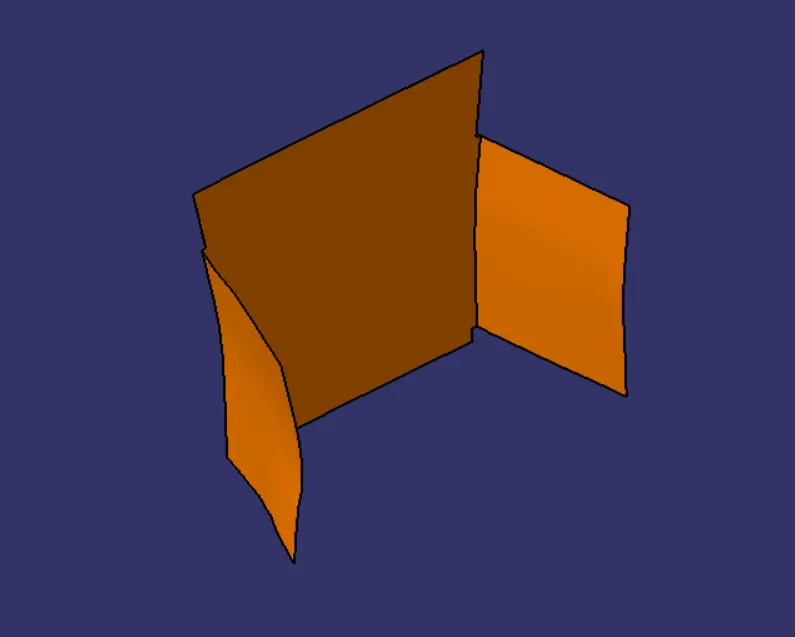
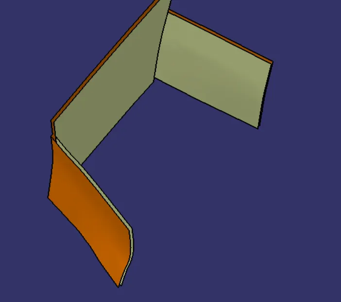
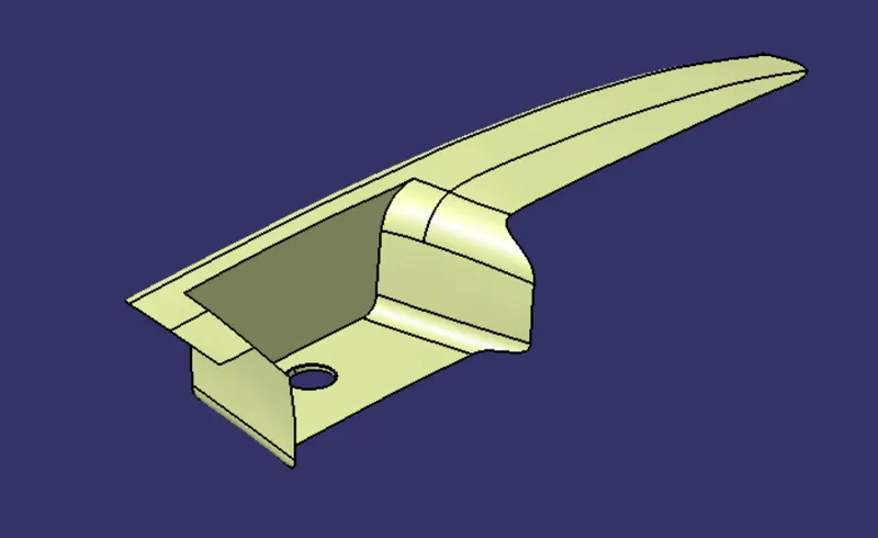
STEP 3- LOWER HALF BODY-
- Extract the upper rest surface of class A and join it with side wall surfaces.
- Trim the JOIN 1 and Base surface to get the lower half.
- create the fillets at the meeting edges with reuirement.
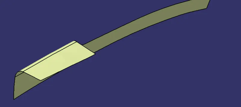
STEP 4- UPPER HALF BODY-
- EXtracting the back surface og Class A- surface along with upper rest surface.
- use the various operation tools like offset, trim,extrapolate etc..
- make the fillet on corner edges.
STEP 5- creating connecting surface to both lower and upper half body surface
A) draw the sketch on filleted surface of class A-surface
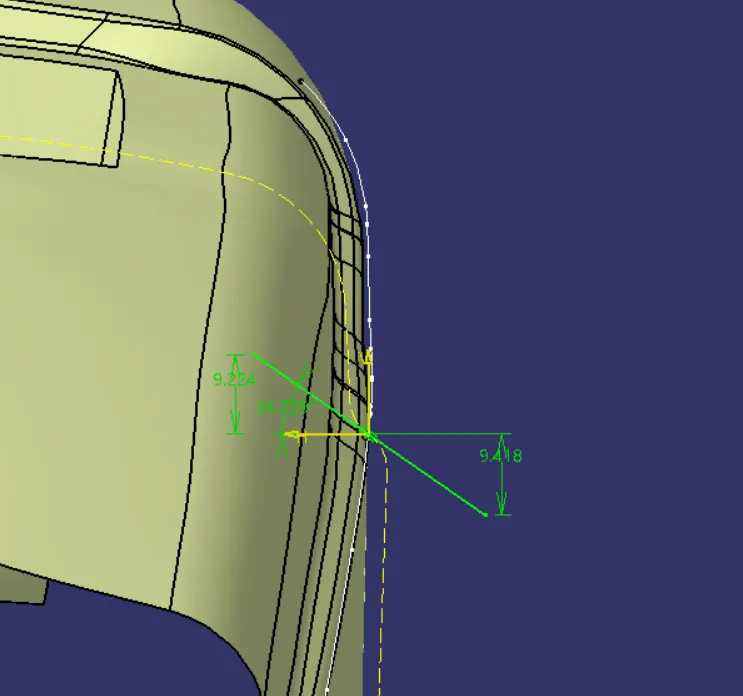
B) sweep the sketch along with the guide curve.
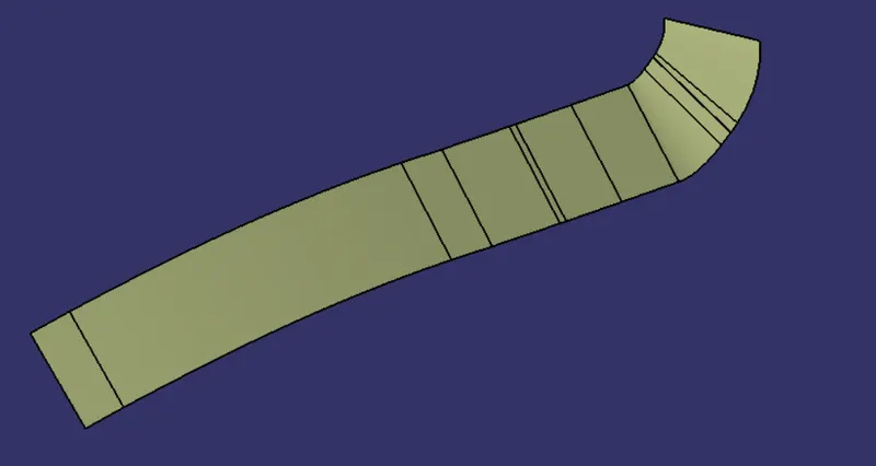
C)connect the sweep surface with parting surface of lower and upper body surface.
- first split the parting surface with sutaible distance by crating spliting line on parting surface.
- connect the edges of both sweep as well as parting surface by using BLEND SURFACE feature.
- At last joint the surface to make one single sweep connector surface part.
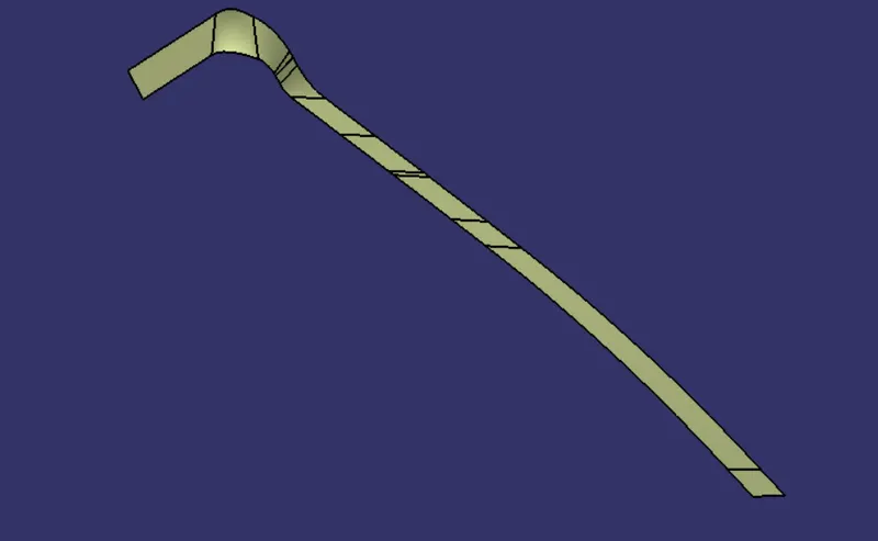
D) connecting sweep surface to lower body surface-
- extapolate the parting surface
- Trim the parting surface and sweep surface
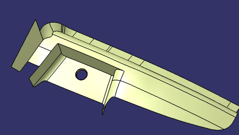
E) connecting lower body to upper body surface with help of sweep joint-
- Trim the lower sweep joint with upper body surface part
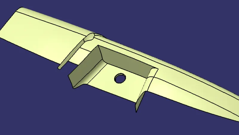
F)Creation of Class B-surface-
- For final B surface apply the fillets on sharper edges with respective fillet values.
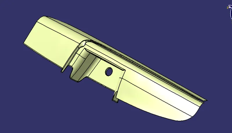
STEP 6- CREATION OF CLASS C-SURFACE
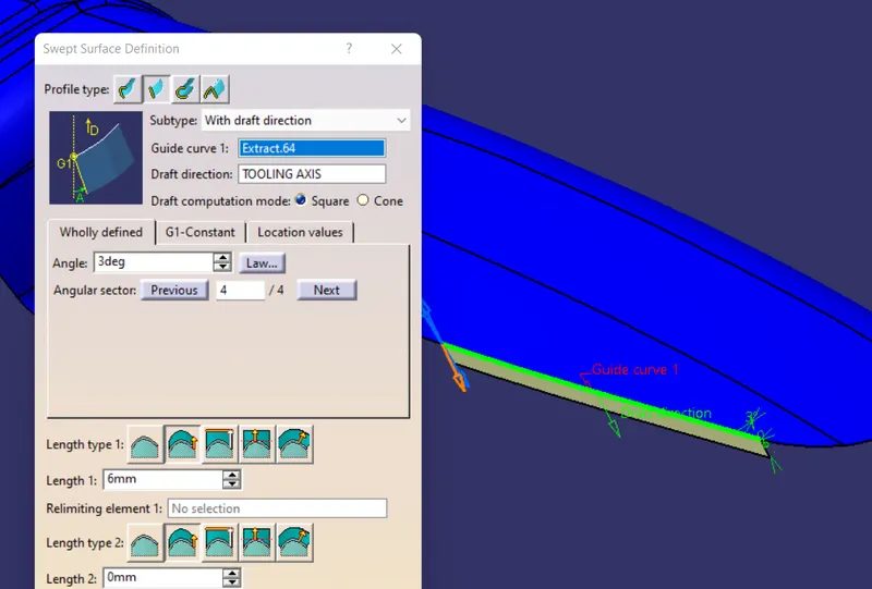
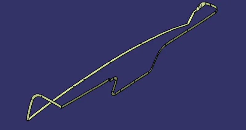
- To create the Class C-surface sweep the surface edges of Class A-surface .
- The sweep direction must be along with main tooling axis with sutaible draft angle.
- The draft angle should be 3 degree.
- Apply the multisection operation to joint two sweep surface at sharper edges.
STEP 7-JOIN THE CLASS A-SURFACE AND CLASS -C SURFACE
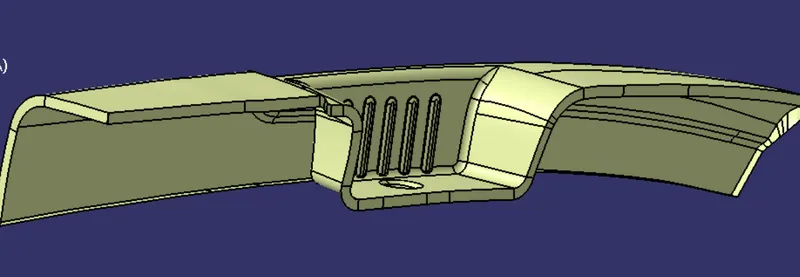
STEP 8-Creation Close surface
A) Trim the Class A & C surface joint with Class B surface-
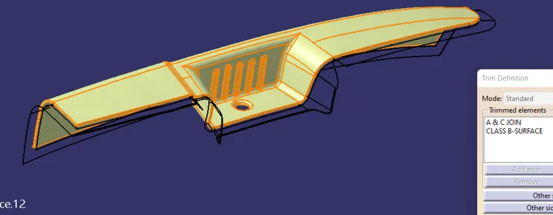
B) Close surface- Close surface means connecting the surfaces like Class A,B&C with sutaible thickness.The close surface is internaly hollow portion.
- Close surface is used to create solid body.
- Close surface must be boundaryless.means there is no any boundary present on close surface.Because it wiil interupt to solid body.
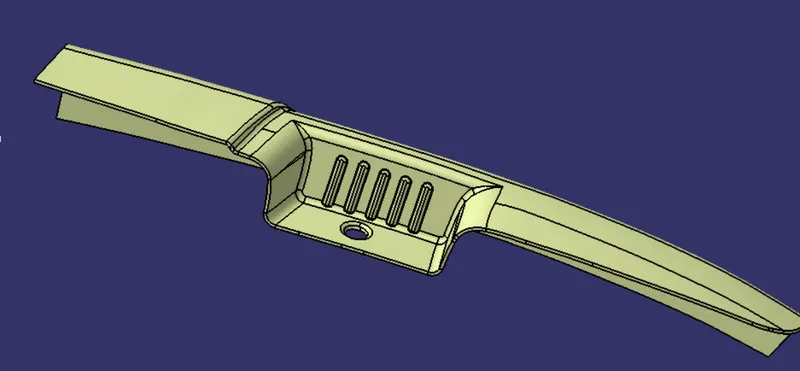
STEP-9- Conversion of close surface body to solid body
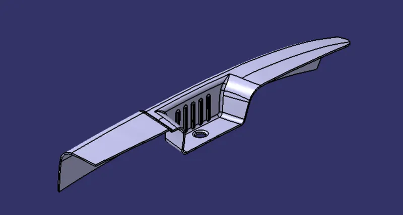
3. PROCEDURE TO DRAFT ANALYSIS REPORT-
*Procedure to create Draft Analysis-
1.Open the part file in Catia workbench.
2.Apply the material for part.For that go to view feature>Render style>Customize view parameter.
3.For draft analysis we have to select Insert>Analysis>Feature draft Analysis.Then there will be opening the Draft analysis dialogue box with showing icons like mode, display and direction.
4.Move the compass towards the tooling axis and coinside it with tooling axis.If you want to fix the compass then click on lock icon .
To start the analysis-
1.Select the surface of Part that we want to analysis.
2. click on draft analysis icon .
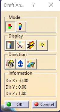
3.MODE OPTION-
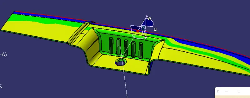
In dialoue box showing mode option with quick & full analysis mode.In that mode feature we can understand the different angle range value in colour format which indicate part is in correct drafft mode or not.
The default mode is the quick mode. It simplifies the analysis in that it displays only three color ranges.
* QUICK MODE-
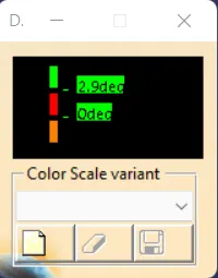
*FULL MODE-
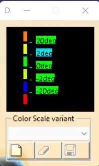
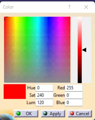
* Doble click on color range which display in dialogue box and we can change the color range.
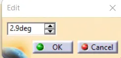
*Also by double click on the angle value ,we can modify it.
*The colour mode and respective Draft angle value is set in mode dialogue box.
- When the Draft angle value of the surface is equal or smaller than graduated (fixed in dialogue box) value,the colour will be applied as per graduated value to the surface.
- When the Draft angle value of the surface is greater than greatest value of graduated,the colour of graduated value is applied.
4.DISPLAY OPTION-
- color scale-This dialog box only appears in edition mode.Means we have to activate Full mode or Quick mode analysis.
- Angle Pointer-activate the pointer and move it over the surface which showing various draft value at different locations.
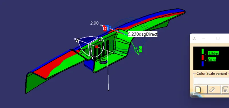
Arrows are displayed under the pointer, identifying the normal to the surface at the pointer location (green arrow), the draft direction (red arrow), and the tangent (blue arrow). As you move the pointer over the surface, the display is dynamically updated. Furthermore, circles are displayed indicating the plane tangent to the surface at this point.
- No highlighted & Representation icon-This feature gives option like on/ off the highligh portion of part.As it enable ,it will show all edges in colour (highlight) format.
- LIGHT EFFECT-This feature helps to understand the visualisation effect of part under light effect.This light effect will affect the visualiser's eye.
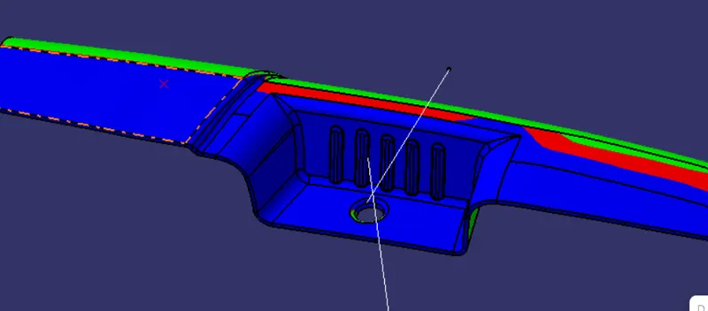
- Inverse direction- It allows to change the direction of draft angle of selected part.As the we click on reverse direction then there is changing gaduated colour effect ( in negative).It shows the BLUE colour.
5. DIRECTION -
- LOCKED DIRECTION- In that we can lock or unlock the draft angle direction,a plane,a Face which is used in current analysis.
- COMPASS- It is used to define the new or current draft direction.To set the compass direction on Tooling Axis,we have to move or pull the compass origin and coinside with tooling axis.
6.Once we have finished the analysing the surface by applying propper elements CLICK on OK icon in DRAFT ANALYSIS DIALOGUE BOX.The analysis is added to tree chart of part.
IN this way we can genrate the report for Draft Analysis for a given part by using Feature Draft Analysis.
The images of Draft Analysis are as follow-
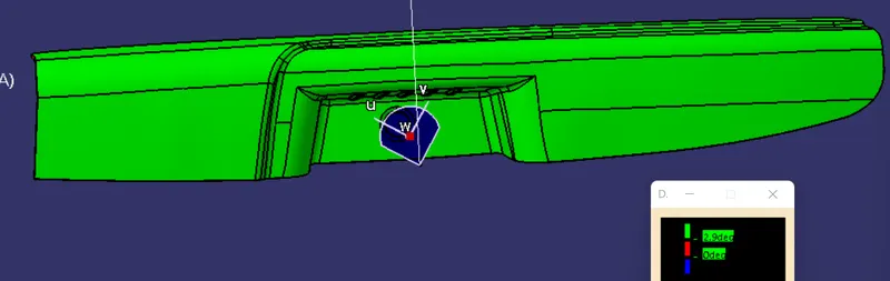
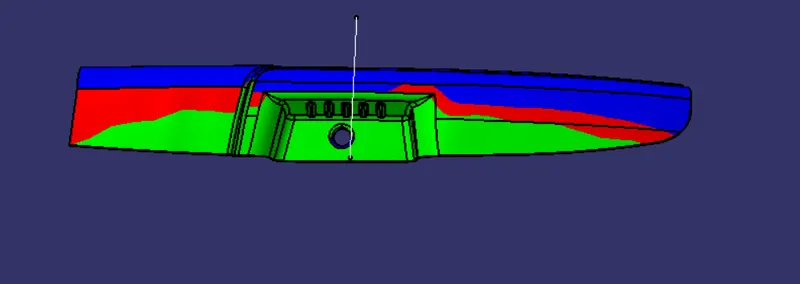
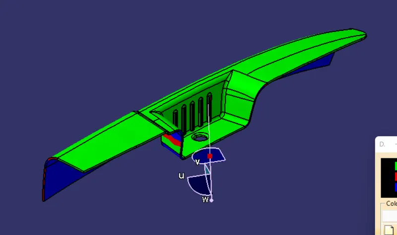
1.Quick Analysis mode- with color scale variant & Complete draft Analysis
A) main tooling axis-&
B)Side core tooling axis-
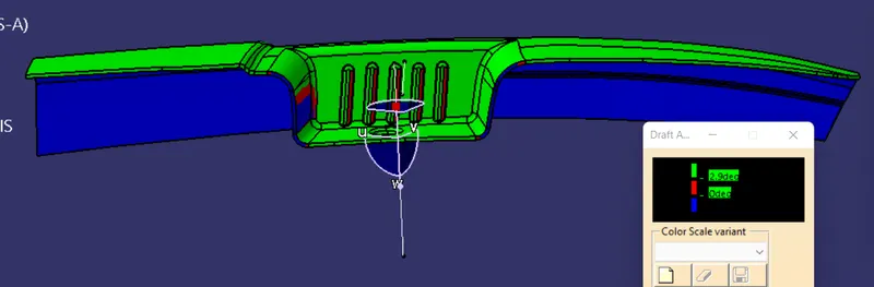
*FRONT VIEW-
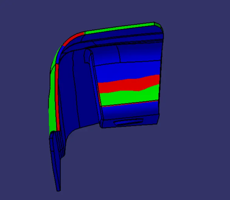
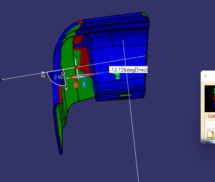
SIDE VIEW-
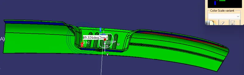
TOP VIEW-
ISOMETRIC VIEW
2.Full Analysis mode- with color scale variant & Complete draft Analysis
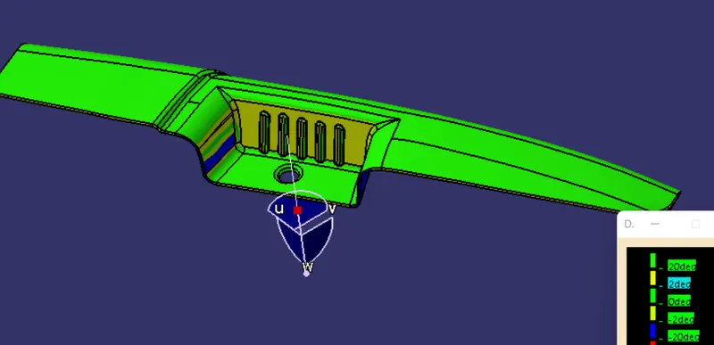
3.Inverse Draft Direction Analysis-
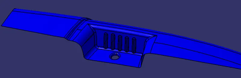
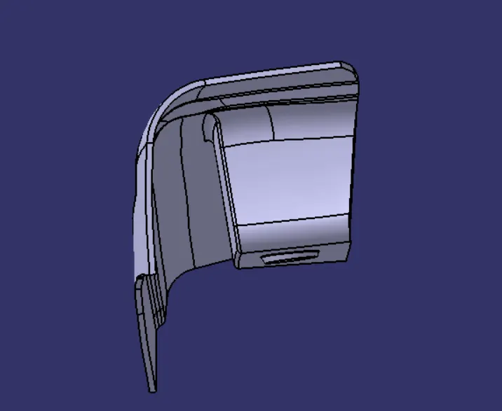
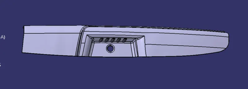
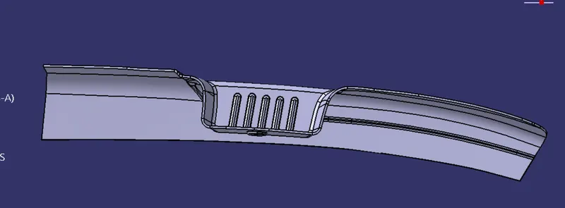
*Different orientation views of Door Arm Rest with Class A,B &class C-surfaces-
**RESULT OF ANALYSIS-
1.GREEN COLOR- Here Green color shows that the draft analysis is positive and there is no error in model.The angle more than 3 degree is considered as positive draft angle.It indicate that core will diassemble easily without wear and tear
2.Blue & Red Color- Red and Blue color shows negative draft angle.It appears below the part upper surface that is not affect on core during ejection.
*CONCLUSION-
In Draft analysis we can learn about provided draft angle is correct or not.Draft angle decide the part ejection from mold with smoothly.Draft analysis shows part whethere positive or negative draft angle.
Also we can learn how to generate Tooling axis with the help of intersecting the surface along with normal to surface and finally we create main tooling axis.
- learn about to create side core tooling axis.
- learn to uses Trim,Extrapolate,sweep,untrim,offset,join,multisection operations.
- learn to draft analysis and change the error.
- learn to split and blend the surfaces
- learn to extract tangential boundary.
- learn to multiple extract curve and smoothing curve.