Photo Realistic Rendering
AIM:- To write reports on assembly of chopper model.
“MODELING OF AMERICAN CHOPPER ON SOLIDWORKS”
INTRODUCTION
In this project we learn how to design assembly of chopper, starting from its individual parts with the very popular software called as SOLIDWORKS. In this we learn from the basics like how to use shortcuts, introduction to user interface, how to use commands, how to draw to sketch, how to customize the tools on menu bar and then we start to draw sketches. Further we used blueprint and draw sketches accordingly.
After designing on all parts, we do assembly of American chopper. In order to appear chopper more realistic we add decals, lights, camera and do rendering by using SOLIDWORKS Visualization.
The Parts which we design in Chopper are as follows: -
- Chain and Transmission belt
- Kickstand and pedal
- Oil tank
- Front and Rear Fender
- Front Fork
- Front and Rear Wheel
- Engine with Exhaust system
- Chassis
Objective: -
- To understand the basics of Solidworks like its user interface and shortcuts keys.
- To understand how to use commands, how to define sketch and how to draw sketches by using each entity like circle, rectangle, etc.
- To draw sketches on blueprint.
- Assembly of chopper in solidworks.
- To understand rendering with the help of Solidworks Visualization.
What is Design Approach?
There are two types of approach in design given below: -
- Bottom-up type approach
- Top-down approach
- Bottom-up approach: - Bottom-up design is the traditional method where we first design and model parts, and then we do assemble and then give mates to meet their specific position. In this project we used Bottom-up approach.
- Top-down approach: - In Top-down design, in assembly only shapes, size and parts can be design.
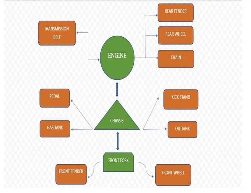
The Features in solidworks is the key to design an entire model.
There are number of features but we will see how many of we used during our modelling in solidworks.
- Extrude Boss
- Extrude cut
- Revolve Boss
- Fillet
- Shell
- Linear pattern
- Mirror
- Reference Geometry
- Split Mate
1) Extrude Boss: - This feature requires a sketch to do extrude, the sketch should be fully defined. Once the sketch is created exit from sketch go to command manager and select extrude boss, one box will appear, enter the value as per our requirement it will a material to existing sketch.
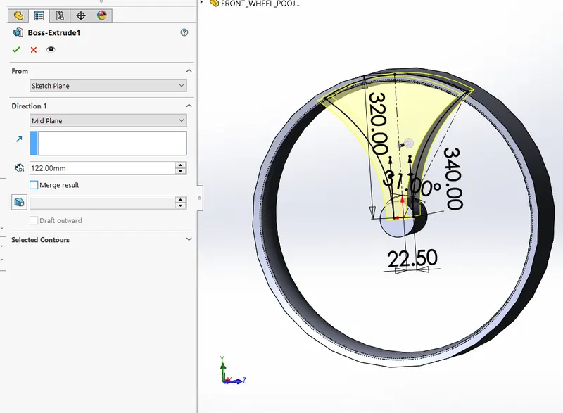
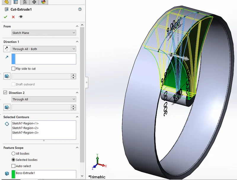
2)Extrude Cut: - To do extrude cut we need a plane or planar face or an edge on which to create a sketch for the entity. First give the relations to sketch or dimensions then exit from the sketch and then click on extrude cut command on feature tab, select the direction, rotate the body to see the preview of cut on solid body.
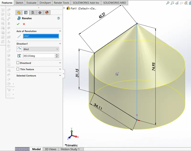
3) Revolve Boss: - In the revolved boss base, sketch need an axis. Pick the axis or an edge we wish to use for the revolve by specifying direction and angle.
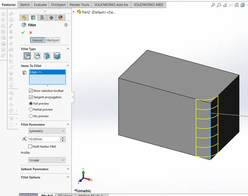
4)Fillet: -The main purpose of Fillet in any drawing is to remove sharp corners on those selected edges, by removing material. The edges may be internal or external. To achieve the rounded shape, we need to click fillet command on the feature tab then property manager will appear to select edges, faces or profile which is to be fillet. There are various types of Fillets, we use as per drawing or model convenience.
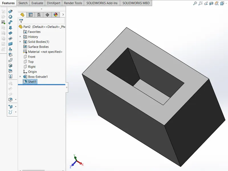
5)Shell: - The inside of drawing needs to be hollowed. It shows the clear idea of inside geometry that how it will appear. To use shell command is very easy. The shell command allows us to define thickness and becomes hollow by selecting the face.
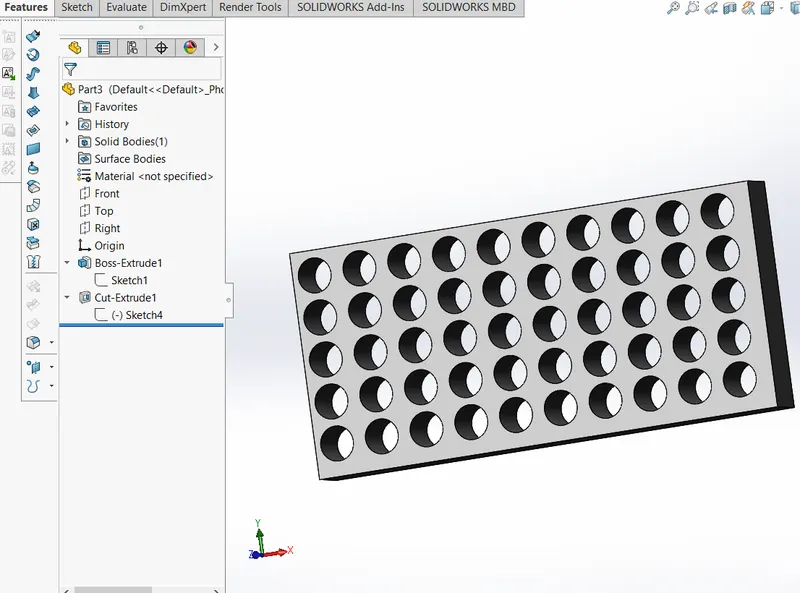
6)Linear Pattern: - It is used when the sketch is open, we can give nu of pattern in sequence whose difference like spacing, angles, and path is same at all.
There are two types of pattern linear and circular.
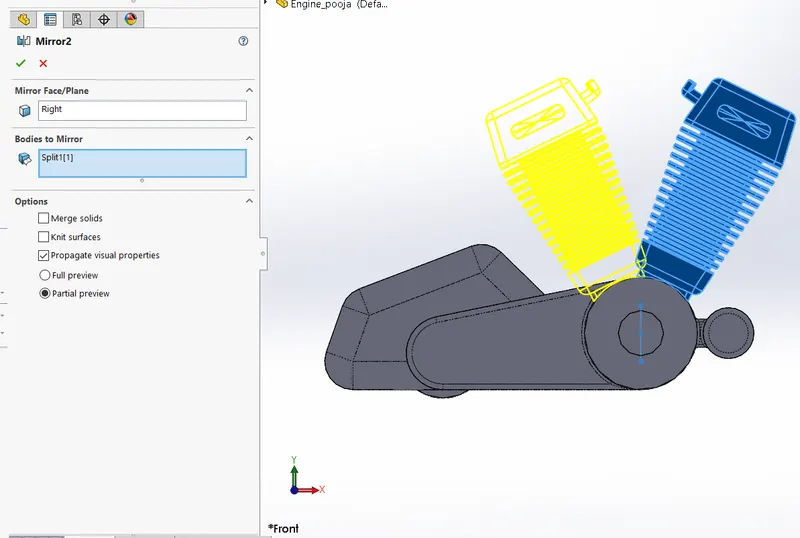
7) Mirror: - In this feature get an exact replica of solid part. In this we need to click a model or plane about which to mirror the part. From feature select the mirror then select body which is to be mirror, select an axis or plane and the exact copy will get called mirror.
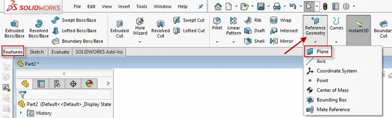
8) Reference Geometry: - Reference geometry includes planes, axes, co-ordinate system and points. We can use reference geometry in various features according to conditions. Reference geometry command lives on the feature toolbar but we can also access it, insert>Reference Geometry.
There are two types:-
- Reference Plane
- Reference Axis
9) Mate: - It is the concrete feature in solidworks. As the name implies, it is a mate between two concentric features.
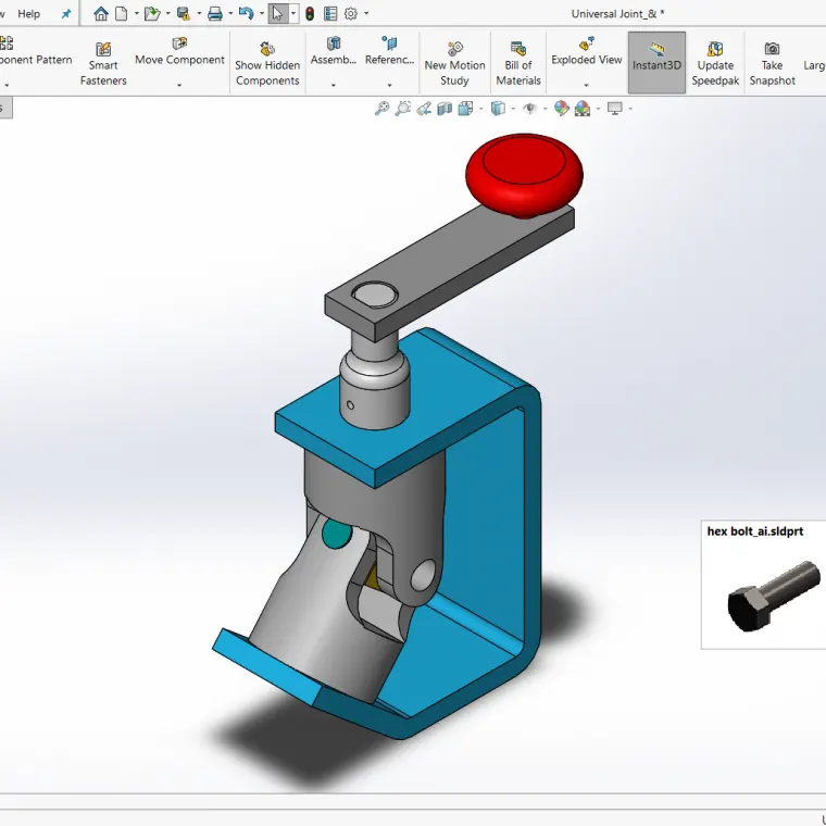
When we select mate it defines according to its relation like Tangent, concentric, coincident and angular and fix according to assembly behavior.
- Tangent mate: - A tangent mate will keep two faces, edges or plane touching at all time.
- Coincident Mate: - As name sounds, is a mate between two features that we want to coincide with each other. Generally, we use it for making two planes parallel and coincident.
- Concentric Mate: - In concentric mate circular faces is to selected one can move with other along common axis.
- Angular Mate: - This makes angular relation between the surface having some angle and flat surface.
This all above points or explanation is regarding how Features work in solidworks.
Now let's move on to application parts, which we learn on the basis of this features and drawn our model successfully.
We model our Chopper step by step, will discuss below: -
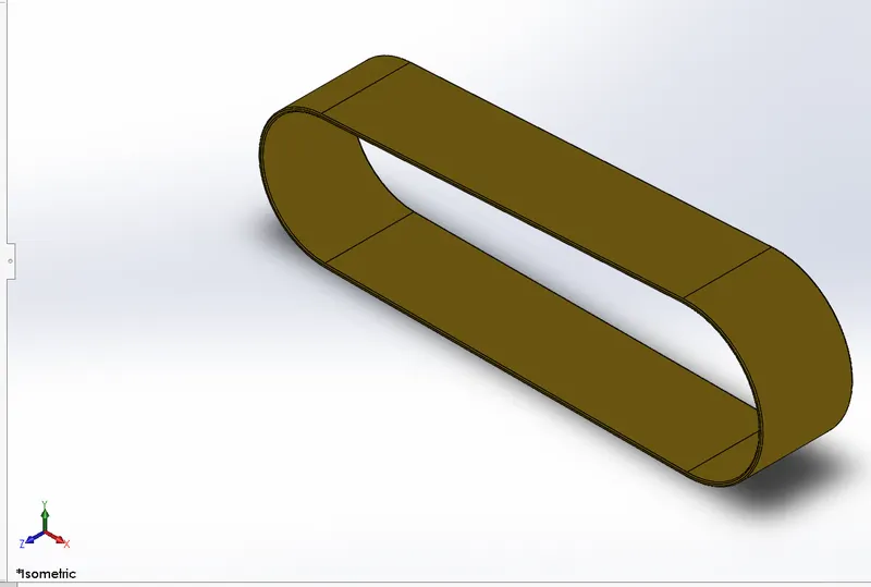
TRANSMISSION BELT: - The main use of Transmission belt is to transmit the power between two shafts. This belt is created in front plane having some thickness and extrude to convert in 3D and used fillet. In order to appear more realistic, we have given appearance as a matte Rubber.
Features used to create the belt:
- Sketch
- Extrude
- Fillet
- Appearance
KICKSTAND: - Kickstand is used to stand in little vertical direction when our bike or motorcycle is in stationary. First, we have created a sketch by giving proper dimensions then used loft Feature to create a stand base by ellipse and also used dome feature to convert flat face into round face at top and bottom. Then Cut extrude is given so as to mate between stand and chassis, and boss extrude is given at top side of sketch and finally fillet to look good.
Features used in Kickstand:
- Sketch
- Ellipse
- Loft
- Dome
- Extrude cut
- Boss extrude
- Split Fillet
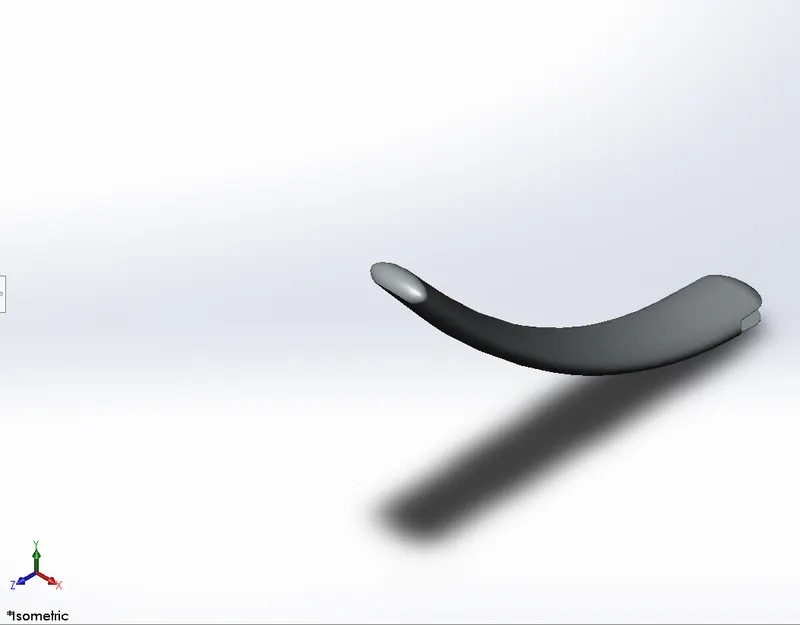
FRONT FENDER: - This part creates in front plane by using 3-point arc and revolve into specific angle. Then create another two sketch to split and remove a part to get required design and then applied fillet to edges.
Features used in Front Fender:
- Sketch
- 3-point arc
- Revolve
- Split
- Fillet
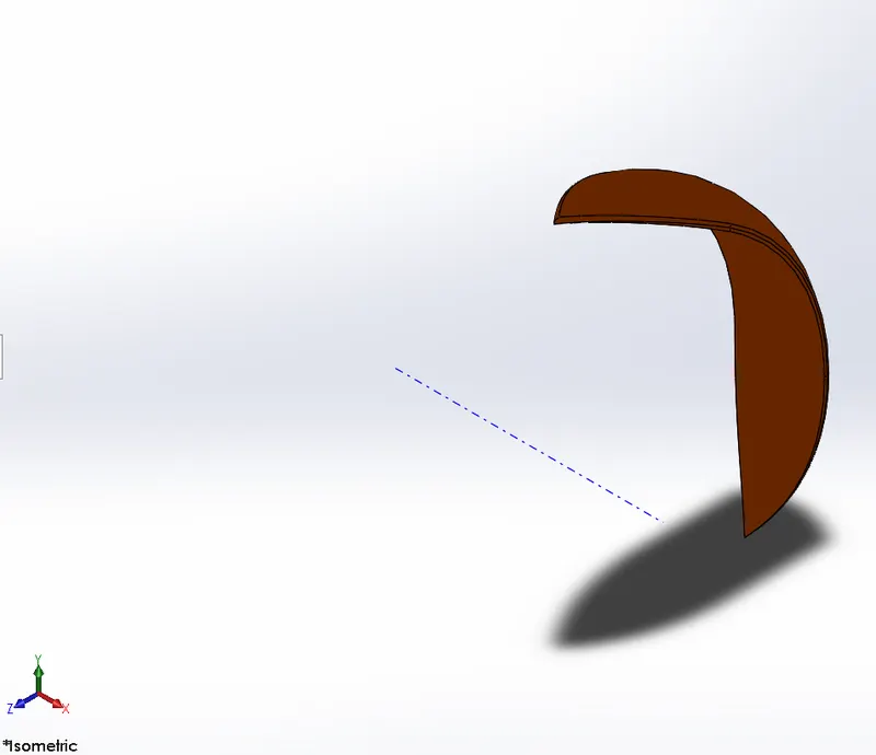
REAR FENDER: - A sketch create in front plane by using 3 point arc and offset to get thickness of fender and revolve it particular angle and create another sketch to split and remove part then fillet the edges and then shell.
Appearance given is sienna.
Feature used in are:
- Sketch
- 3-point arc
- Revolve
- spline
- Fillet
- Shell
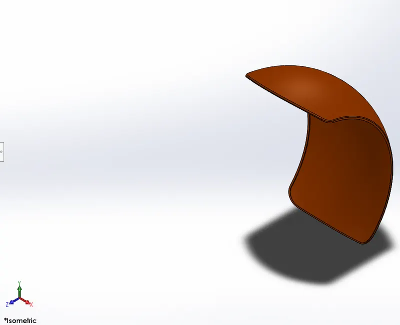
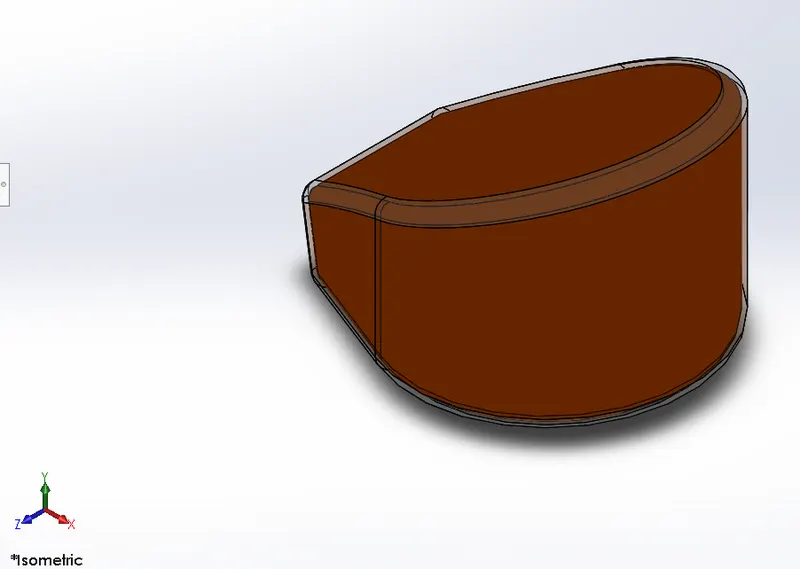
OIL TANK :- It is used to store the oil for better performance and efficiency. This part model creates by combination of two sketches. Then we boss extrude and combine it to make one part which will look like tank, then we fillet and shell.
We used two appearances here sienna to oil tank and white paint on the edges of oil tank.
Feature used in are:
- Lines
- Boss extrudes
- Combine
- Fillet
- Shell
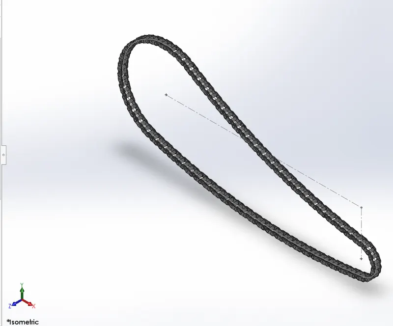
CHAIN: - It helps to transmit the power between engine to rear wheel with the help of sprocket.
In this mainly we used reference sketch in front plane. We used arcs and lines to draw sketch then we created a blocks and pins and extrude it. Then we used curve pattern along the path and given nu as per calculation. As the front side chain is pattern, we used mirror and combine. And to look more realistic we have given chrome metal as an appearance.
Features used in are:
- Sketch
- Circles
- 3-point arc
- Slot
- Block
- Boss extrudes
- Fillet
- Curve
- pattern
- Mirror
PEDAL: - It is use to rest the foot in order to give comfort to rider. Like every sketch, here also we created a sketch by giving specified relation and define them. The appearance given to pedal is chrome metal.
Features used in are:
- Sketch
- Circles
- Boss extrudes
- Fillet
- Revolve
- Dome
- Chamfer
- Linear pattern
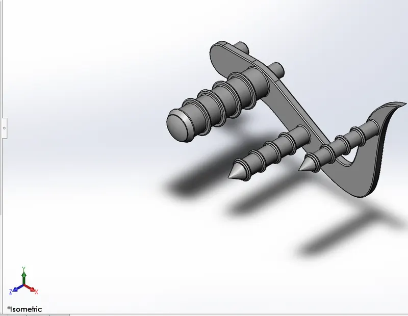
FRONT WHEEL: - The major components of wheel are Rim, Rotor, Caliper and Tire.
First Rim was created by using revolve boss. Then we sketch on face to crate rotor and caliper and then circular pattern to make holes in rotor. Chamfer and fillet are also used. Spider webbed were created using splines. Then we did pattern to the Rim. The spider web and Rim were merged. The appearance given to the tire is matte Rubber, Caliper is if sienna and Chrome metal is for Rotor and Spokes
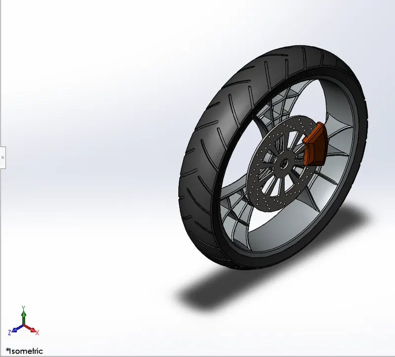
Features used in:
- Sketch
- Revolve
- Boss extrudes
- Revolve
- Cut extrude
- Circular pattern
- Mirror
- Combine
- Chamfer
- Fillet
REAR WHEEL: - The main function of Rear wheel is to push the vehicle forward, the power from the engine is delivered to the rear wheel. Rear wheel is where more shifting and breaking will happen. The whole procedure is same as front wheel.
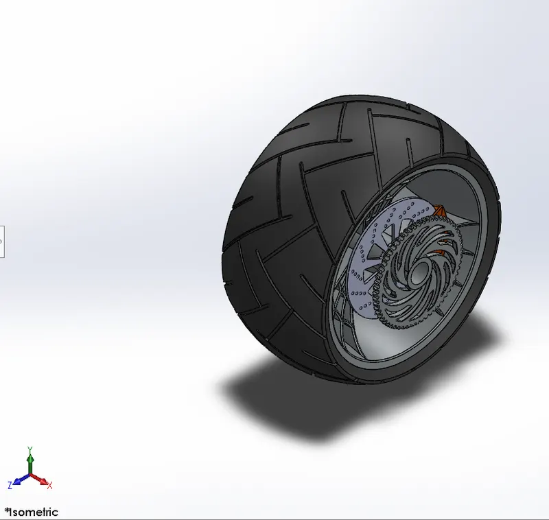
Features used in are:
- Sketch
- Revolve
- Boss extrudes
- Revolve cut
- Cut extrude
- Circular pattern
- Mirror
- Combine
- Chamfer
- Fillet
FRONT FORK: - Front fork is nothing but the large shock absorbers, it helps to balance and turn a wheel into desired direction which is held by triple clamps. First, we created a long tube then sketch on face to create clamp and projected a curve to create a handle bar then activate a swept feature and revolved a whole design and mirror it. To make a single part we combine it and given appearance.
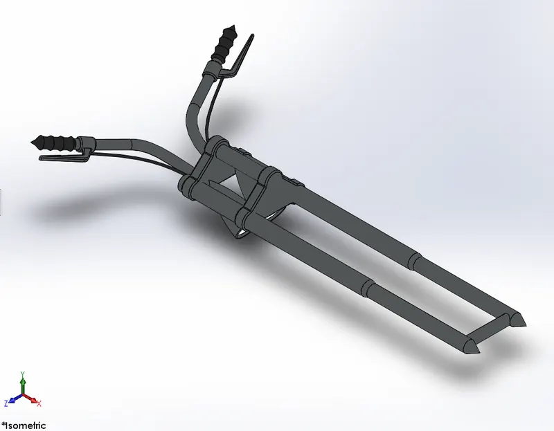
Feature used in are:
- Sketch
- Revolve
- Circles
- Fillets
- Linear pattern
- Spline Extrude cut
- Dome
- Curve
- Sweep
- Plane
- Boss extrudes
- Mirror
- Combine
CHASSIS: - It is a base for every vehicle. It is a skeleton of motorcycle because it carries every part in the vehicle. It supports system of all components and vehicle too. All the component such as suspension, wheels, fuel tank, engine kickstand gives the chassis to handle well. In this we used Blueprint to sketch.
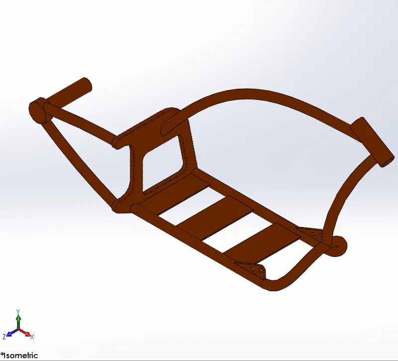
Features used in are:
- Splines
- Curves
- Mirror
- Boss extrudes
- Extrude cut
- Chamfer
- Dome
- Split
- Revolve
- Combine
ENGINE: - Engine is the main component of vehicle. An engine is a system that is design to transform mechanical energy into one type of energy. Blueprint is used in this for reference to do modeling. The engine consists of exhaust manifold, crank shaft and pulleys. We used features spline, curve, boss extrude, fillet, revolve, dome, circular pattern, cut extrude and mirror. The appearance is given as chrome metal.
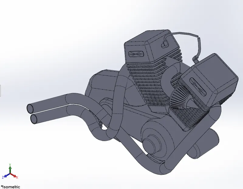
Features used in are:
- Sketch
- Convert entities
- Trim
- Revolve
- Boss extrudes
- Extrude Cut
- Offset
- Dome
- Fillet
- Projected curve
- Composite curve
- Sweep
- Linear pattern
- Mirror
- Split
GAS TANK: - A gas tank is a safe reservoir for flammable fluids. The fuel is stored and propelled into an engine. we used spline and sweep feature to make a half part then we used mirror about plane. Here we added decal on the upper surface of body to give good appearance.
Features used in are:
- Blueprint sketch
- Spline
- Surface sweep
- Surface trim
- Surface loft
- Curve
- Mirror
- Surface knit
- Fillet
- Extrude cut
- shell
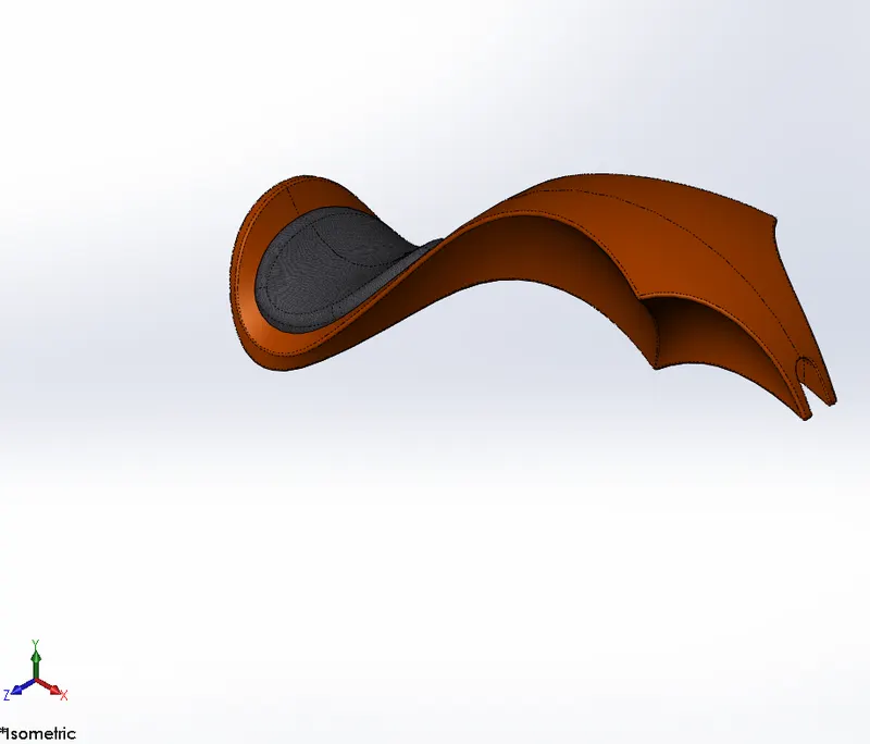
ASSEMBLY OF THE CHOPPER: - In solidworks, all the designed parts are taken into the assembly section and then started whole assembly by specifying their respective mates. Mate is the most important feature to give relation such as coincident, concentric, tangent and angular. First, we have taken chassis in account and then started giving mates to parts one by one according to their position. Some of parts needed modification in order to fix appropriately, so we modified those parts individually to avoid dislocation of another parts.
DECALS: - We can call it as a sticker which has verities of images, pictures or designs that can be printed on metal body. Here we added decal on Rear Fender, gas tank, oil tank of Chopper. This use of decal gives more realistic view to chopper.
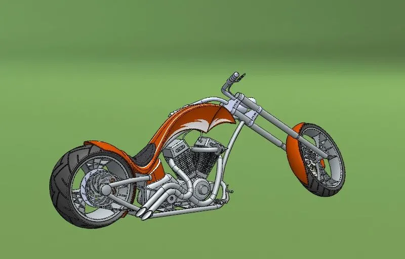
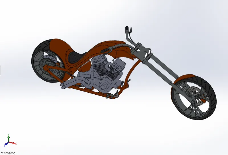
RENDERING: - Rendering is the method to view our model into realistic environment. In this, we can add cameras, lights, decals, various types of scenes, we can adjust angles. In rendering we can set different color, different background. we can give resolution as per our convenience and get exact visualization of chopper in Solidworks visualization software.
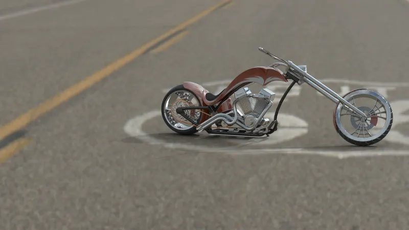
Conclusion - This way we modelled American chopper in solidworks Rendered.