Photo Realistic Rendering
MODELLING OF AMERICAN CHOPPER USING SOLIDWORKS
Objective :
The main objective of this project is to design the individual components of the American Chopper using the SolidWorks software and to assemble them. After completing the assembly of the Chopper bike to render it with SolidWorks PhotoView 360 (Render tool) to create a photorealistic view of the bike.
The main Objectives of this project is :-
- To model the individual components of the Chopper bike
- To assemble the individual parts into American Chopper bike
- To render the Chopper bike with decals and camera views.
Introduction :
SolidWorks :-
SolidWorks is a 3D CAD design software, analysis software and product data management software which is developed by the Dassault systems. At the initial stage, the software is used for planning, feasibility assessment, prototyping and project management. The software is then used for design and building of mechanical, electrical and software elements.
American Chopper Bike :-
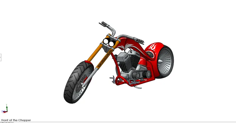
A Chopper bike is a custom motorcycle which emerged in California in the late 1950s. The chopper is perhaps the most extreme of all custom styles, often using radically modified steering angles and lengthened forks for a stretched out appearance.
Design methodology :
The main steps involved in design methodology are.
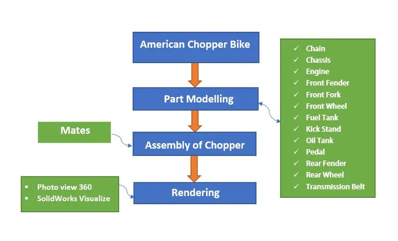
Description of Tools and Features :
Sketch Tools :-
Sketch tools are used to create the 2D representation of the model. The status of the sketch is identified by the color of the sketch profile. If it is black color, it is fully defined, Blue means under defined and red color indicates over defined. The various types of the sketch tools used in this chopper bike design are.
1. Line
2. Circle
3. Arc
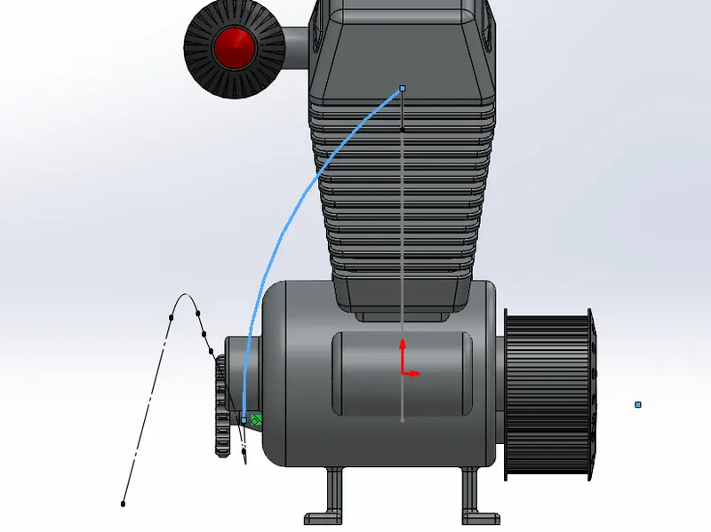
4. Spline - It is used to create the complex curves.
5. Rectangle
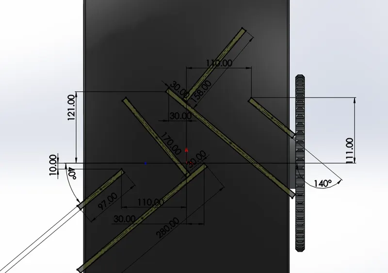
6. Fillet - Creates the rounded shapes at the corners.
7. Convert entities - Allows users to make a copied projection of a given sketch, face or set of edges onto the active sketch plane.
8. Intersection curves - Create the copied sketch of the curved faces on the active sketch plane.
9. Offset entities - An profile is offset to the specified distance.
10. Trim entities and extend entities - Trim is used to remove the unwanted end portions of the sketch. Extend is used the extend the edge of the curve to the next meeting point.
11. Smart dimensioning - Used to dimension the sketch
12. Mirror entities - Mirrors the sketch about a selected reference plane or axis.
13. Dynamic mirror sketch entities - Select the dynamic mirror feature to mirror a pre-existing sketch. First select line, center line and linear model edge about which to mirror, and then create a sketch to mirror.
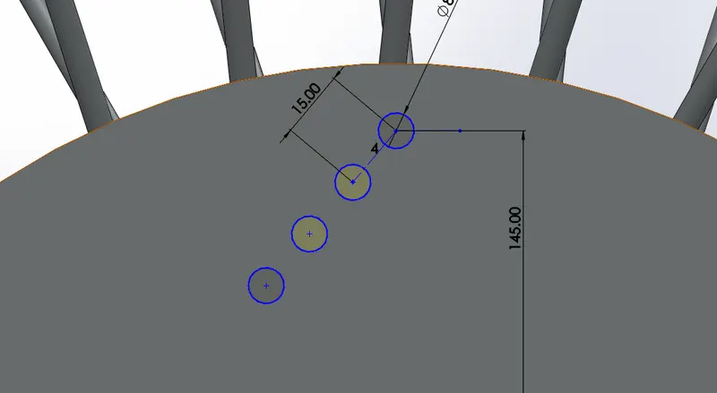
14. Linear and Circular sketch pattern - Create the copied versions of selected sketch profiles in a linear manner or in a circular manner.
15. Ellipse
16. Geometric relations - These are the most powerful features in SolidWorks sketch environment. Various types of relations such as concentric, mid-point, coincident, Tangent, Vertical and horizontal are used.
3D modelling tools :-
1. Extruded Boss - It is used to extrude the solid body from the sketch.
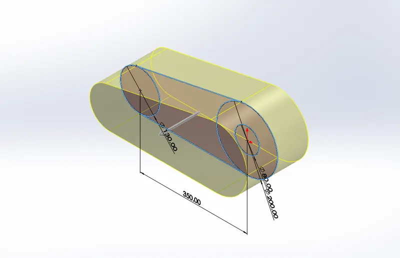
2. Extruded cut - It is used to cut the solid shapes in the extruded body.
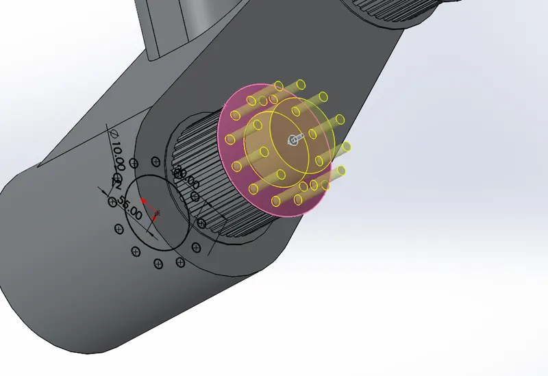
3. Revolved boss - It creates the solid body around the axis, means cylindrical or circular bodies.
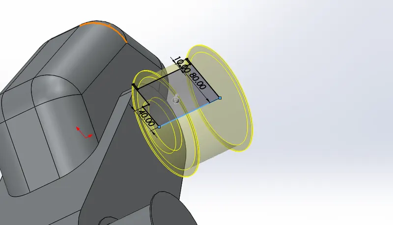
4. Revolved cut - It is used to cut the body along the circular path about an axis.
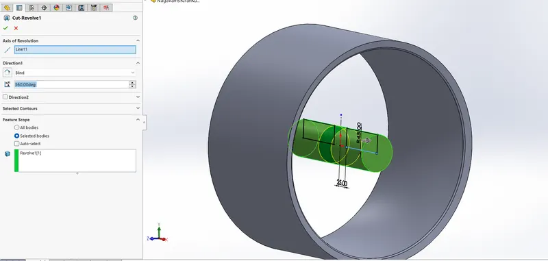
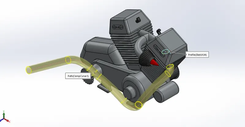
5. Swept boss - An sketch profile is swept along the pre-drawn path to create the solid body.
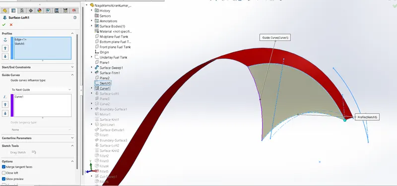
6. Lofted boss (Surface loft) - An lofted boss is created between two bounded profiles, which is followed by the guide curves.
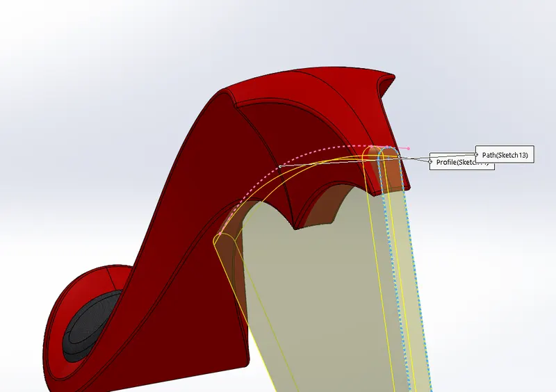
7. Swept cut - An cut portion is created along the path.
8. Fillet and Chamfer - Smoothening the corners of the sharp objects by circular or edge feature.
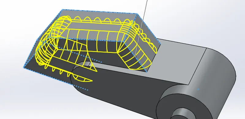

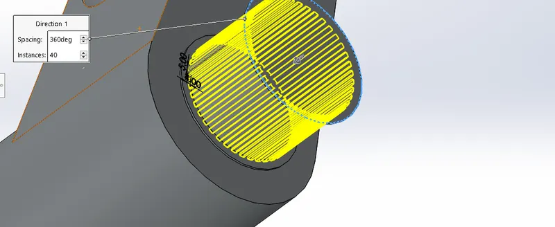
9. Linear, Circular and Curve driven pattern - An solid body is patterned along the linear or circular or curve.
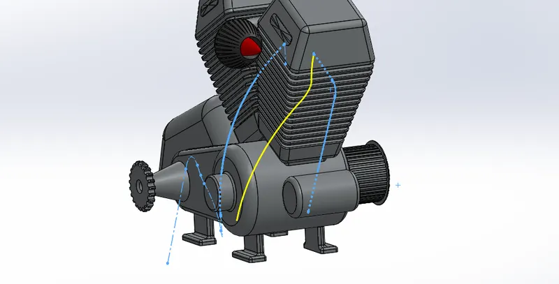
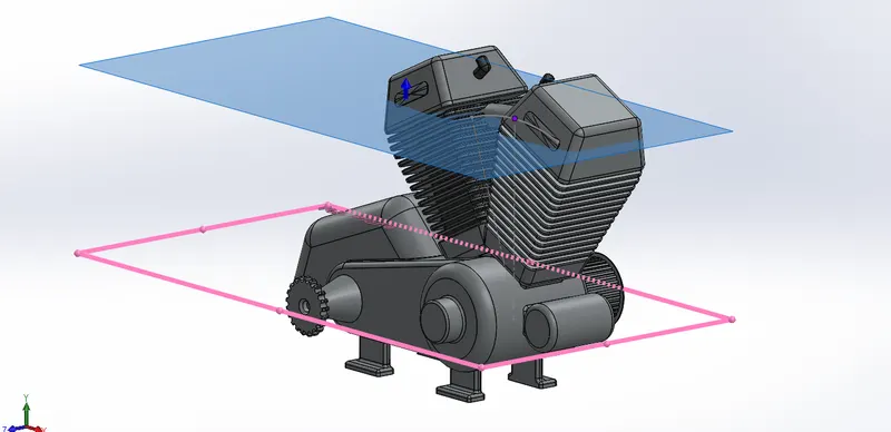
10. Reference planes and curves - Planes are created with reference to the sketches and profiles. A smooth curve is created by combining the two profiles.
11. Dome - Creating the circular emboss at the end of the object.
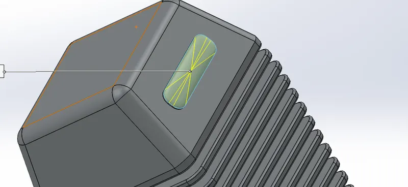
12. Combine and Split - Two individual bodies are combined using the combine tool. The split tool is used to cut the solid body using the sketch profile.
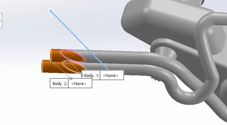
13. Shell - It is used to define the thickness of wall, hollows out a part, leaves the open the selected faces.
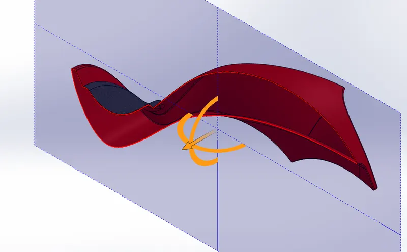
14. Mirror - Mirrors the 3D solids about the selected planes.
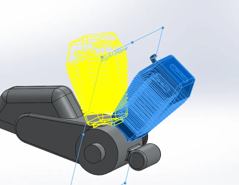
15. Boundary surface - Creates the bounded surface between the selected curves.
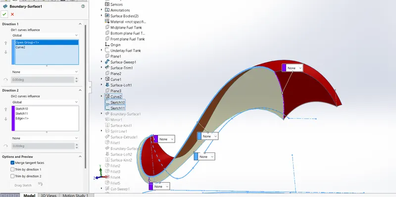
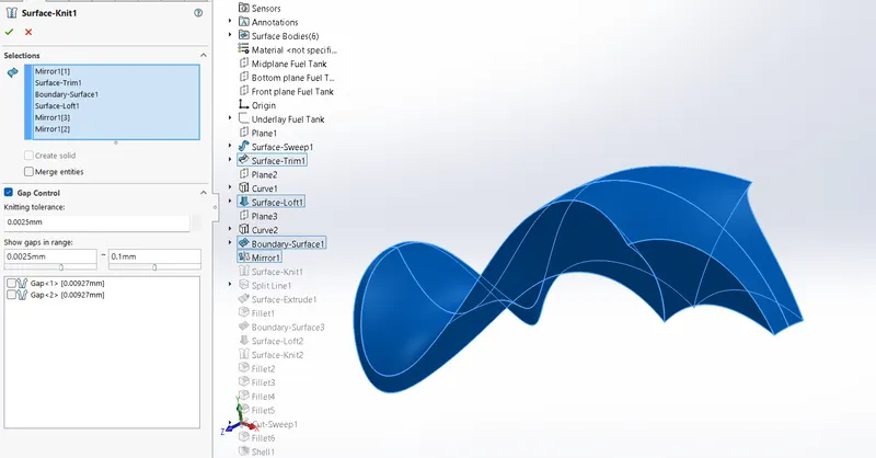
16. knit surface - Knit surface is used to knit the two free edges or open edges of the surfaces together also it reduces the gap between the two edges of the surface.
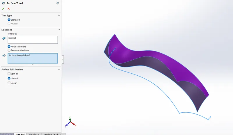
17. Surface Trim - Primarily used to cut away material from a surface and provides two modes, standard and mutual.
Description of modelled parts :
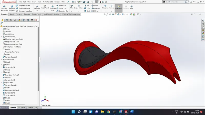
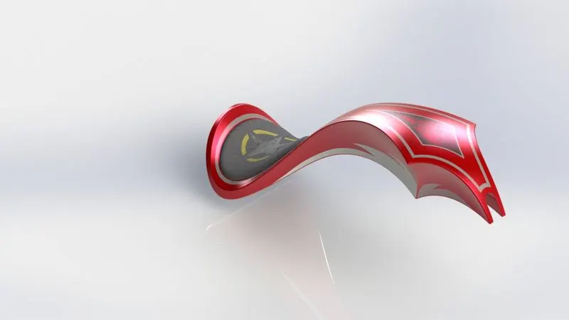
1. Fuel Tank or Gas Tank - The gas tank stores the fuel required to run the engine. The gas tank is completely designed using the surface modelling features such as extrude surface, knit surface, surface trim, loft surface, boundary surface etc.
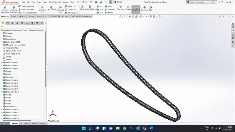
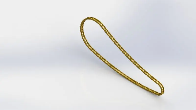
2. Chain - Chain is the power transmitting unit. In this chopper bike assembly, the chain is used to transfer the power from the engine sprocket to the rear wheel sprocket. First, the sketch blocks are created and are used whenever required in modelling of chain. The extruded sketch blocks are patterned using the curve driven pattern.
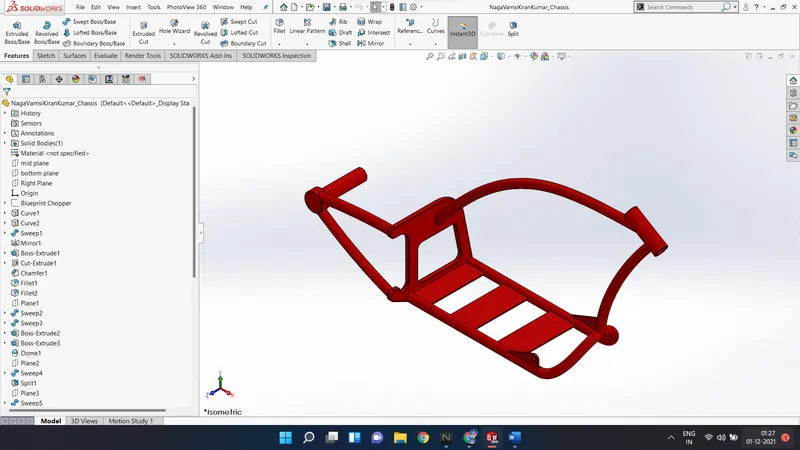
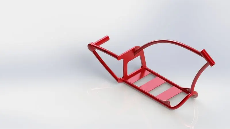
3. Chassis - The chassis is the main supporting member of a motorcycle. It supports the engine, tank, wheel, fork etc., and acts as the skeleton of the chopper bike. The features used are extrude, sweep, cut extrude, projected curves, etc.
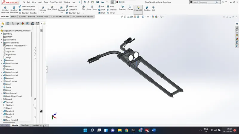
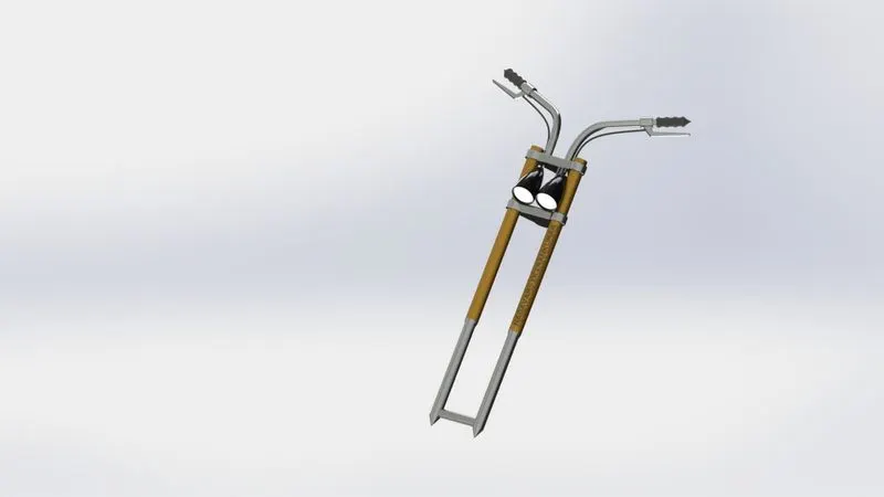
4. Front Fork - The structure which connects the chassis and the front wheel of the chopper bike. The fork consists of the head lamps, steering control of the bike and brake levers. The features used for this part are extruded boss, sweep, mirror, move or copy, projected curves, etc.
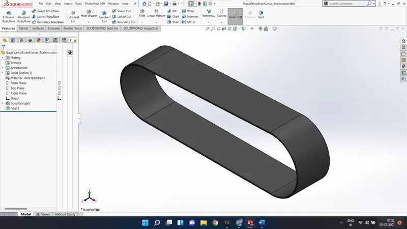
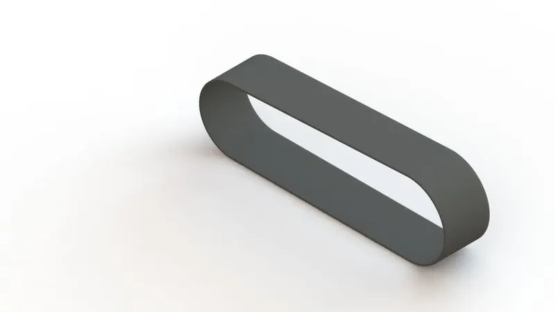
5. Transmission Belt - The transmission belt is used to transmit the power between the engine crank shaft to the transmission system of the chopper bike. The features used to design the transmission belt are extruded boss, fillet, etc.
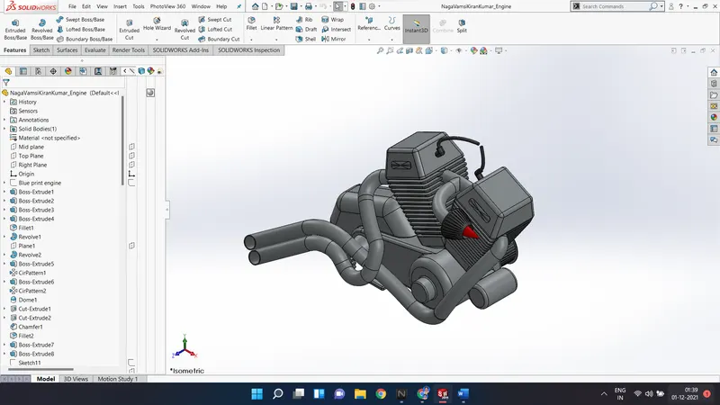
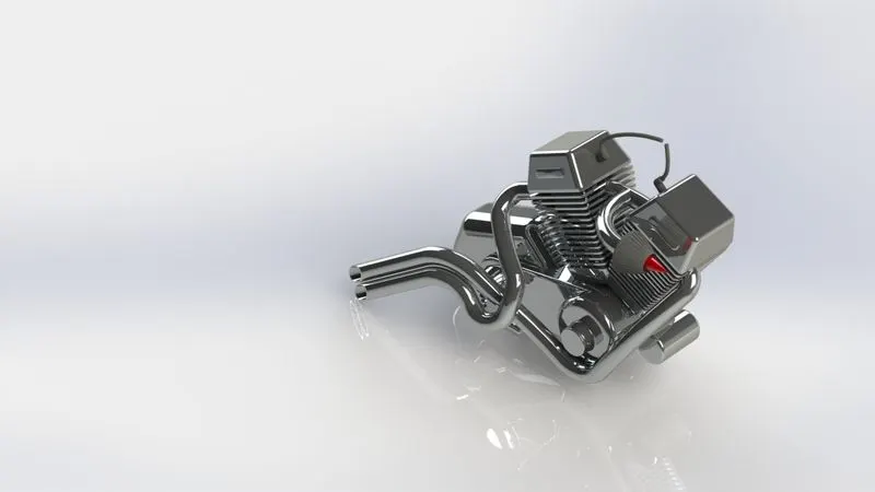
6. Engine - The heart of the chopper bike, which runs the entire motorcycle. Here, the engine is used is V-type. The is designed with air inlet manifold and with twin exhaust manifold. The various features used to design the engine are projected curves, extruded boss, sweep, offset, split, combine, etc.
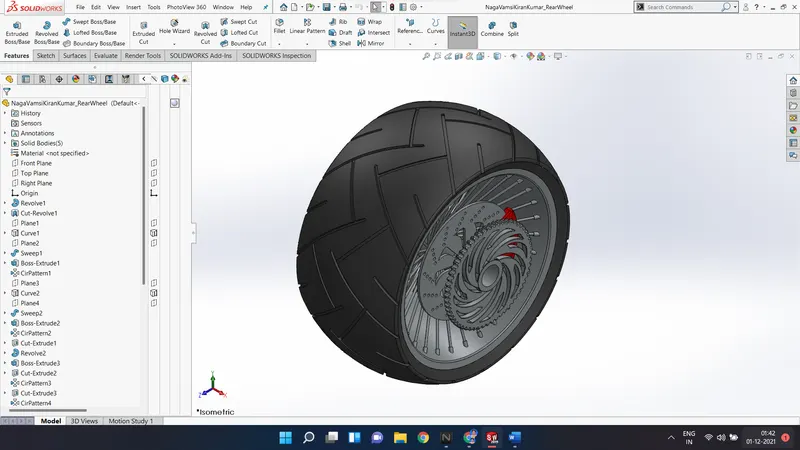
7. Rear wheel - The rear wheel consist of the tire, rotor, brake disk, chain sprocket and wheel rim. The various features used to design this part revolved boss, revolved cut, extruded cut, etc.
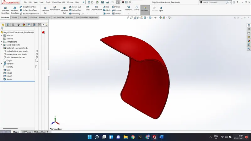
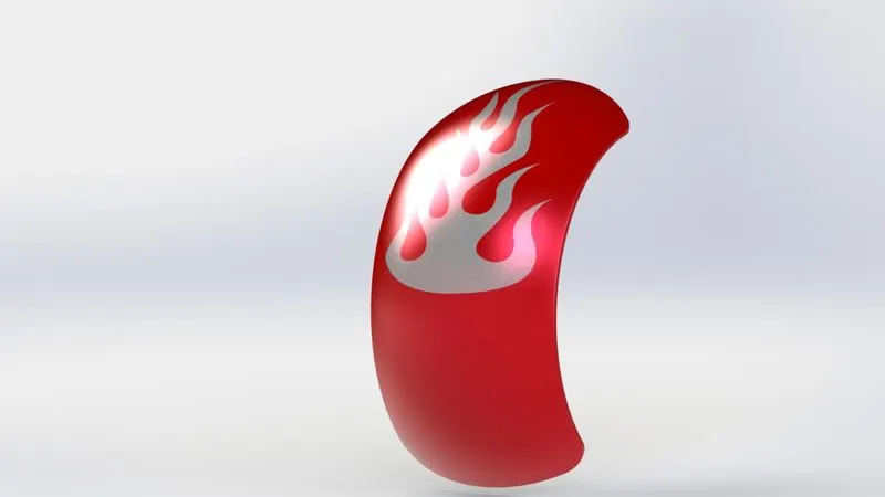
8. Rear fender - The rear fender is mounted on the above of the rear wheel. Its purpose is to protect the rider and motorcycle from mud, sand and liquids during rain.
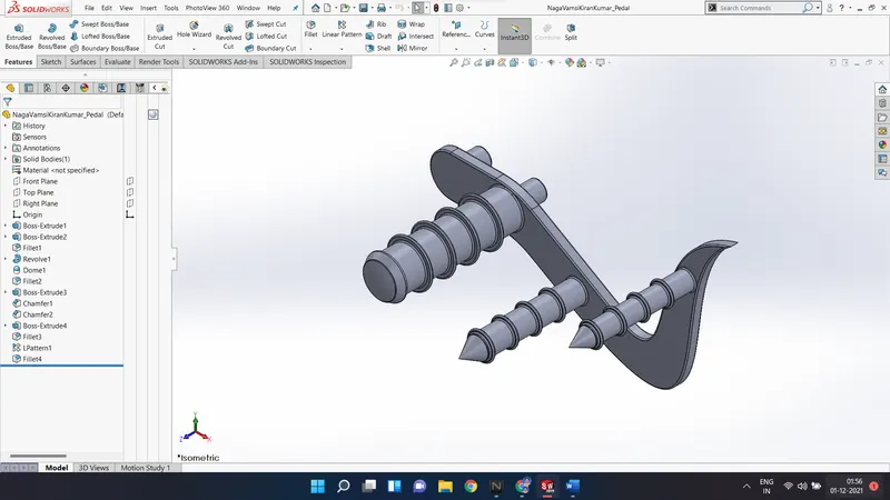
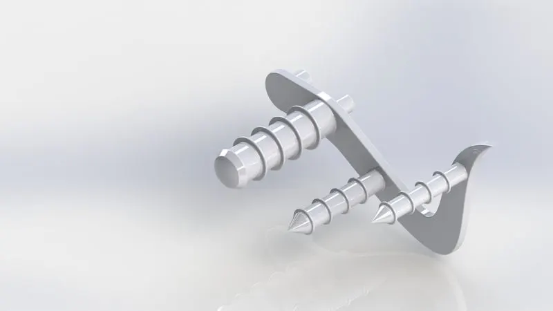
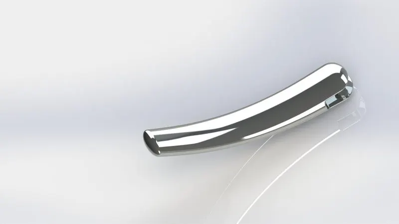
9. Pedal - Pedal or foot rest is used to rest the leg and to support them. The various features used to model the pedal are extruded boss, linear pattern, spline curves, etc.
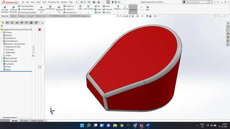
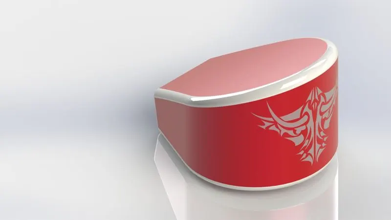
10. Oil tank - The oil tank is used to store lubricating oil which is required to lubricate and cool the engine components. The tools used to design the oil tank are extruded boss, shell, etc.
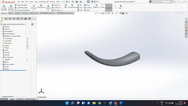
11. Kick stand - It is a supporting member which is used to stand the vehicle when it is in rest and makes contact with ground when stationary. Features used are Loft, extrude boss, dome, split, fillet, etc.
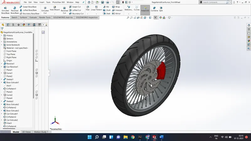
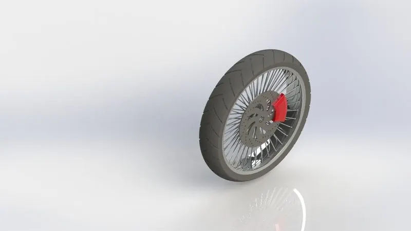
12. Front wheel - The front wheel which steers the vehicle. The features used to design the front wheel are revolved boss, revolved cut, extruded cut, circular pattern, etc.
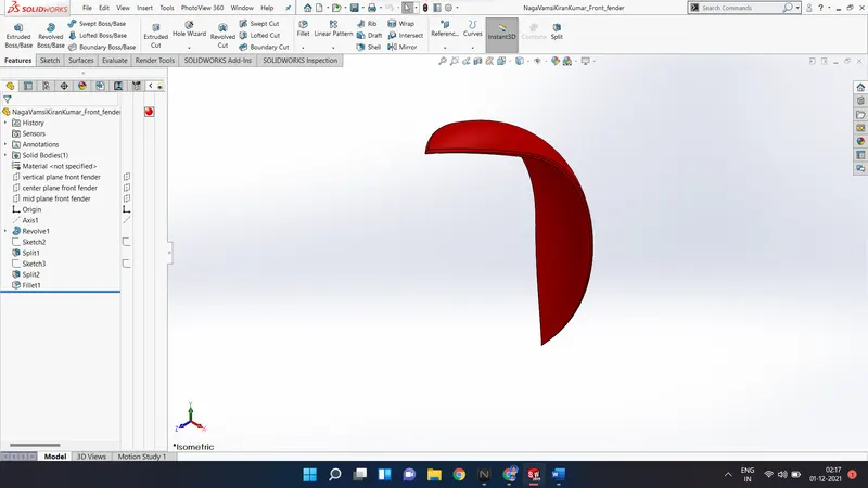
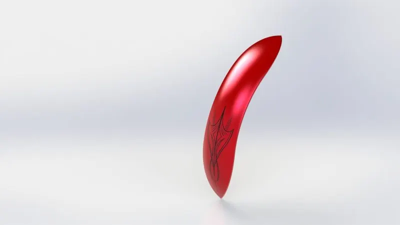
13. Front fender - The front fender is mounted on the front wheel of the chopper bike. Its purpose it to protect the motorcycle from mud, sand and dust. The main features used to design the fender are sweep, split, fillet, etc.
Assembly :
There are two types of approaches in assembly of a product. Top-down approach and bottom up approach. In American chopper bike design, bottom up approach is implemented. The individual parts are first designed, and then they are assembled later.
For assembling the chopper bike, all the individual part files are imported into the SolidWorks assembly environment, and they are related to each other with proper mates.
Mate creates the geometric relationship between the individual components. It nothing but defining the degree of freedom of a component. The various types of mates used in SolidWorks assembly are
1. Standard mates -
- Coincident
- Parallel
- Perpendicular
- Tangent
- Concentric
- Distance
- Angle
2. Mechanical mates -
- Symmetric
- Width
- Path mate
- Limit angle
3. Advanced mates -
- Cam
- Slot
- Hinge
- Gear
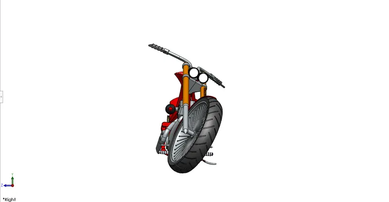
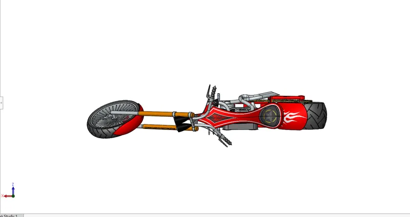
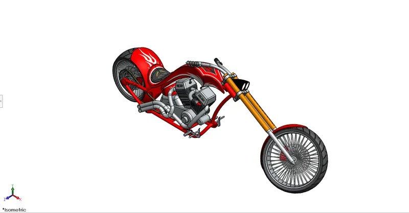
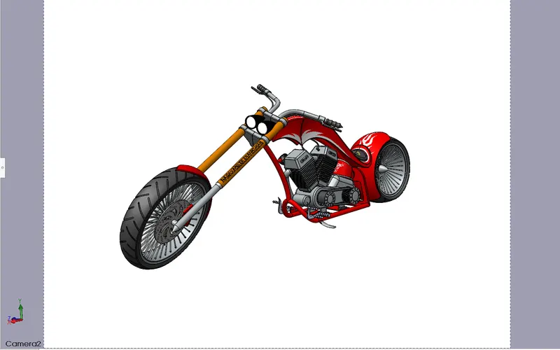
Assembly views of American Chopper bike :
Front view
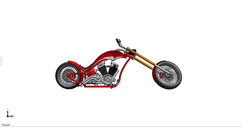
Side view
Top view
Isometric view
Camera view
Front Chopper Bike
Rendering :
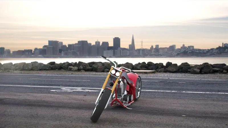
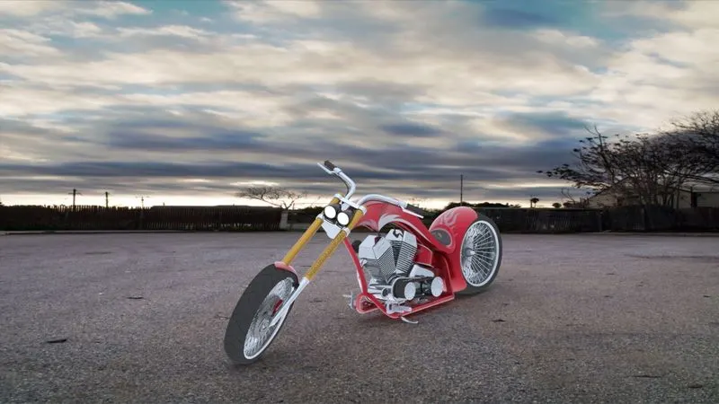
The photo realistic renders are created in SolidWorks using add-in called PhotoView 360. The rendering of the image include setting-up the environment, arranging the lights, setting up the scenes and creating the final view of the designed part. SolidWorks visualize is also an add-in which is used to high quality rendered images with minimum amount of time.
The rendered images of the Chopper parts shown below
Transmission Belt -
Engine -
Pedal -
Front wheel -
Pedal -
Rear fender -
Oil Tank -
Rear wheel -
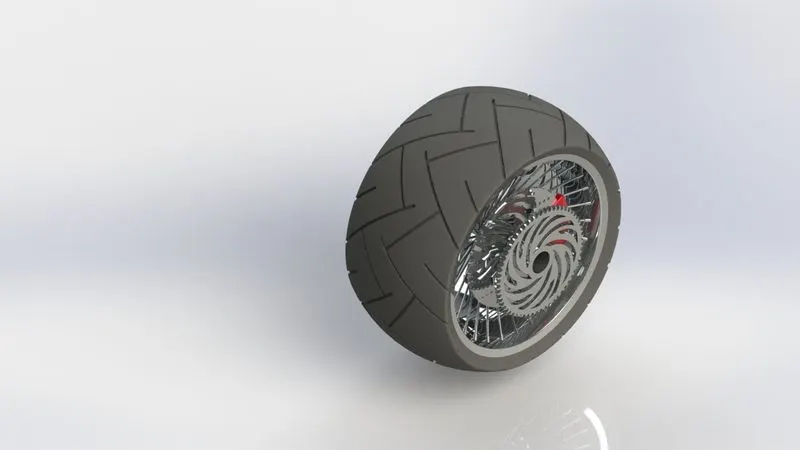
Gas Tank -
Chassis -
Front fender -
Fork -
Chain -
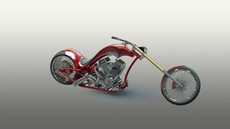
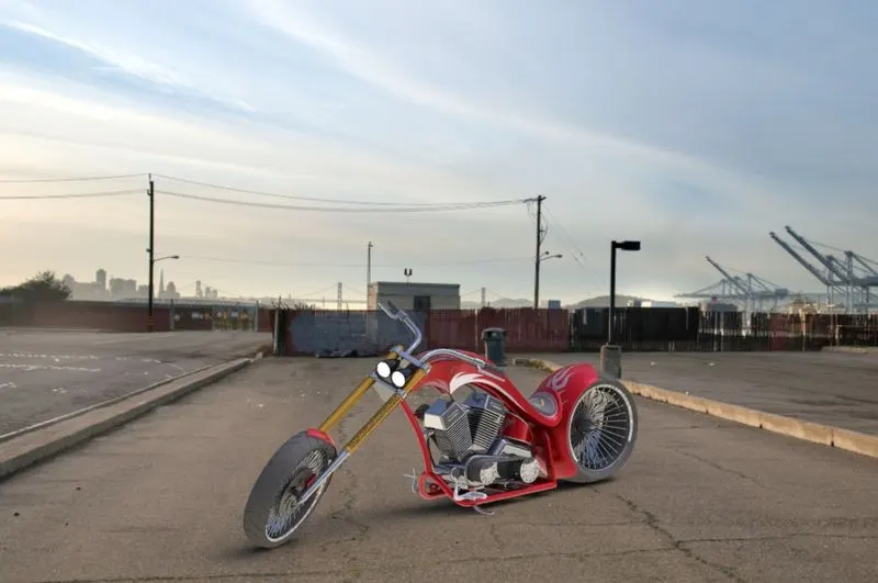
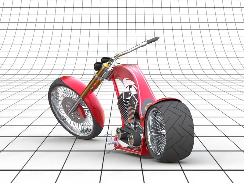
Rendered Images of the American Chopper Bike :
Conclusion :
The individual parts of the American Chopper bike are designed and are assembled using the SolidWorks. I have learned the use of various powerful part desgining tools in the SolidWorks environmnet. The assembly of the American Chopper bike is rendered in Photoview 360 are images are attached.
Link to all files --
https://drive.google.com/drive/folders/1HHWSUEnTKg4WAE16_AJUNyHJEwpwz15c?usp=sharing
THANK YOU