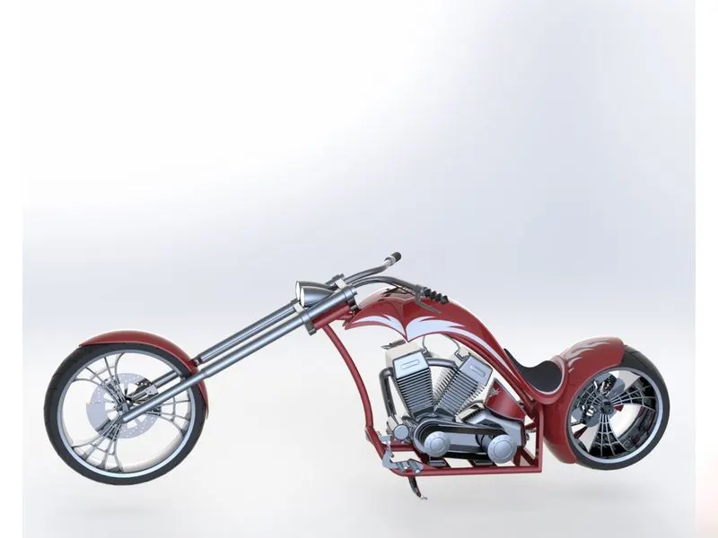
Photo Realistic Rendering
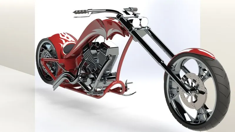
Modelling,Assembly and rendering of an American chopper
Objective:
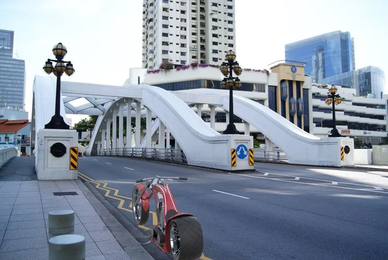
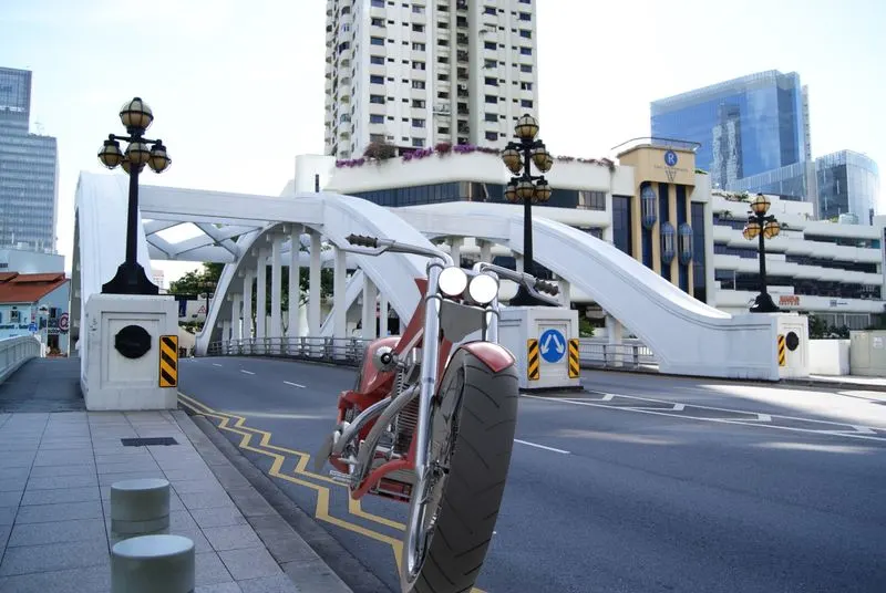
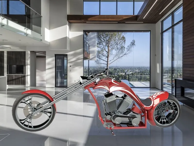
To modelling an American chopper by using solidworks and to render it with by solidworks visualize
Introduction:
The term "chopper" simply means to chop parts off of or modify a motorcycle, however over the years it has come to represent a particular style of modified motorcycle, usually with a raked and extended front end, lowered rear suspension or no rear suspension, tall handlebars and possibly a high sissy bar on the back.
Choppers evolved from bobbers in the 1940's and 1950's. Bobbers were basically stock bikes with the fenders bobbed or cut down, or even removed altogether. Indian motorcycles were typically modified into bobbers. This made them lighter, making them quicker, but also improved the look to many. The chopper was originally based on land speed record motorcycles and drag racing motorcycles, which had raked front ends, lowered suspension & frames, narrow front tires, small gas tanks and wide rear tires for traction.
Originally it was a motorcycle version of the hot rods and lakesters from the 1950's.Over time, the style was adopted for street motorcycles and certain concessions were made for comfort on the road, such as taller handlebars and a sissy bar, which enabled the bike to comfortably carry a passenger and gear. As choppers evolved through the 1960's and 1970's, many had elaborate custom paint, lots of chrome and detailed custom work. They became more art than transportation.
This project is deal with that how to modelling an American chopper by using solidworks and to render it with by solidworks visualize
Design methodology:
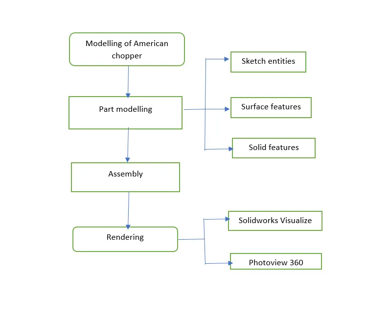
American chopper parts:
- Front fender
- Chasis
- Rear fender
- Front fork
- Gas tank
- Oil tank
- Front wheel
- Rear wheel
- Side stand
- Engine
- Pedal
- Chain
- Transmission belt
Features used:
- Solid features
- Boss extrude
- cut extrude
- Boss loft
- Revovle boss/base
- swept cut
- sweep
- fillet
- chamfer
- Mirror
- Split line
- projected curve
- circular pattern
- curve driven pattern
- linear pattern
- combine
- shell
- split
- Dome
- Surface features
- Loft surface
- swept surface
- surface extruded
- surface extend
- surface trim
- Boundary surface
Description:
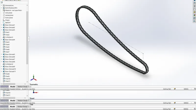
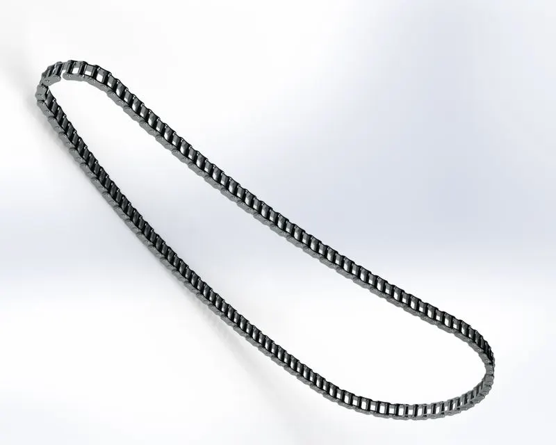
1. Chain
Features used: sketch entities,blocks, fillets, boss extruded ,linear pattern
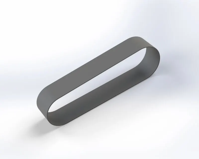
2.Transmission belt:
Features used: sketch entities, boss extruded, fillets, appearance
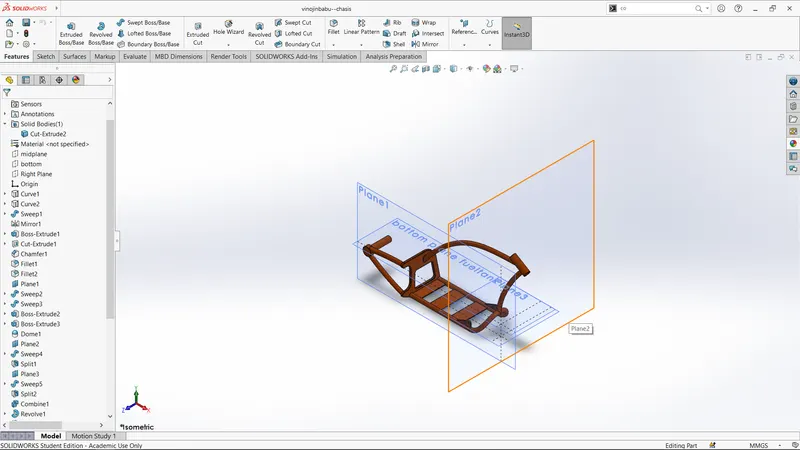
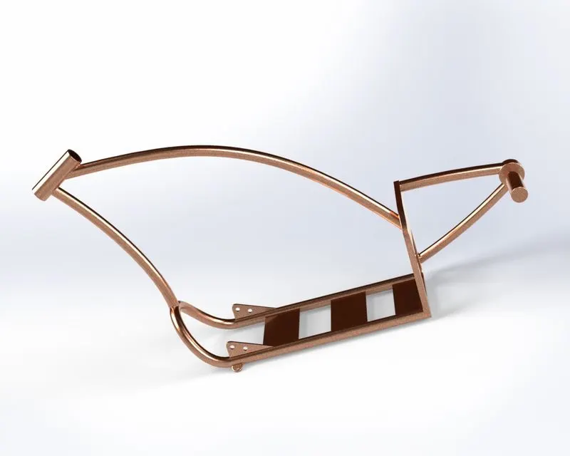
3.Chasis
Features used: sketch entities, boss extruded, fillets, Revovle boss/base, projected curve, combine,cut extruded
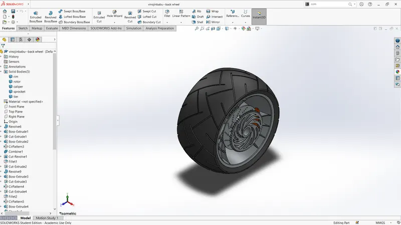
4.Rear wheel
Features used: sketch entities, boss extruded, fillets, Revovle boss/base,extruded cut, circular pattern, chamfer
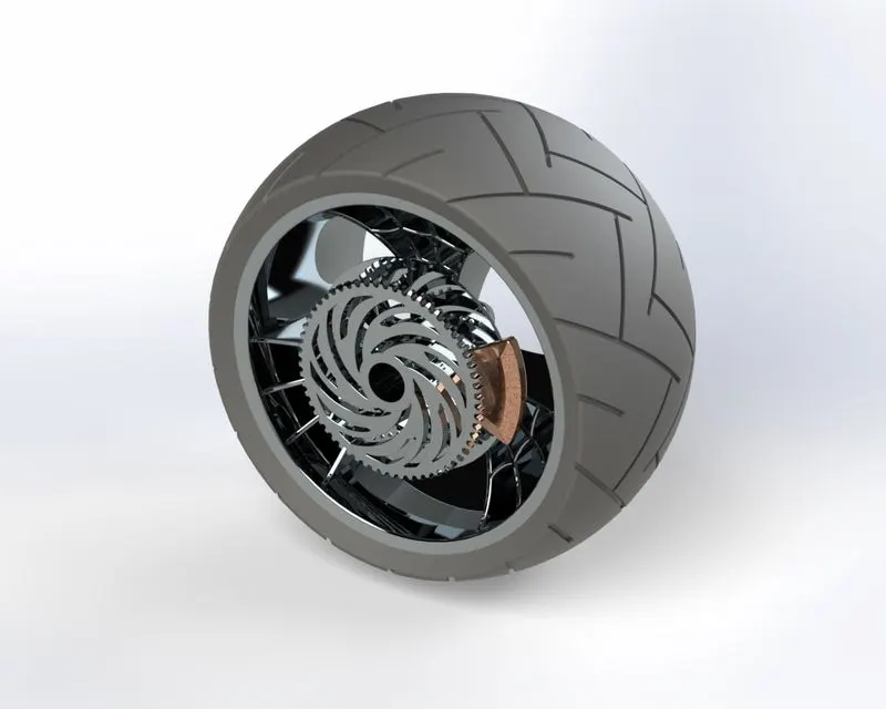
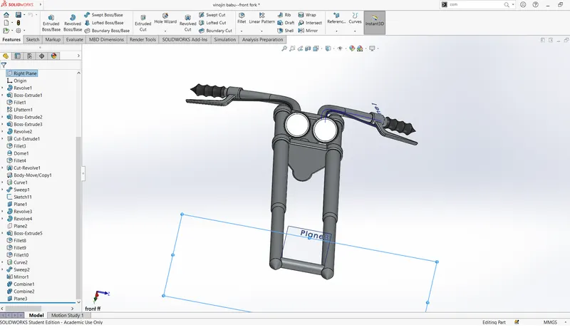
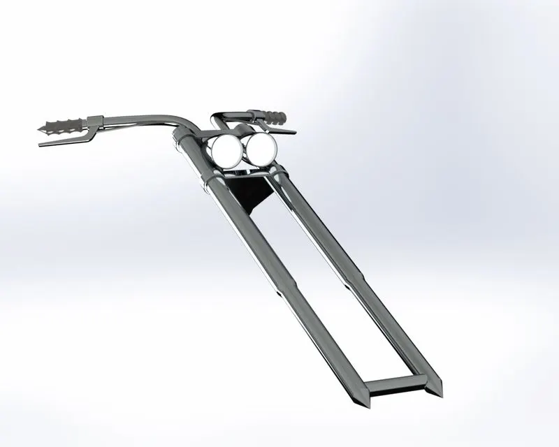
5.Front fork
Features used: sketch entities, boss extruded, fillets, Revovle boss/base,extruded cut,chamfer,projected curve,swept,mirror,linear pattern
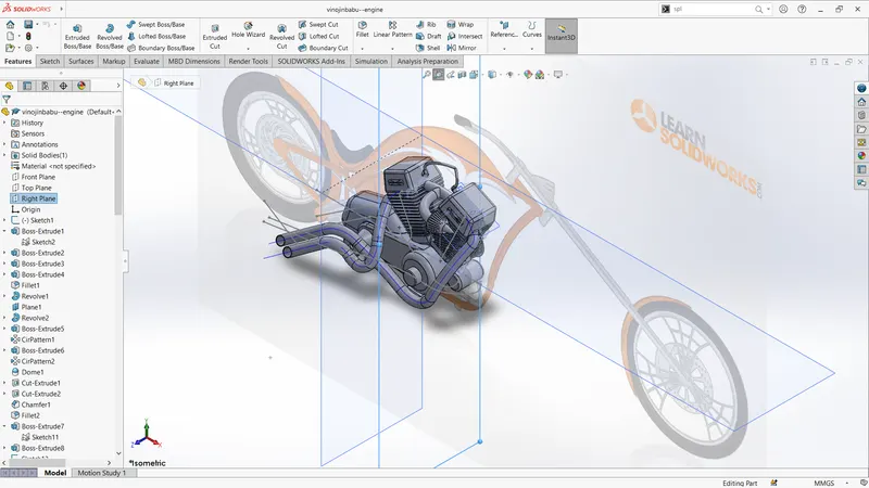
6.Engine
Features used: sketch entities, boss extruded, fillets, Revovle boss/base,extruded cut,chamfer,projected curve,swept,mirror,linear pattern,dome,cicular pattern
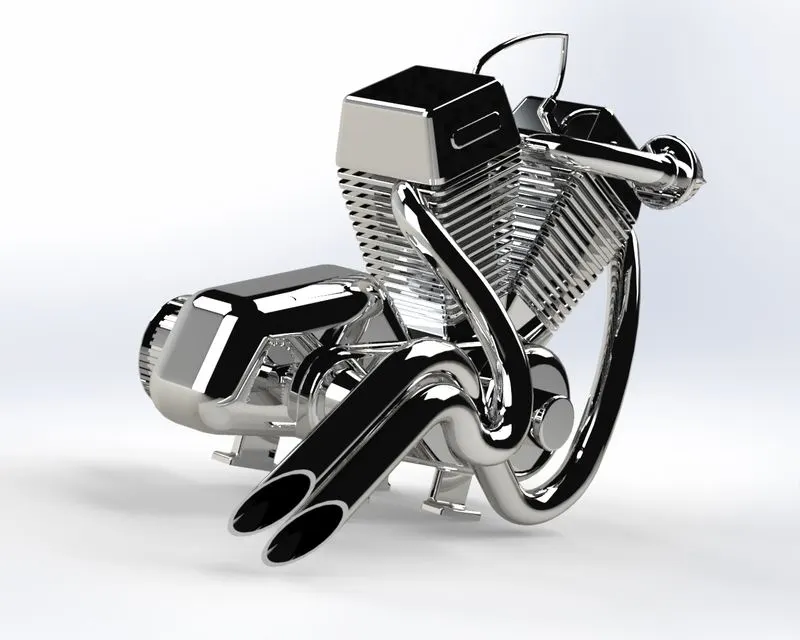
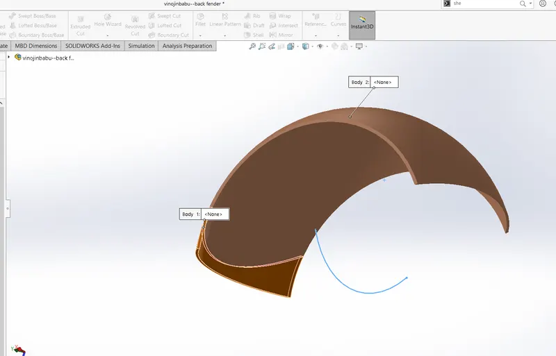
7.Back fender
Features used: sketch entities, fillets, Revovle boss/base,extruded cut
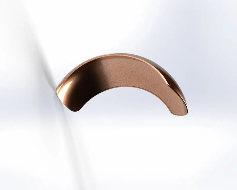
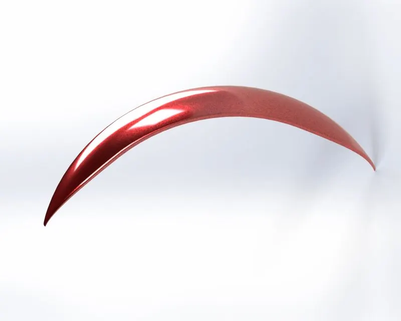
8.Front fender
Features used: sketch entities, fillets, Revovle boss/base,extruded cut
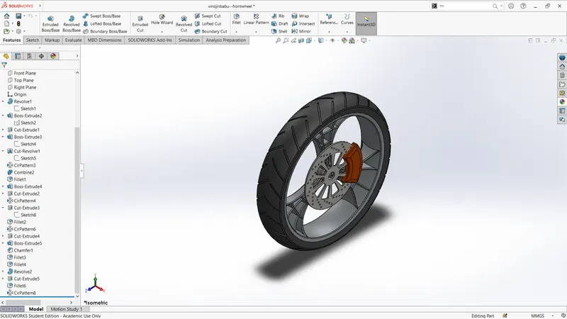
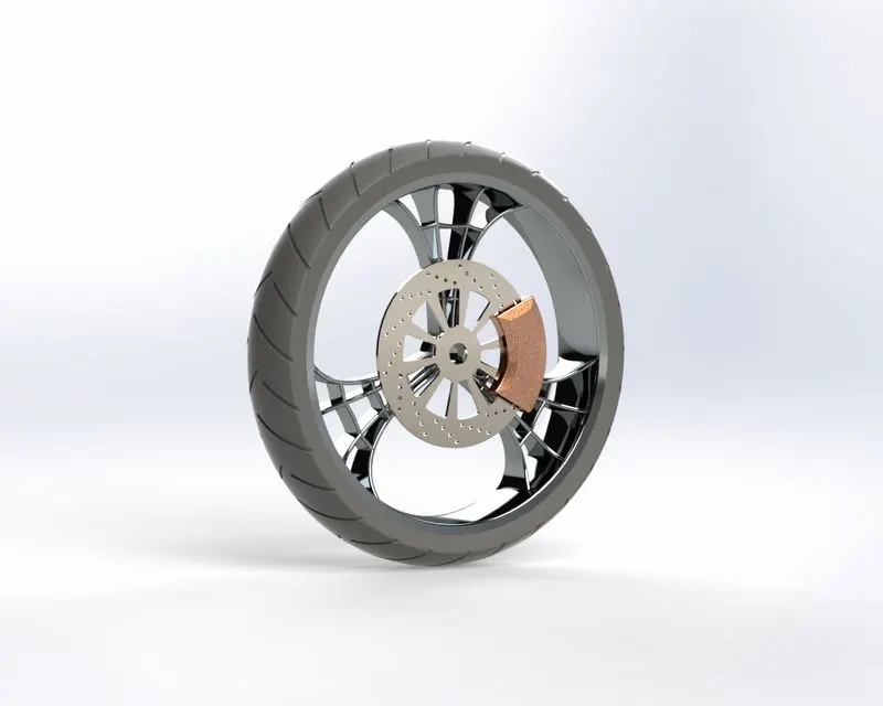
9.Front wheel
Features used: sketch entities, boss extruded, fillets, Revovle boss/base,extruded cut, circular pattern, chamfer
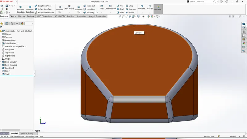
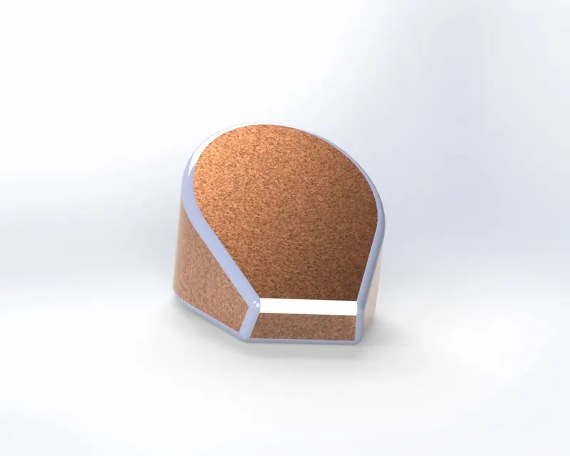
10.Oil tank
Features used: sketch entities, boss extruded, fillets,combine,shell
11.Kick stand
Features used: sketch entities, boss extruded, fillets, Revovle boss/base,extruded cut,chamfer
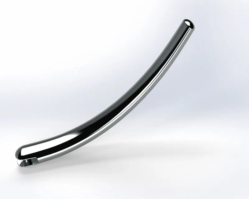
12.Fuel tank
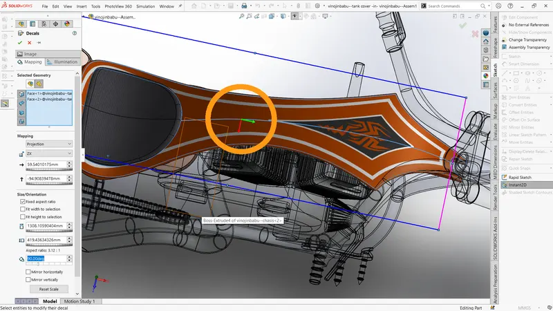
Features used: sketch entities, swept boss, fillets,loft surface, trim surface, swept cut, knit surface
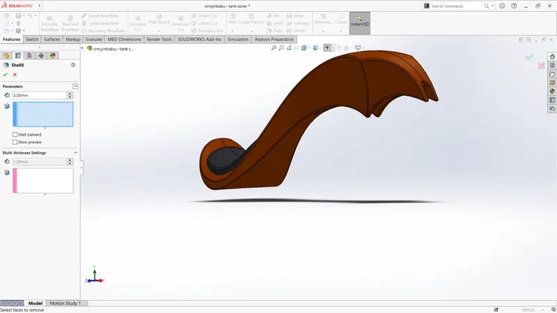
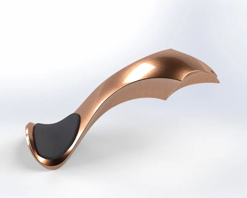
13.Pedal
Features used: sketch entities, boss extruded, fillets, Revovle boss/base,extruded cut,chamfer
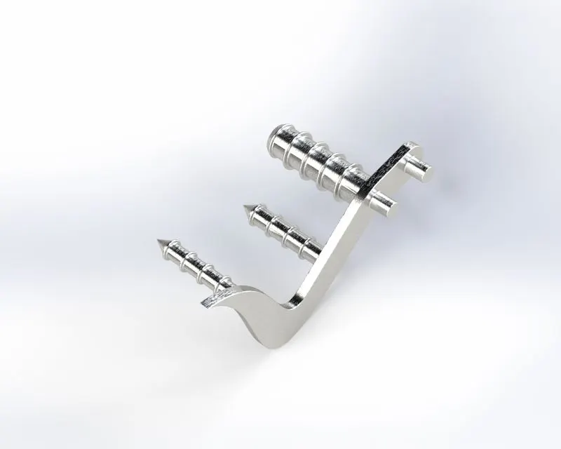
Assembly of Chopper
used mates:
- Angle mate
- coincident mate
- parallel and perpenticular mate
- concentric mate
- tangent mate
- lock mate
- distance mate
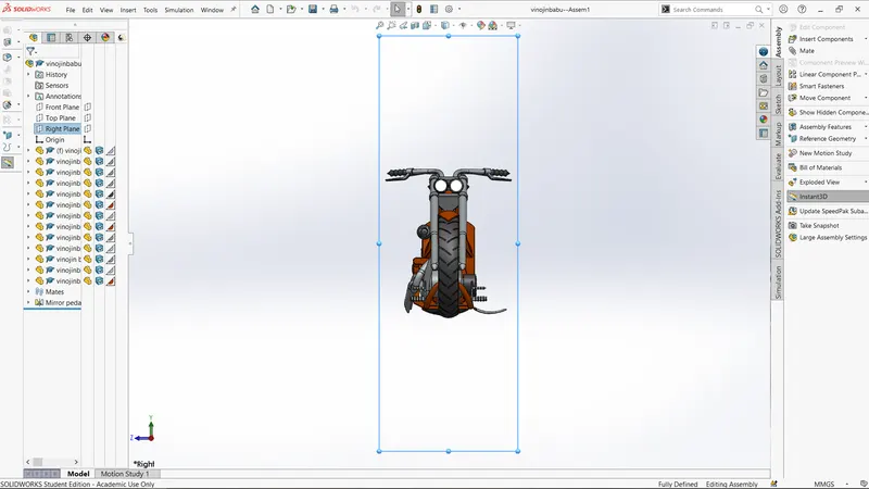
Front view
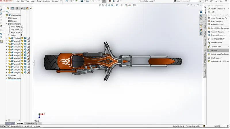
Top view
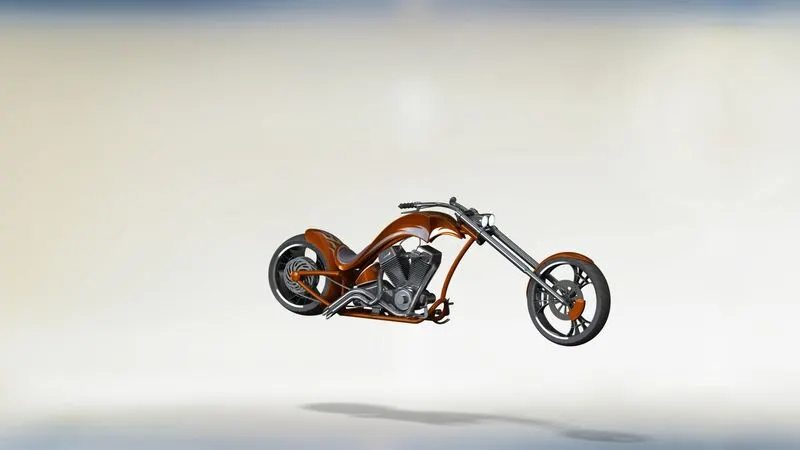
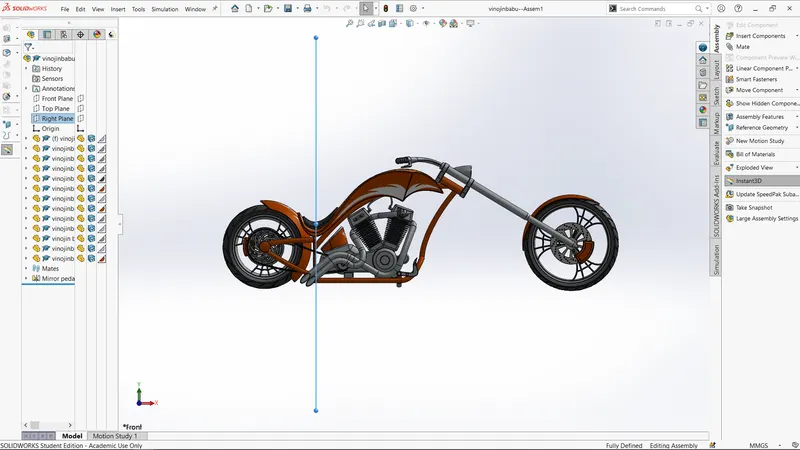
side view
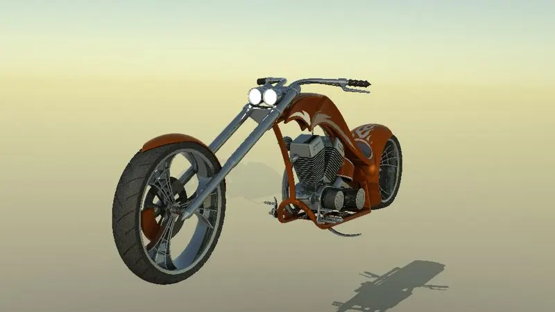
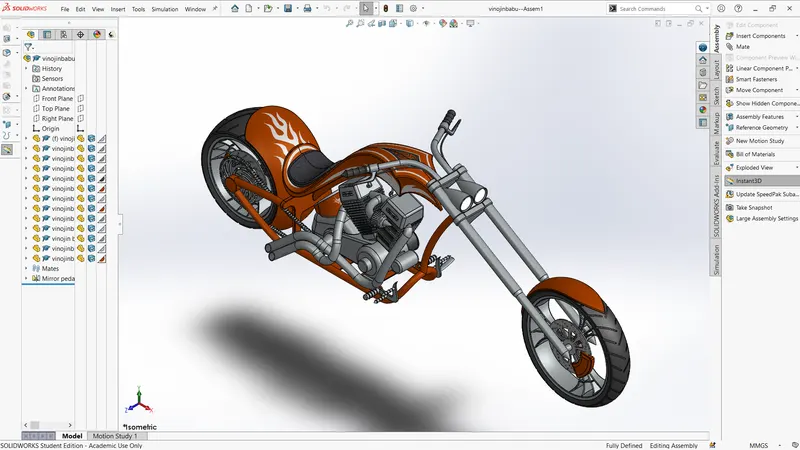
Isomatric view
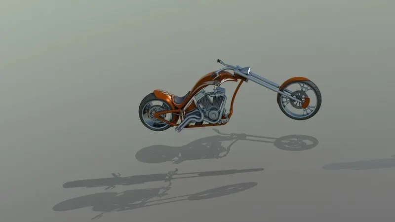
Rendering: