Photo Realistic Rendering
Project1: Part Modelling,Assembly And Photo-Realistic Rendering Of American Chopper.
- OBJECTIVE:
- To do the part modelling of all parts of American Chopper in solidworks.
- Get the knowledge of how to assemble all the parts in solidworks.
- Do the photo realistic rendering of the chopper in solidworks.
Introduction:
Hello Everyone,I am M Goverdhan Rao.Here I am explaining the entire methodology and also the features used in part modelling of all parts which are included in the American Chopper.
The Various parts which we are going to model are:
1.Transmission Belt.
2.Kick Stand.
3.Front Fender
4.Rear Fender
5.Chain
6.Oil Tank
7.Pedal
8.Front Wheel
9.Rear Wheel
10.Front Fork
11.Chasis
12.Engine
13.Gas Tank
- Design Approach:
There are two types of approaches in soidwoRKS.
1.Top Down Assembly Approach:
In Top Down assembly approach most of the Individual part modelling and assembly is done in assembly file (SLDASM).
2.Bottom Up Assembly Approach :
In Bottom up assembly approach the parts are modelled in individual part file (SLDPRT) file and the assembly of parts are done in assembly file (SLDASM).
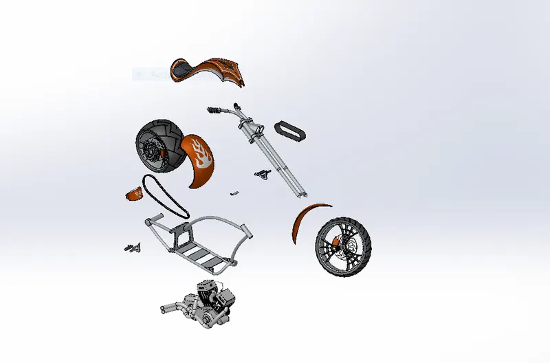
EXPLODED VIEW OF AMERICAN CHOPPER:
FEATURES AND TOOLS USED INN THE DESIGN OF THE AMERICAN CHOPPER:
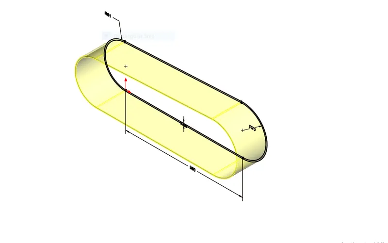
1.BOSS EXTRUDE:
The Boss Extrude feature is a basic feature available in features tab in the solidworks. For Extruding a sketch the sketch must should be fully closed there should not be an open loop .
2.REVOLVE BOSS/BASE:
The Revolve Boss/Base feature is used to make a cylindrical body from a sketch for this we must require a axis or plane or sketch about which we make the skecth to revolve.
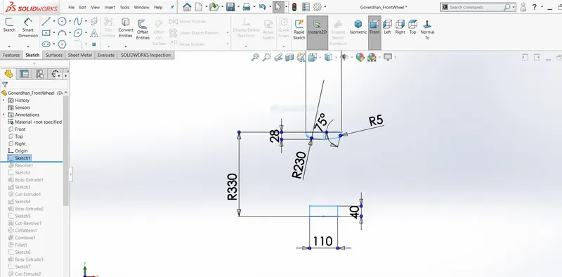
Fig: Shows the skecth for Revolve Boss/Base
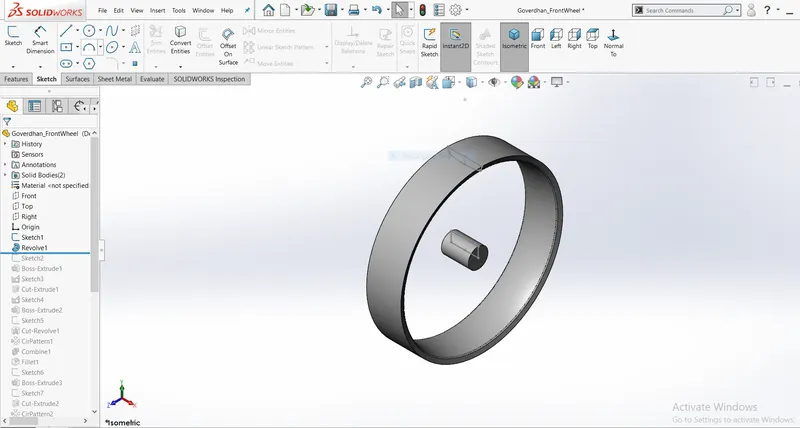
Fig: Using Revolve Bose/Base.
3.CIRCULAR PATTERN:
By using Circular Pattern we can use the same feature and can make as many as patterns by giving reference as circle.
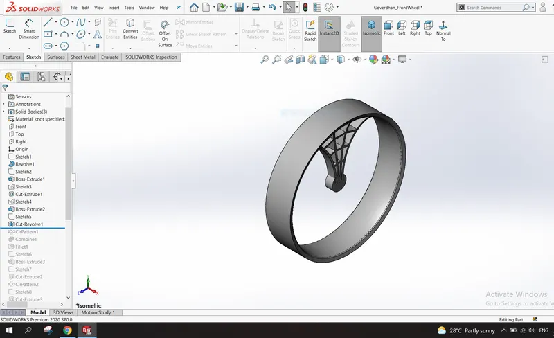
Fig: Before Applying Circular Pattern.
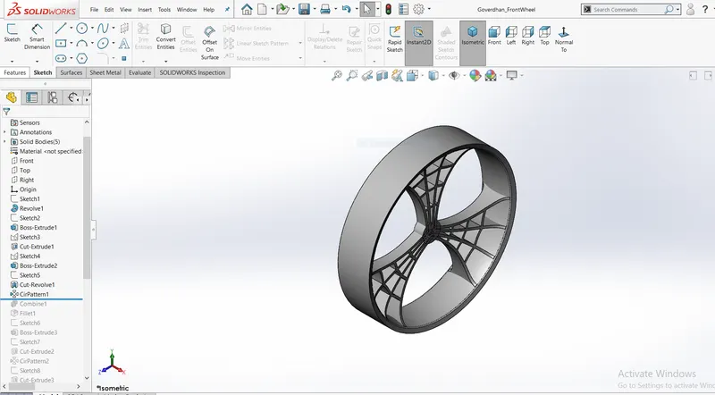
Fig : After Applying Circular Pattern.
4.COMBINE:
Combine feature is used to add,subtract or create a common solid body of two separate bodies.
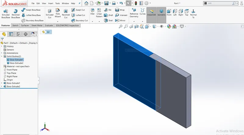
Fig : Before Using Combine Feature.
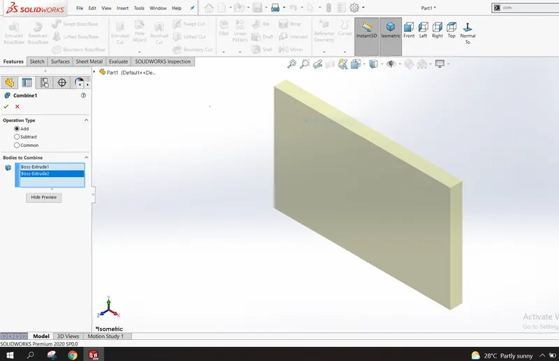
Fig : Using ADD Operation.
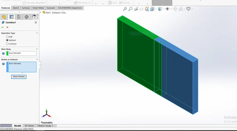
Fig : Using SUBTRACT Operation.
5. DOME:
Dome feature is located in Insert>Features>Dome. It is used to create a dome shape without any 2D complex sketch.
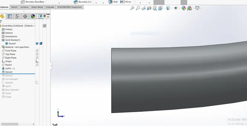
Fig : Before Using Dome Feature.
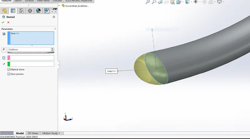
Fig : After Applying Dome Feature
6.FILLET:
Fillet gives a smooth edges by removing sharpen one's. There are four types of fillet options available in solidworks.
1. Constant Size Fillet.
2. Variable Size Fillet.
3. Face Fillet.
4. Full Round Fillet.
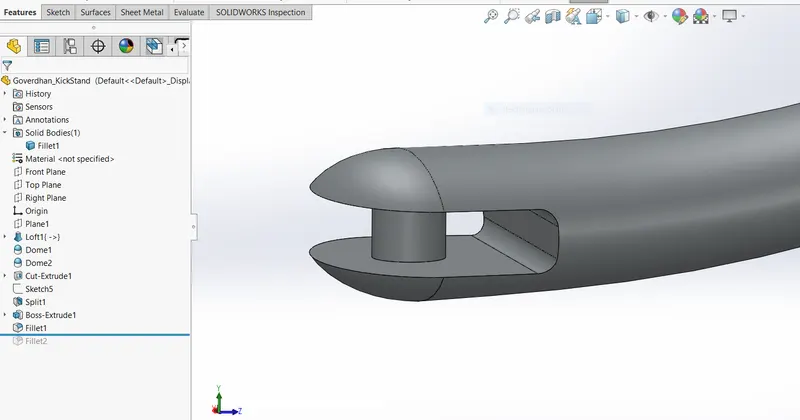
Fig : Before Applying Fillet.
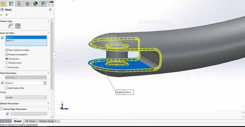
Fig : After Applying Fillet.
7.EXTRUDE CUT:
The Extrude Cut command is used to create a cut in the solid body.
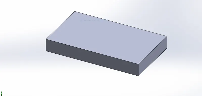
Fig : Before Applying Extrude Cut.
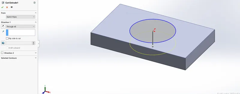
Fig : After Applying Extrude Cut.
8.SHELL :
Shell feature is used to create a hollow part from a solid body by varying thickness.
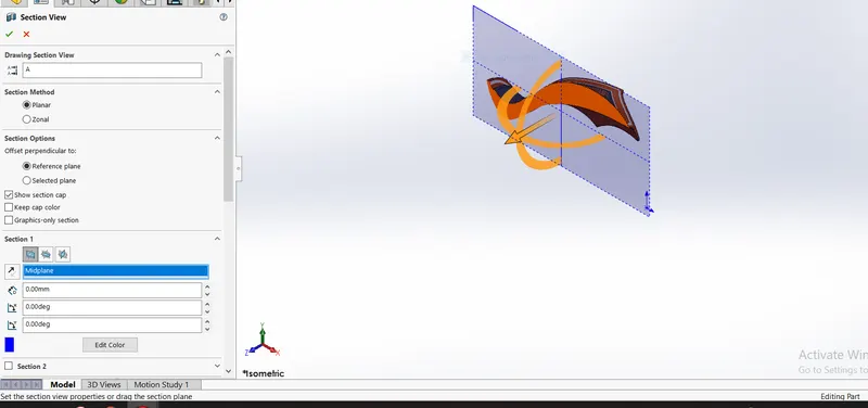
Fig : Before Appying Shell Feature.
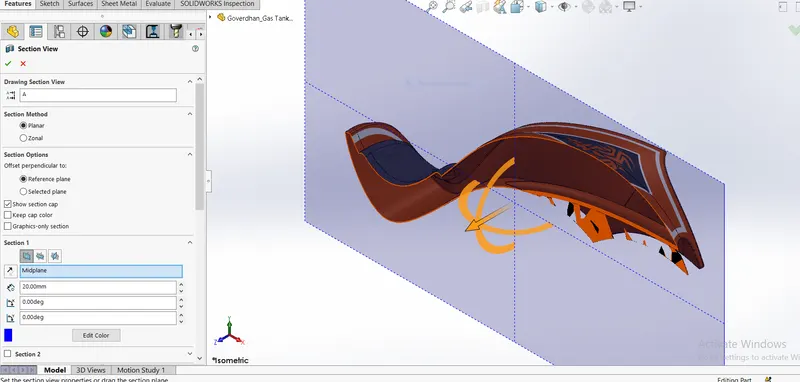
Fig : After Appying Shell Feature.
9.MIRROR:
Mirror Feature is used to mirror a body or feature about a plane,axis or line.
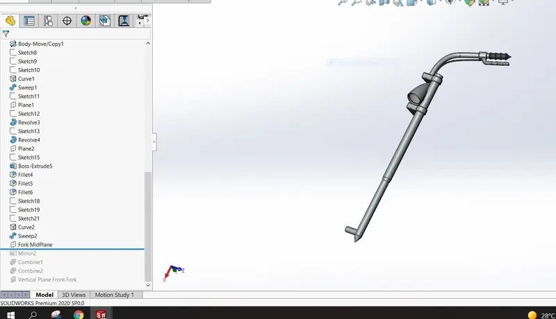
Fig : Before Using Mirror Feature.
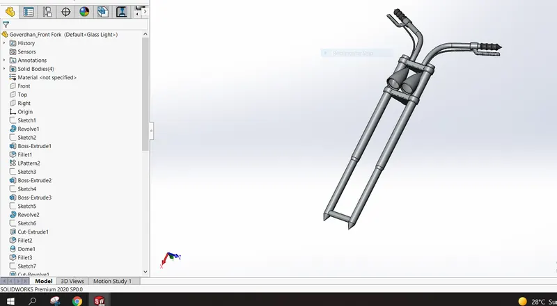
Fig : After Using Mirror Feature.
10.PROJECTED CURVE:
Projected Curve is a 3D curve option available in solidworks which is created by using two 2D curves and projected on to a face / surface. There are two options for projected curve
1. Sketch On Sketch
2.Sketch On Face.
Following is the example of sketch on sketch option.
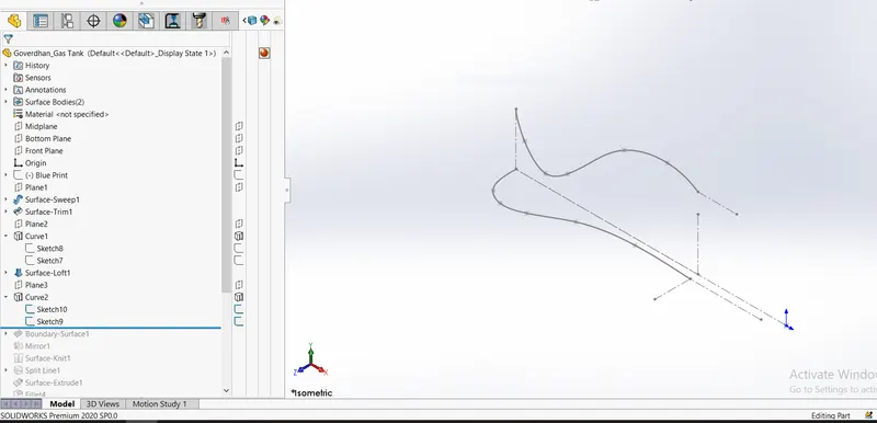
Fig: Before Using Projected Curve(showing two sketches using for sketch on sketch option)
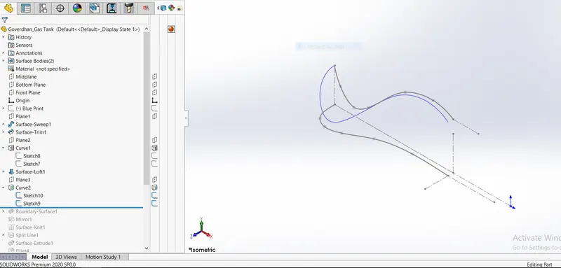
Fig: After Using Projected Curve. (Blue Curve is the projected curve).
Details Of Parts Used In Assembly Of American Chopper:
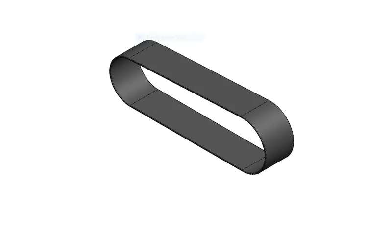
1. Transmission Belt:
The Transmission Belt is used to transfer the power from one pulley to another.The features used in this part modelling are
- Boss Extrude
- Fillet
Material applied in the appearance of Transmission Belt is Matte Rubber.
2. KICK STAND:
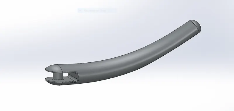
In this part modelling I have used to ellipse and a spline as guide curve for using loft feature. Dome is also used in design. Material applied in the appearance of kickstand is chrome.The features used in this part modelling are
- Loft
- Dome
- Extrude Cut
- Split
- Boss Extrude
3.FRONT FENDER:
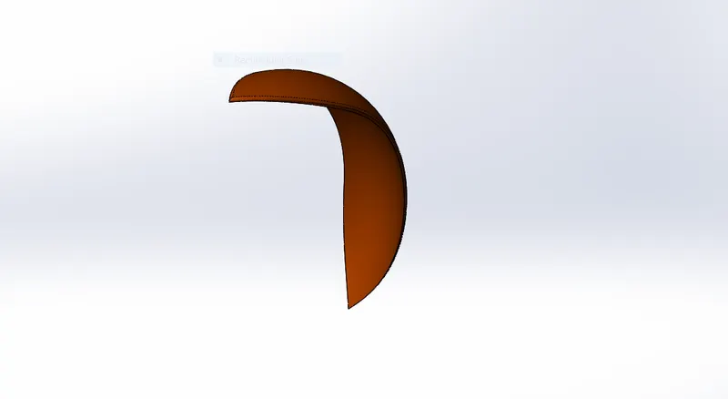
Fender is used to protect the driver from mud, water as well as engine and other parts.The features used in this part modelling are
- 3 Point Arc
- Revolve
- Split
- Fillet
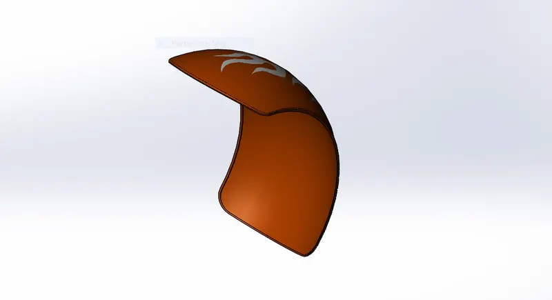
4. REAR FENDER :
It is designed by sketchig the 3 point arc and revolving around a axis.And at last I have a shell feature to accommodate rear tyre.
.The features used in this part modelling are
- 3 Point Arc
- Revolve
- Split
- Fillet
- Shell
5.CHAIN:
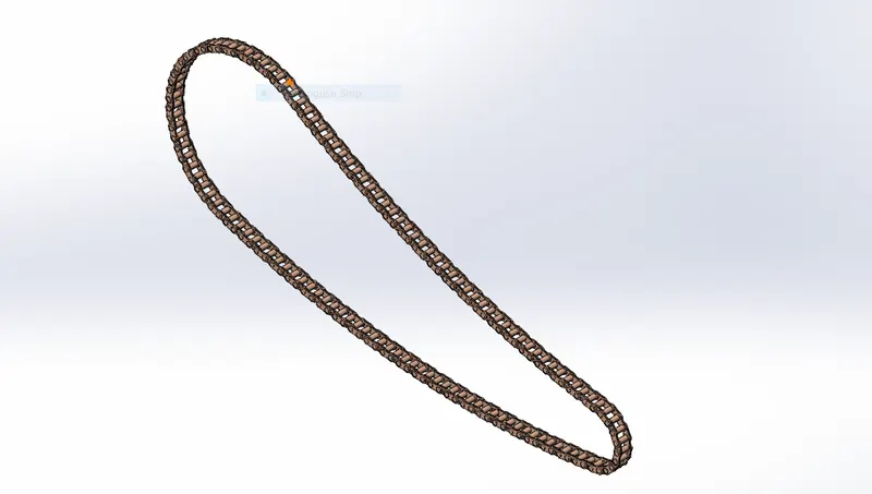
Chain outline is created by using 3 point arc and lines. The inner and outer faces of plates are created and made blockes by block command and patterned on the chain sketch.
The features used in this part modelling are
- 3 Point Arc
- Slot
- Boss Extrude
- Blocks
- Curve Driven Pattern
- Mirror
- Fillet
6.OIL TANK:
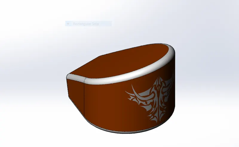
Oil Tank is created by using the sketch and by boss extruding it.Then the two boss extruded features are combined using combine command and shell command is used to create a hollow oil tank.The features used in this part modelling are
- Boss Extrude
- Combine
- Fillet
- Shell
7.PEDAL:
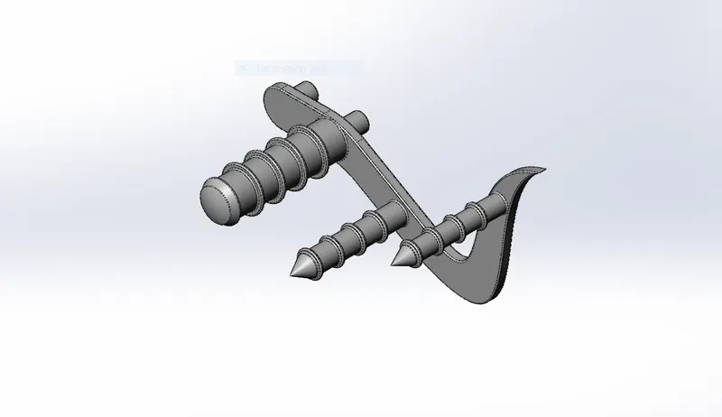
The pedal basic sketch is drawn and extruded it and the lever is created by using revolve command . Dome command is used to give a good look to lever and chamfer is used to give that pointed shape to front part of pedal. Finally linear pattern is created and fillet is applied.
The features used in this part modelling are
- Boss Extrude
- Revolve Boss Base
- Dome
- Chamfer
- Fillet
- Linear Pattern
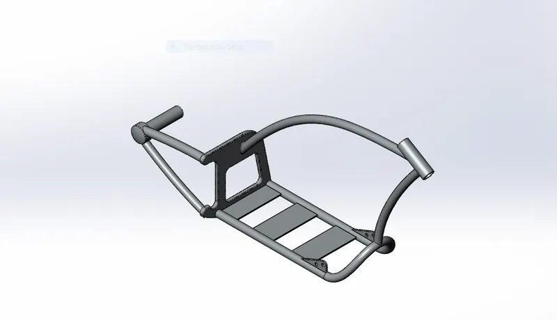
8.CHASIS
Chasis is the most important part as the whole load is carried by the chasis .The basic sketch outline is drawn by using blue print of american chopper.Two curves are drawn on different planes and projected curve command is used to give the front part chasis. By drawing the sweep profile in the front right plane and selecting the curve we can make a sweep profile by using sweep command.
The features used in this part modelling are
- Sketch Picture
- Projected Curve
- Sweep
- Mirror
- Fillet
- Chamfer
- Dome
- Split
- Linear Pattern
- Combine
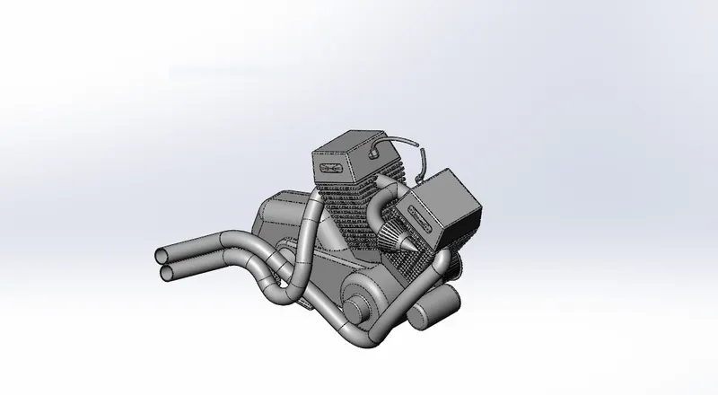
10 ENGINE:
Engine is the main part to run a bike. The same sketch picture is used to draw a outline of Engine.
The features used in this part modelling are
- Boss Extrude
- Fillet
- Revolve
- Dome
- Extrude Cut
- Mirror
- Linear Pattern
- Circular Pattern
- Split
- Sweep
- Composite Curve
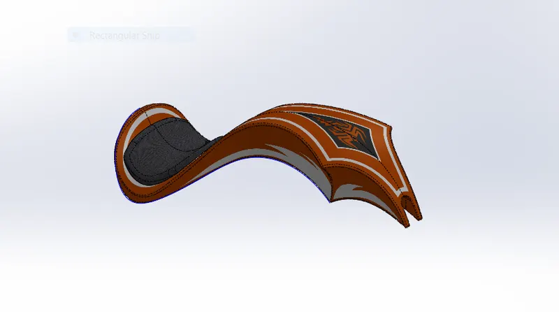
11. GAS TANK:
The features used in this part modelling are
- Surface Loft
- Boundary Surface
- Mirror
- Split Line
- Surface Extrude
- Knit
- Fillet
- Swept Cut
- Shell
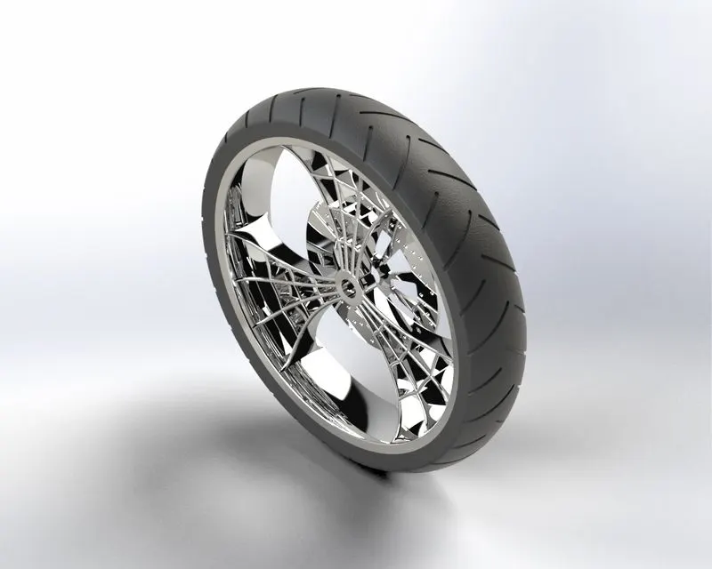
12 FRONT WHEEL:
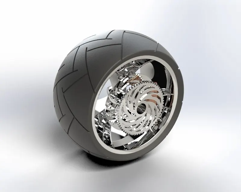
13. REAR WHEEL:
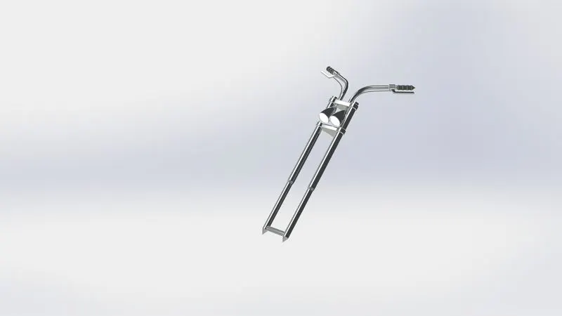
14. FRONT FORK:
ASSEMBLY:
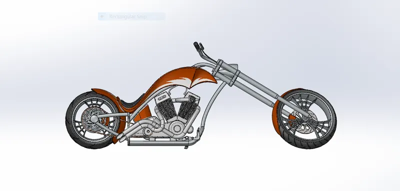
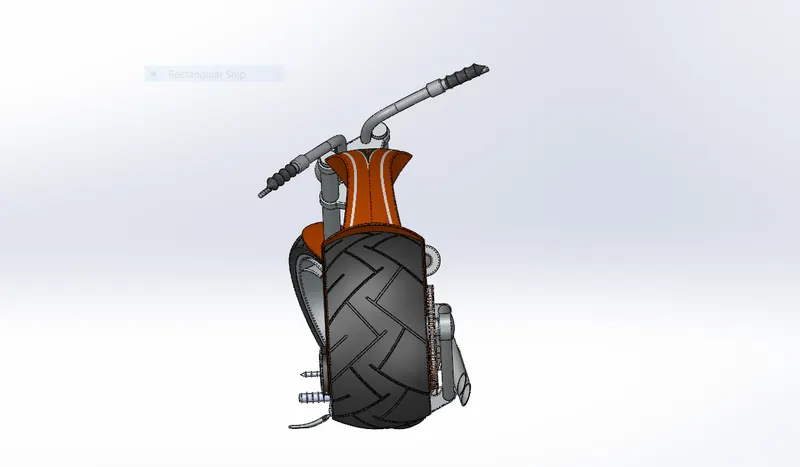
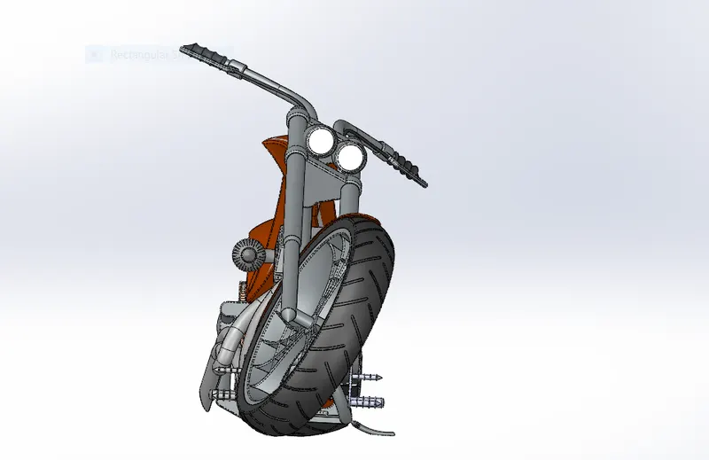
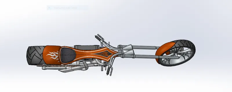
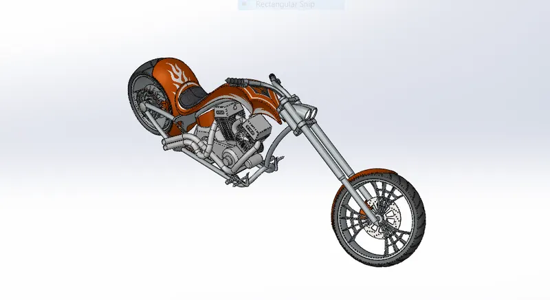
Assembly is the final step where every part of bike we modelled is assembled by using different mates and here I followed Bottom Up Assembly Approach and made sure that every part is
linked with chasis so that if we any changes in chasis location all others parts change according.
FRONT VIEW
LEFT VIEW:
RIGHT VIEW:
TOP VIEW:
ISOMETRIC VIEW:
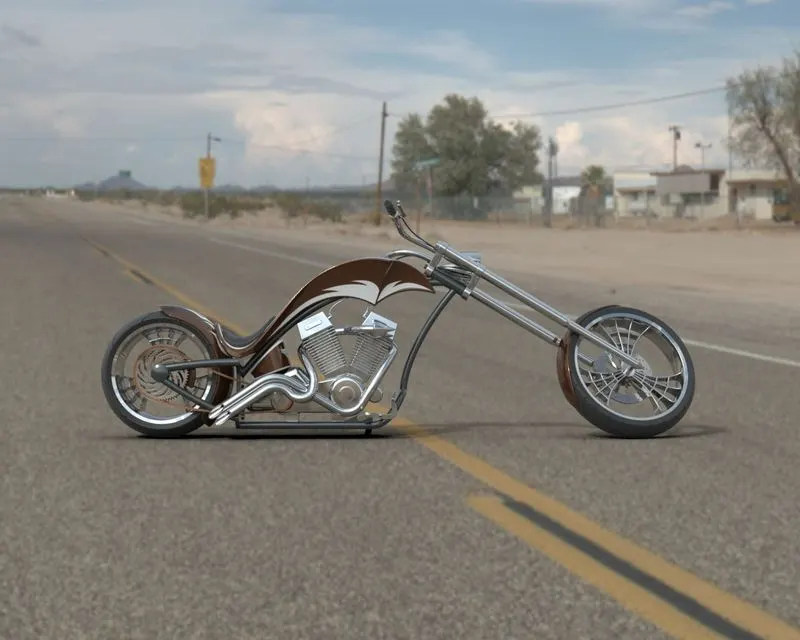
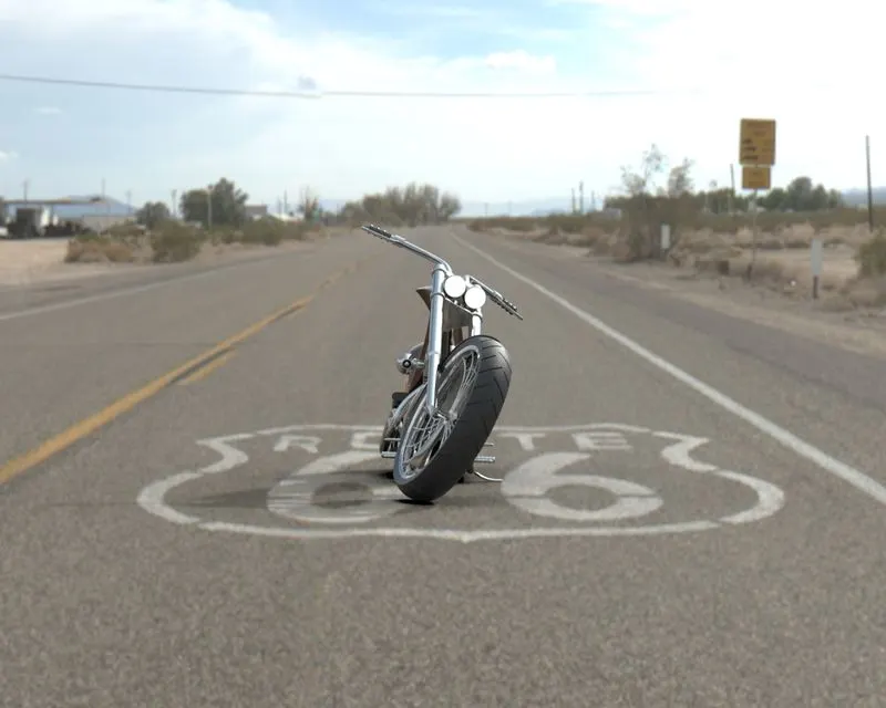
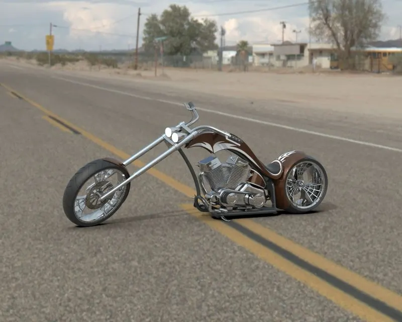
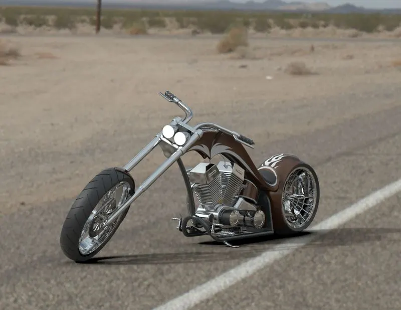
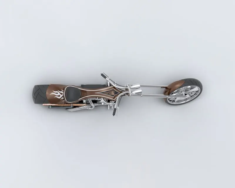
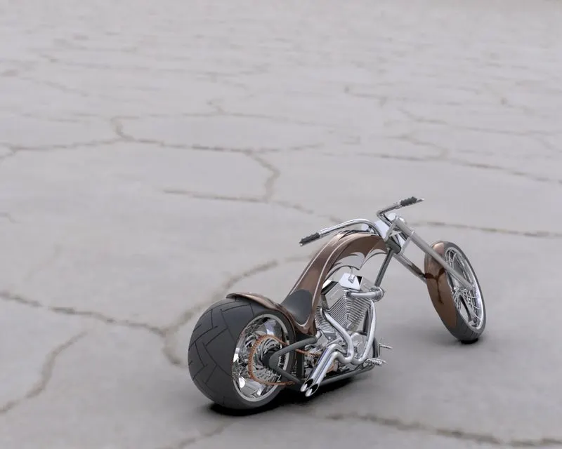
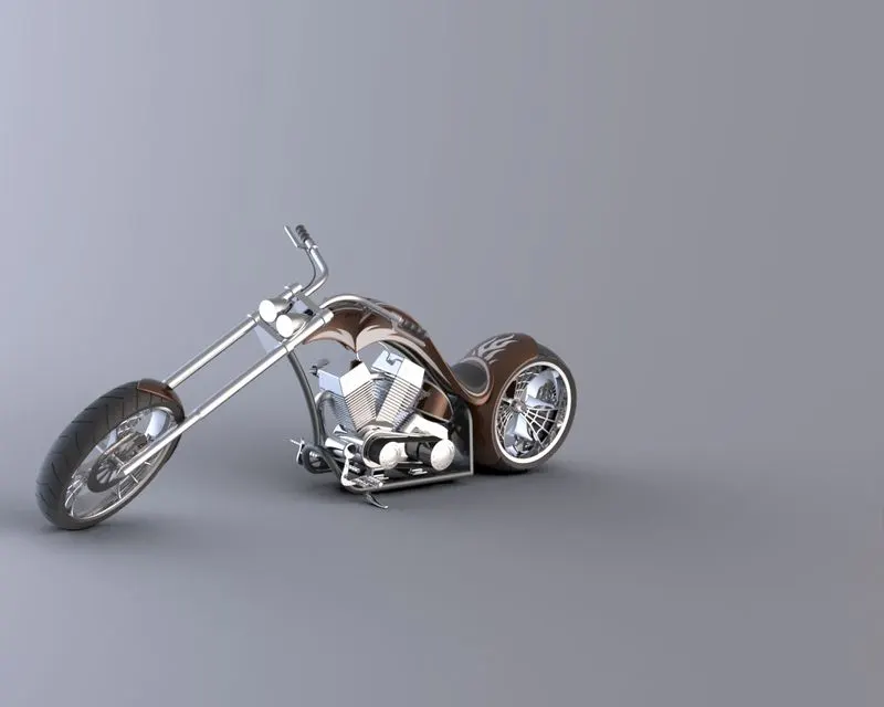
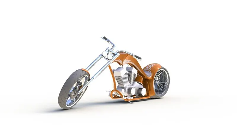
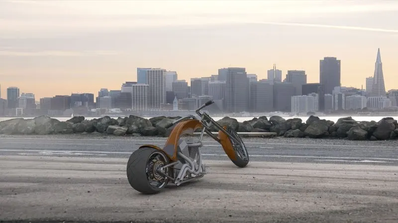
RENDERING:Rendering is the photo realistic appearance given to any product by changing scenes and environment.
FRONT VIEW
RIGHT VIEW:
ISOMETRIC VIEW:
CAMERA VIEW:
TOP VIEW:
CONCLUSION:
Hence I have modelled entire American Chopper using solidworks and assembled the parts. By using solidworks visualization and photoview360 I made to look the model as realistic as we can by different scenes and environments.