Photo Realistic Rendering
Ultimate SOLIDWORKS course from Skill Lync
Project American Chopper 3D model creation
Introduction
This project is about learning to use a 3D modelisation software called Solidworks. Made by Dassault system, Solidworks has became an industrie standard when it comes to mechanical design and modeling. along my education and career, I first begun my learning of this program back in 2000. I saw right away its great capabilities and attractive user interface. Solidworks is greatly used in the manufacturing industrie, for machine design, structural components, sheet metal processing, automation/robotics and so on.
In this particular class, a good number of possiblities were covered, when it comes to 3D modeling and redering. The project American Chopper is a very good choice. The complexity of the 3D model is high and challenging and, at the same time, the result is totally beatiful and rewarding.
Objectives
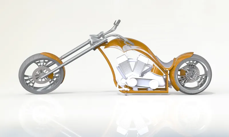
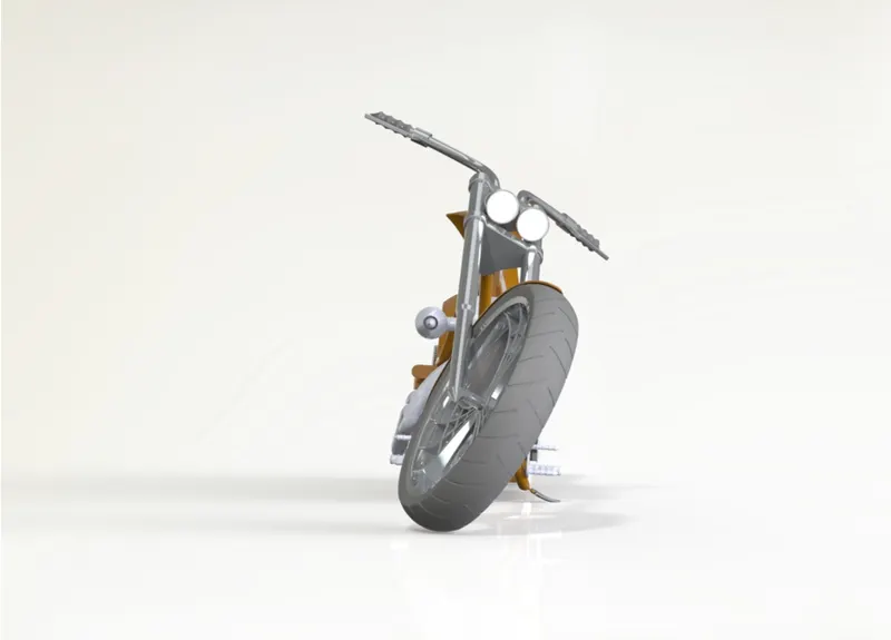
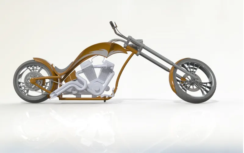
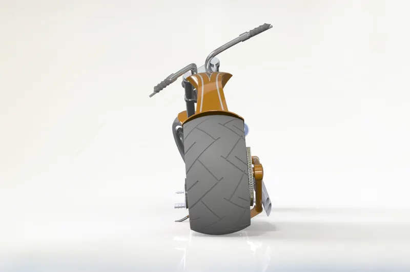
The overal objective is to learn to use Solidworks to design and complete a 3D model that looks like a picture of the actual concept. In order to achieve this, the course has for objective to provide learning in all the steps necessary.
- Becoming familiar with the User Interface.
- Creating templates having the proper settings when creating a new part or assembly
- Creating a new part
- Creating a sketch on the different reference planes possible
- Creating a solid 3D model using the basic features, such as extrude, cut-extrude, sweep,filet, array
- Using a blueprint as a reference to produce a model from a designer drawing or picture
- Creating complex 3D model, using features like spline, project curve, split
- Modeling a complex components in surface, using the following features, suface sweep, surface trim, surface loft, surface knit
- Applying specific appearances to, parts, surface and features
- Applying stickers on finished surfaces on the parts
- Creating an assembly for our model from the parts
- Using different types of mates, coincident, parallel, distance, angle, width and advanced mating options
- Preparing the model for photo render, adjusting the position, lighting, scene parameter
- Using Photoview 360 and Visualize to produce a photo realistic render
Design Aproach
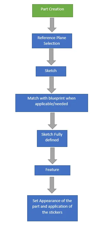
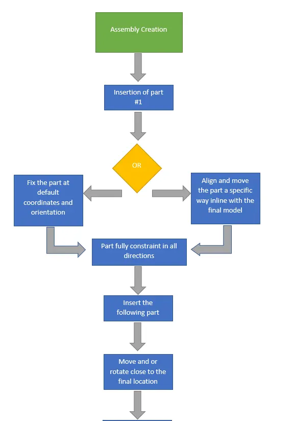
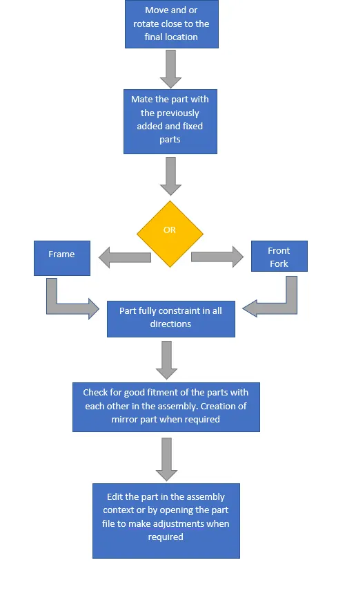
In this project, the approach used was mostly going from the bottom up. Basically, we worked first at the component level. The components design, dimensions shapes and appearance were well known. This allowed us to make the 3D model for each of the part, individually. The blueprint drawing from the designer was used as a reference to ensure our 3D model follows the style, curvers and look. We applied specific appearances and stickers on the finished parts. Once the parts all completed, the next stage of the model began; the assembly file. Using the proper template, a new assembly file was created. Then it was ready to receive the first part. The frame was purposely chosen to be the first one to buld our assemnbly. The chopper is mostly build from the frame up. The frame was properly oriented and fixed in the coordiate system of the assembly 3D space. The frame being fixed, it was now possible to bring in other parts of the chopper and attached them. This operation is done by the mean of the assembly feature Mate. Mate is how we reference the parts to one an other or to the assembly origine. The mates were in place, assemnling the parts either to the frame or the front fork. For instance, the front wheel and fender are moving together with fork. The fork was matted with the frame, using mates option that allow it to pivot over its center axis. In the assembly process, the propper fitment of parts and overal design quality were checked. One of the part, the kickstand had to be adjusted to better suit the chopper. This was done by either opening the part file, or by editing the part in the assembly context, making it easier since the whole assembly is visible while working on the part. Also, a part was completly created in the assembly, rather than from scratch. The left hand pedal stand was created in the assembly from the right hand pedal stand.
Design Aproach flow chart - Parts creation
Design Aproach flow chart - Assembly creation
Details of the design - Features used
-Boss Extrude
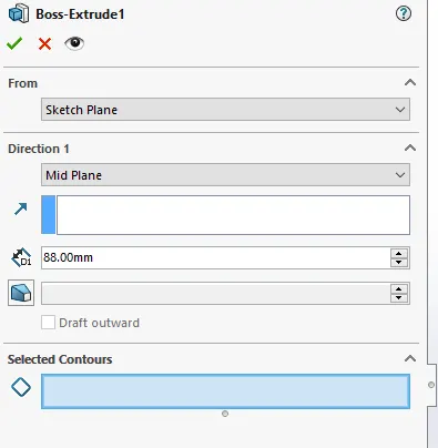
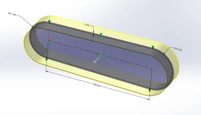
This base feature is often used at the very beginning of a solid part. From a 2D sketch, the shape or countour is extrude to create the third dimension, resulting in a solid model. The extrusion can be made in one direction or two, to specified distance or up to a surface or vertex.
-Fillet

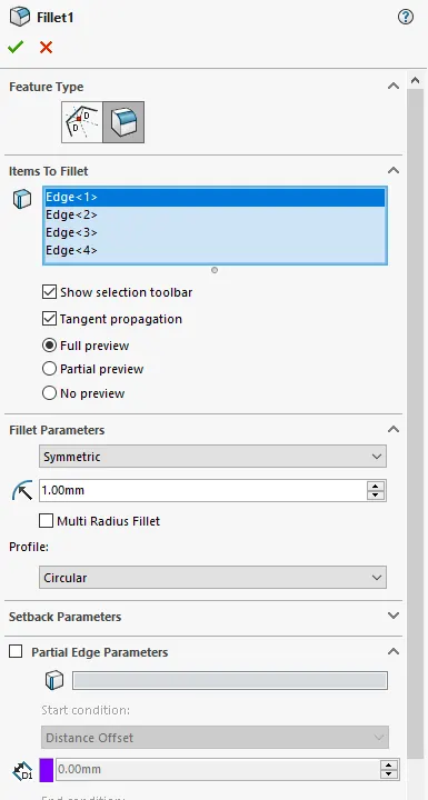
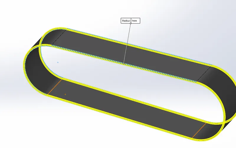
This feature is used to round off edges. It can be used on outside edges and outside edges.
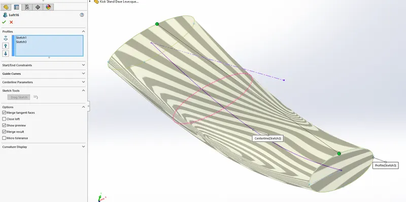
-Loft

The loft feature will create a 3D solid material of a 2d sketch. It will do so by using a start and end sketch that have different shape and make a smooth transisiton between them. The loft in this example is following a guide curve to follow from the start profile to the end profile.
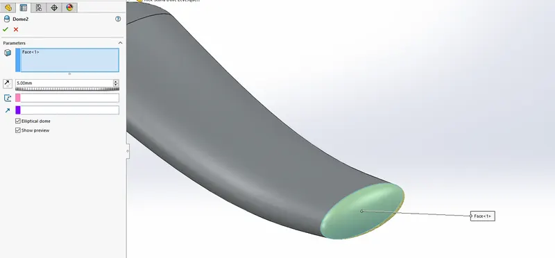
-Dome

The dome feature will create a round smooth convexe face a flat surface.
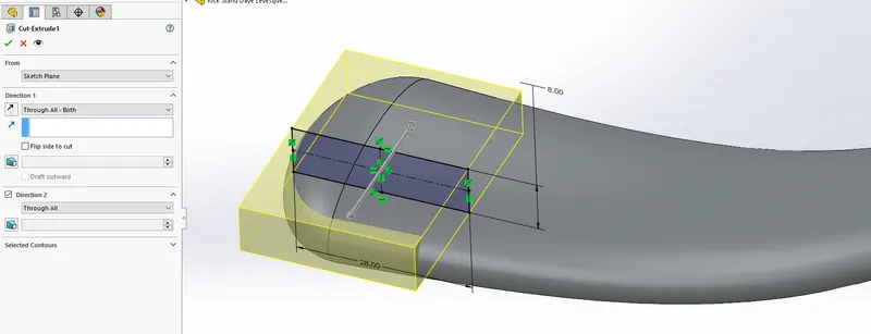
-Cut Extrude

This feature will remove material, by the extrusion of a 2D sketch. The distance to go on the third dimension, can be a specifed distace, in one or two directions, up to a surface and edge or a vertex.
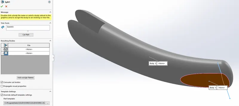
-Split

This feature is used to separate a part using a sketch. There is the option to keep both splitted pieces or to eleminate one to keep only the other one. The user selects which piece to cut or keep.
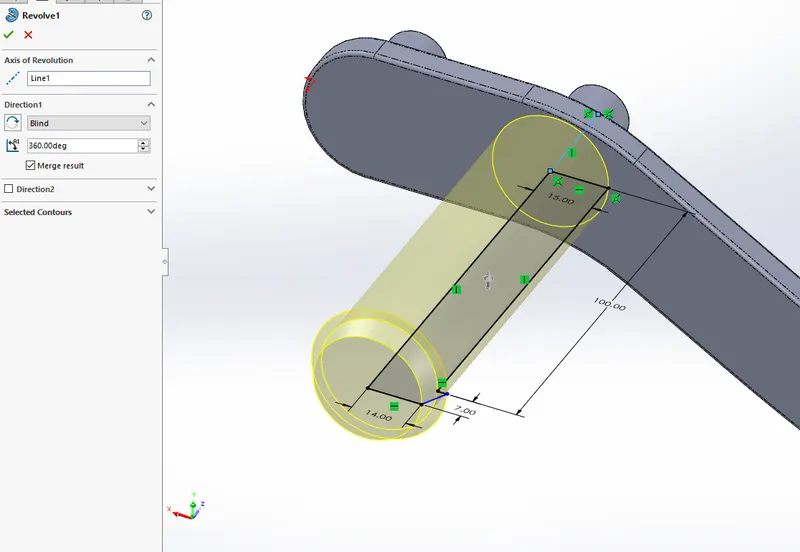
-Revolve

The revolve feature create a solid material addition to a part. Working from a 2D sketch and a reference axis of revolution, it will revolve the profile around the chosen axis. Most of the time, a 360 degree and is used, but nay other angle can be specified.
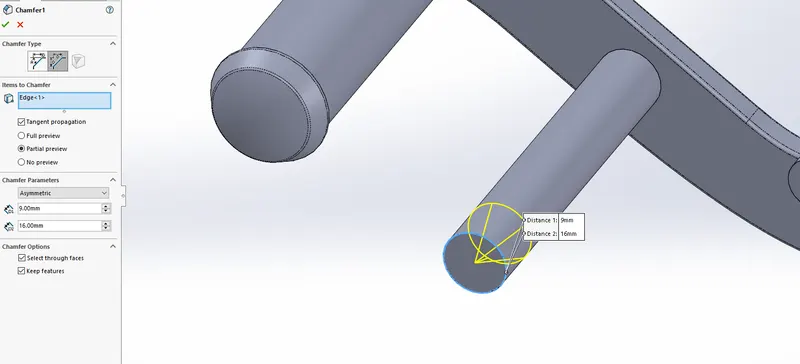
-Chamfer

The chamfer feature is used to cut sharp edges into angled chamfer. It can be used on outside edges and outside edges.
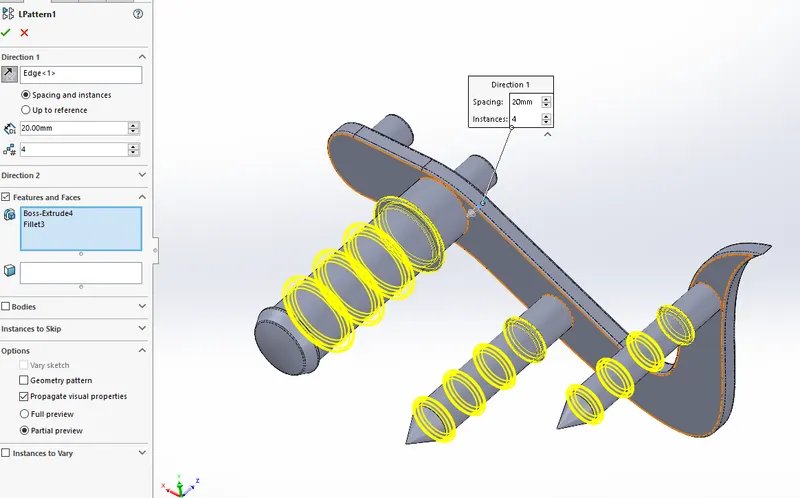
-Linear Pattern

The linear pattern is used to copy previously made features,faces or bodies along a linear path with a specific distance and number of instance. It can go in one or two direction, or up to reference.
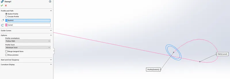
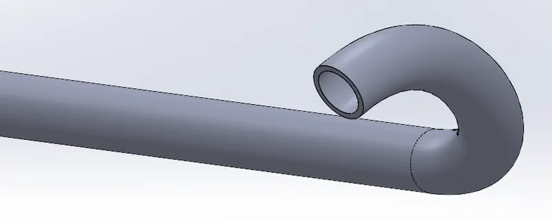
-Sweep

The sweep feature will take a 2D sketch and extrude it along a path. This path is another sketch or a 3D curve. There are options about the profile orientation and how the profile should be twisted, or not, along the path.
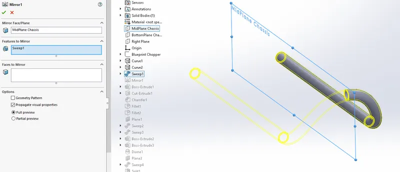
-Mirror

The mirror feature is used in a part to mirror an other feature agains a reference plane or face.
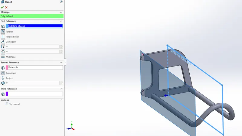
-Plane

Plane is one of the feature from the reference geometry group. It helps the user creating additional on demand reference work plane. By default, a new part or assembly comes with 3 basic work planes. In case the user needs a different plane for the design about to happnen, a new plane can be created. The input required could be
- an existing plane
- an edge
- a face
- a point, vertex
- an axis
Then the possiblities are
- parallel
- perpendicular
- angle
- offset
- midplane
Creating a new reference is a great way to buiild a 3D model that will be easy to process, update, understand and modify.
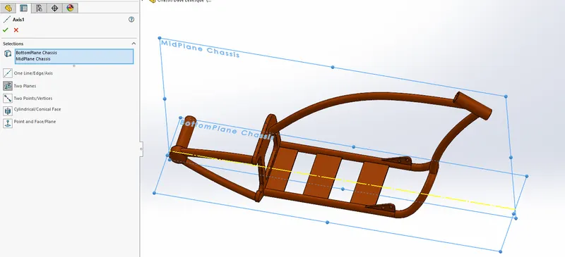
-Axis

Plane is also one of the feature from the reference geometry group. When a reference axis is needed, this feature will alow the addition of an user defined axis. It would be created from
- One line/edge/axis
- the intersection of two planes
- two points/vertices
- a cylindrical or conical face
- the intersection between a pooint and a plane
-Combine

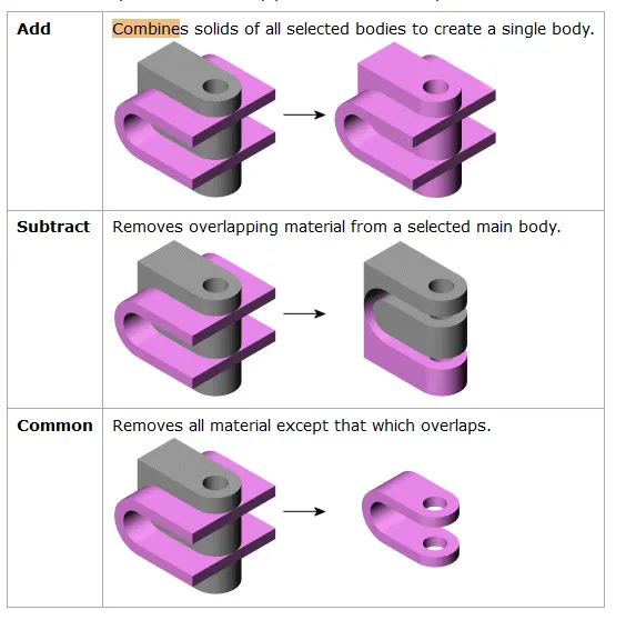
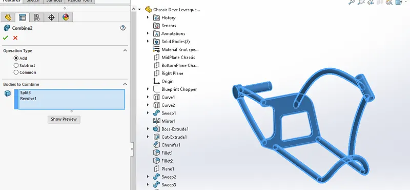
The combine feature can be used when dealing with a multi-body part. The feature will allow to merge, substract or keep what is in common out of different bodies.
-Circular Pattern

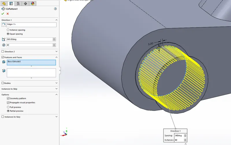
The circular pattern is used to copy features, faces or bodies in a pattern around an axis or along a round edge. The most common use is to created an equal spacing pattern, where we inout the angle to fill and the number of instances.
-Shell

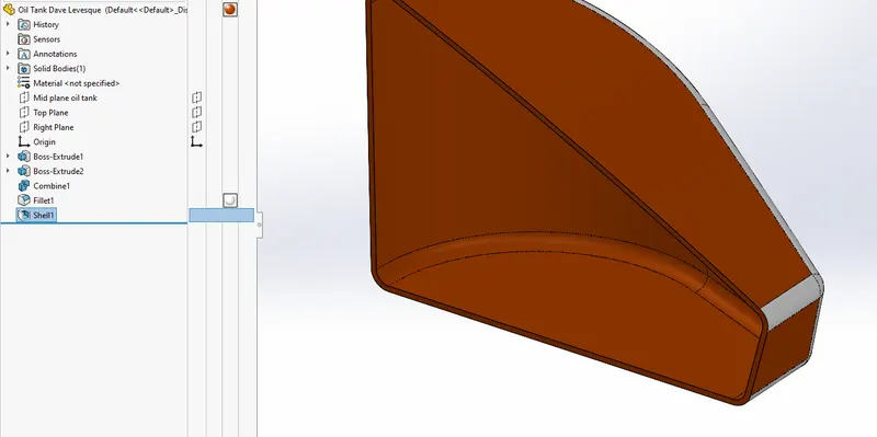
The shell feature will allow the user to create a thin wall solid part out of a solid 3D part. It is sometimes easier to model a part fully solid, and then remove material inside leaving us with a shell. The user canspecify the wall thicknes to remaining and a face to open up, or not.
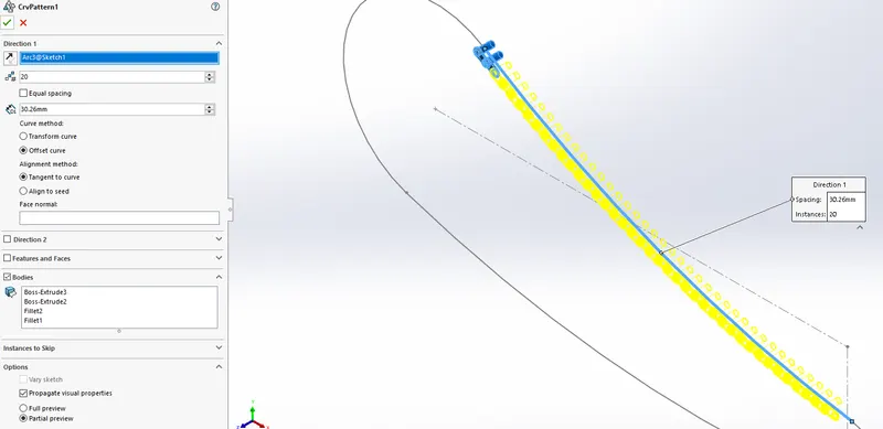
-Curve Driven Pattern

The curve driven pattern feature will copy features, faces or solid bodies following a curve. There is option to have the instances equally spaced or increamented a specific distance.
-Body-Delete-Keep
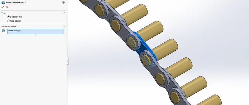
This feature will be used when dealing with a multi body part. It will help the designer to remove extra bodies or keeping only certain ones. The input required is either the bodies to keep or the bodies to remove.
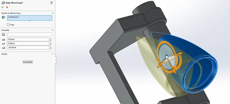
-Body-Move-Copy
This feature will be used when dealing with a multi body part. The use of it iss to move, translate a body. When checking the box copy, the original boy will remain in place.
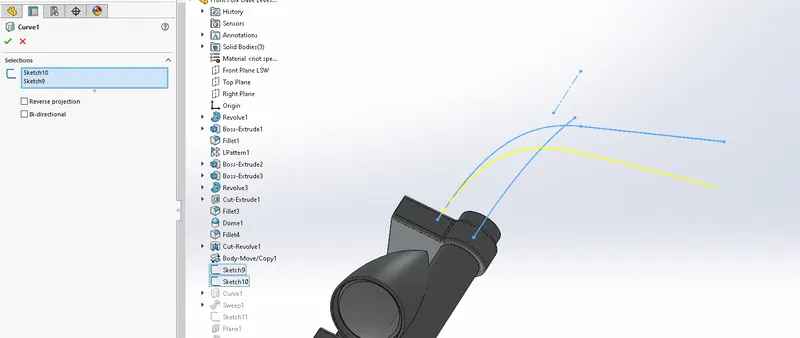
-Curve

The Curve feature will create a 3D curve from the two sketches made on 2D planes. The newly created curved could be used to make a sweep and create a c omplex 3D model.
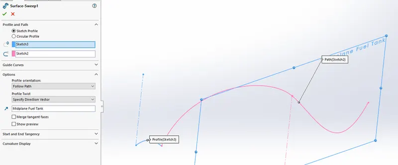
-Surface-Sweep

The surface Sweep feature will help us create a surface from a 2D profil and a sketched path.
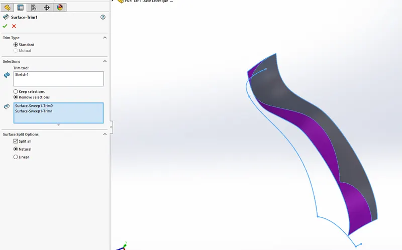
-Surface-Trim
The surface-trim feature will be used when dealing with a surface type of model. It will allow the designer to perform a cut into a complex 3D surface from a 2D sketch.
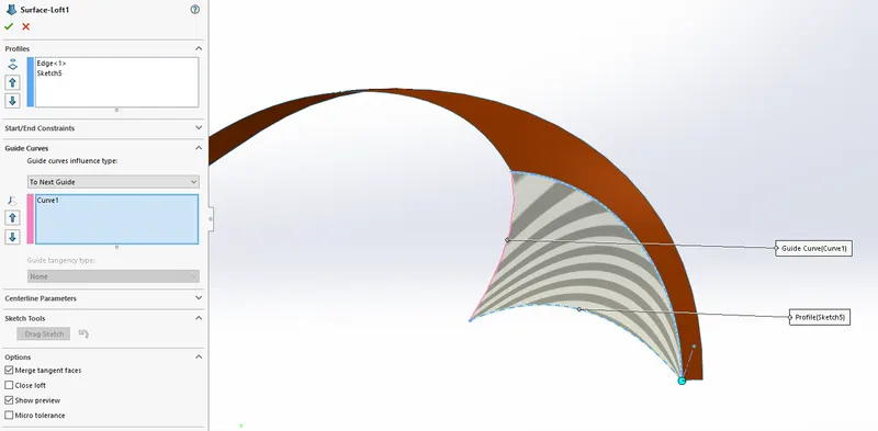
-Surface-Loft

The surface loft feature will help us creating a surface in between to profiles, blending them together. There is the option to include a guide curve to create the loft flowwing the guide cruve creating a #D curved lofted surface.
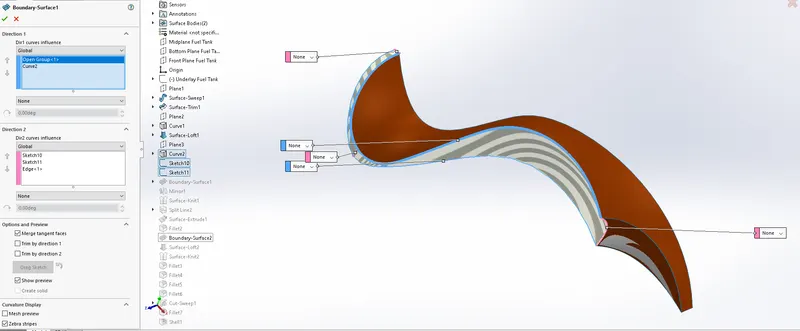
-Boundary-Surface

The boundary surface is a feature to create a surface defined by a combinaison of outside perimeter elements. The coutour is defined by a selecting lines, curves and existing edges.
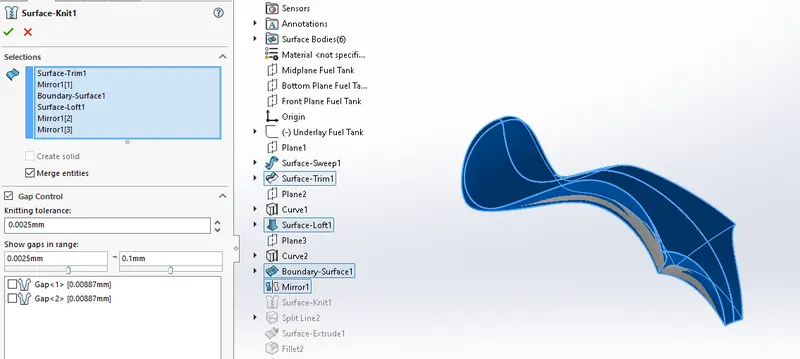
Surface-Knit

Surface Knit is a feature used to combine different surfaces. The srufaces must be adjacents without gaps. There is the option to merger the surfaces or to create a solid from the combined surfaces.
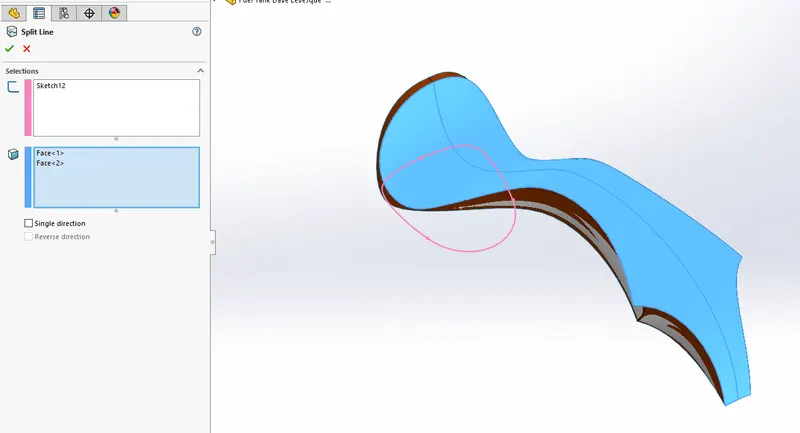
-Split Line

The surface split feature is used to seperate a piece of a surface that is delimited by a sketch.
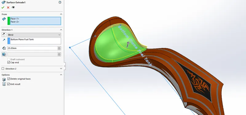
-Surface-Extrude
The surface extrude feature is used to make a surface from a sketch. The lines forming the countour of the 2D sketch are extruded from sketch to a defined distance, or to a surface or any other options similarely o the boss extrusion. There are other otions that be selected, like to cap the end of the newly created surface, deleting the originale surface and knittin the result.
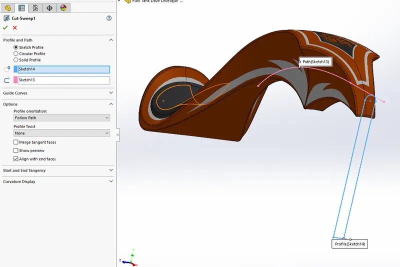
-Cut-Sweep

This feature will make a cut throught the part. Using a profile from a 2D sketch, it will run that cut through following a sweeping path.
Using the blueprint

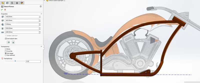
The feature sketch picutre is used to bring a picture, blueprint, drawing and so on in the backgroud of our design space. After creating a new sketch, the feature is created inside that sketch. The size, scale, orientation and position is adjusted so we can draw on top of the picture in a 1 to 1 scale.
Applying the decals

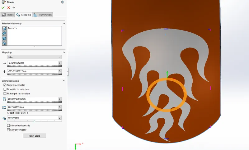
The feature decals is used to apply graphics representing decals or stickers on our parts. By first selecting a graphic file, and then the surface to apply it to, we make this possible. We can adjust parameters like position, rotation and illumination.
Assembly of the components

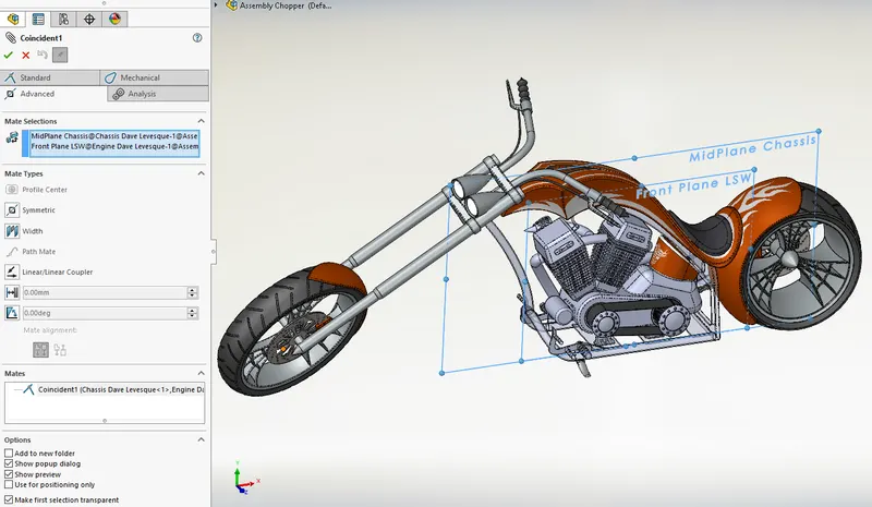
The feature Mate is the main tool to postition, fix, orient and assemble our different part into a solid 3D assembly model. From the selections, planes, edges, faces, axis or vertex the parts can be fixed in the assembly. There are different types of mate offered in the standard mate category
- coincident
- parallel
- perpendicular
- tagent
- concentric
- lock
- distance
- angle
In the advanved mate section, we can find more usefull option of link together the components
- profile center
- symmetric
- width
- path mate
- lnear/linear coupler
- distance
- angle
With the right selections and the right mate options, the chopper was assembled together in a very realistic wa. For example, the front fork is able to turn around its center axis, and the kick stand can be extended or retracted.
Editing of the components in the assembly context
Once all the components assemble, we wanted to check for proper fitment and interfereces. It was found for example, that the kick stand shape was not adquate. The possibility in Soidworks to edit a component within the assembly was great way to make a change on the kickstand while being able to see it in the assembly.
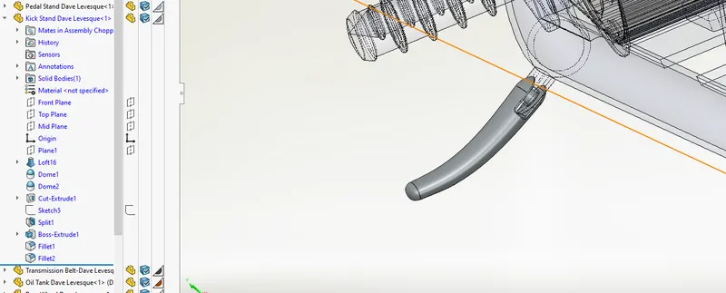
Photo realistic render
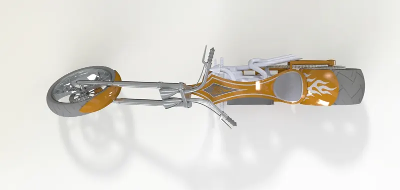
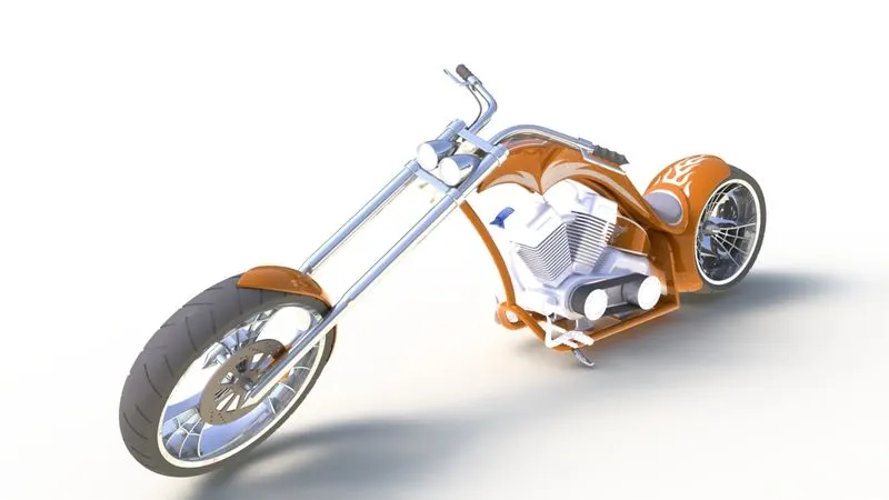
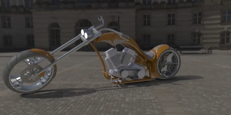
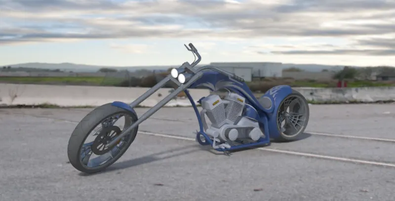
Using the features that Photoview 360 add on is offering us, we learned to setup a scene, lights, camera and background to create a photo quality rendering.
Conclusion
This project has covered a lot, from getting started with Solidworks to making a final render of our prototype. These skill will be really useful moving on in my career.
Project link
https://skill-lync.com/myprojects/edit/61351
References
http://help.solidworks.com/2021/english