Photo Realistic Rendering
MODELING AND RENDERING OF AMERICAN CHOPPER USING SOLIDWORKS
OBJECTIVE :
- To create individual parts of chopper using solidworks.
- To assemble all the individual parts into the chopper.
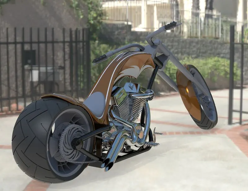
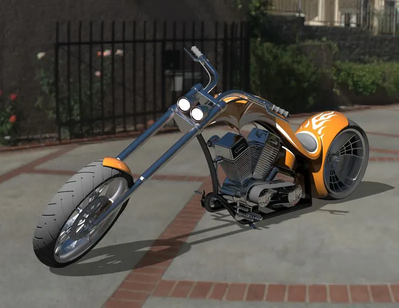
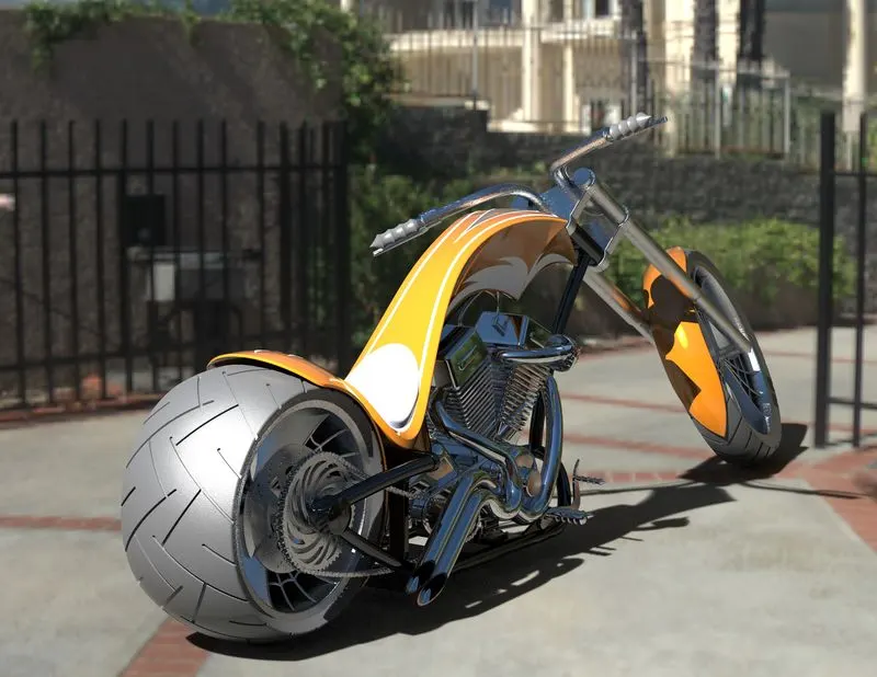
- To create a rendered image using photo view 360.
INTRODUCTION :
SOLIDWORKS is used to develop mechatronics systems from beginning to end. At the initial stage, the software is used for planning, visual ideation, modeling, feasibility assessment, prototyping, and project management. The software is then used for design and building of mechanical, electrical, and software elements.
DESIGN METHODOLOGY/APPROACH :
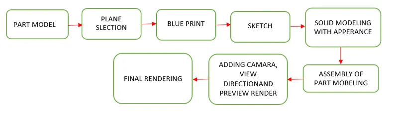
MAJOR TOOL USED IN SOLID WORKS FOR CREATING AMERICAN CHOPPER :
SKETCH :
The sketch is the basis for a 3D model. To create a sketch on any of the default planes (Front Plane, Top Plane, and Right Plane), or a created plane. We can also create a sketch on a flat surface, a spline on a surface, or the face of a solid.
EXTRUDE BOSS/BASS :
An Extruded Boss/Base feature will allow to take a 2D sketch and add thickness to it in the third dimension. It also allows to extrude the surface in both directions and also offset it to required distance.
EXTRUDE CUT :
It is used to remove materials from a solid object in desired patterns and also it can be extruded in both directions.
SPLIT TOOL :
We can create separate part files, and form an assembly from the new parts. We can split one or more solid or surface bodies. To split a surface, the Trimming Surface must extend past the boundaries of the surface to split.
TRIM ENTITIES :
There are two entities:
- Extend entities: It allows the broken lines to intersect each other and this can be done only in 2D sketch.
- Trim entities: It helps to remove unwanted extended line which are intersecting and giving a clean sketch.
SWEPT SURFACE :
Sweep Surfaces are surfaces that are generated from a section curve positioned along a path. Parallel Sweep is defined as a section curve moving along a guide path while maintaining the section curve to be parallel to the guide path.
CHAMFER :
The chamfer tool creates a beveled feature on selected edges, faces, or a vertex.
DYNAMIC MIRROR :
To make the solid body identical to each other this feature is used.
COMBINE :
Combine feature is used to combine two or more solid bodies when intersecting to each other and make it a single body.
FILLETS :
This is to create a curve surface on the profile edges on solid model by selecting the required lines or the face. This fillet also has a feature to select multiple lines which reduce time consumption.
OFFSET :
Offset one or more sketch entities, selected model edges or model faces by specified distance. For e.g. we can offset sketch entities such as splines or arcs, set of model edges, loops and so on. You can offset finite lines, arcs and splines.
REVOLVE :
it is used to create a sketch that contains one or more profiles and a Centre line or an edge to use as the axis around which the feature revolve tools.
DYNAMIC MIRROR :
Dynamic mirror, it is used as you sketch the entities, they are mirrored about the presketched sketch entity.
SHELL :
The shell tool hollows out a part, leaves open the faces you select, and creates thin-walled features on the remaining faces.
LINEAR PATTERN :
It is also same as circular pattern. The feature or the bodies are patterned linearly.
CIRCULAR PATTERN :
Replicate selected parts, faces, or features about an axis or Mate connector (inferred or existing). Create new parts or modify existing parts by adding or removing material, or intersecting parts in its path.
MOVE/COPY BODY :
This feature is used to move/copy the body from one plane to another.
MIRROR :
Mirroring will allow us to “copy” of an existing object, we must choose a plane to mirror parts. In some cases,we may have to create our own plane to have the mirror.
PROJECTED CURVE :
Projected curve is a kind of 3D curve which is projected based on the two different 2D sketches. we can project a sketched curve onto a model face to create a 3D curve. we can also create a 3D curve that represents the intersection of two extruded surfaces generated by creating sketches on two intersecting planes.
SWEEP :
A sweep is a tool that creates a solid, a cut or a surface feature by moving a profile along a path.
COMPOSITE CURVE :
This feature is used to join two curves and make them a single curve.
LOFT SURFACES :
Loft surfaces are surfaces generated by multiple 3D curves or existing edges creating a smooth tangency between the selected curves.
SWEEP SURFACE :
Sweep surfaces are surfaces that are generated from a section curve positioned along a path.
FILL SURFACE :
The Filled Surface feature constructs a surface patch with any number of sides, within a boundary defined by existing model edges, sketches, or curves, including composite curves. we can use this feature to construct a surface to fill a gap in a model.
SURFACE TRIM :
Trim a surface is to create two or more surfaces that intersect at one or more points or create a surface that intersects with a plane or has a sketch on its face.
SURFACE KNIT :
The Knit Surface tool is used to combine two or more faces and surfaces into one.
TOOLS AND FEATURES USED FOR EACH PART :
CHASSIS :
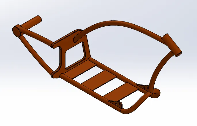
Tools used to create Chasis :
- Sketch.
- Offset.
- Convert Entities.
- Project Curve.
- Trim.
- Sweep.
- Split.
- Revolve.
- Cut Extrude.
- Fillet.
- Combine.
ENGINE :
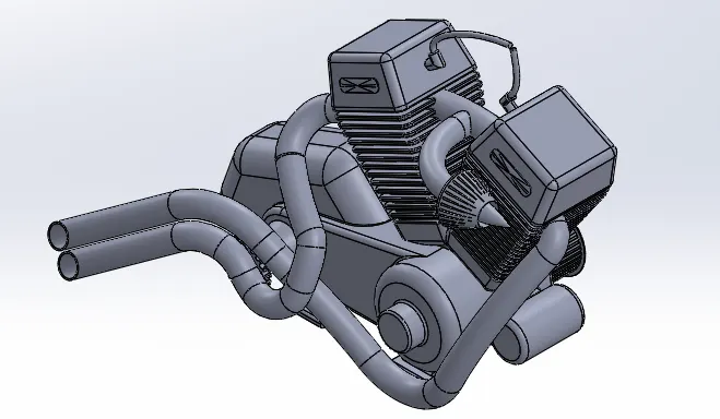
Tools used to create engine :
- Sketch.
- Trim.
- Revolve.
- Boss Extrude.
- Extrude Cut.
- Offset.
- Dome.
- Fillet.
- Projected Curve.
- Composite Curve.
- Sweep.
- Mirror.
- Circular pattern.
- Split.
TRANSMISSION BELT :
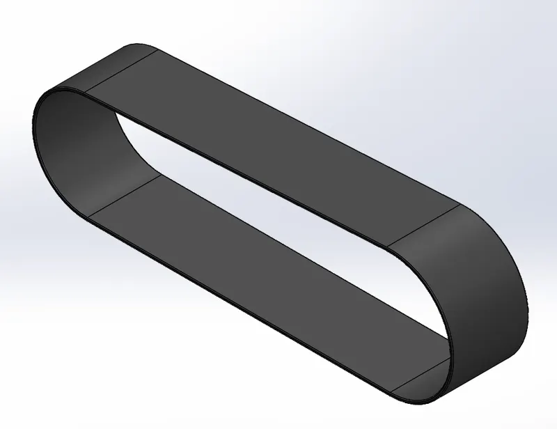
Tools used to create Transmission Belt :
- Sketch.
- Offset.
- Extrude.
- Fillet.
- Appearances.
CHAIN :
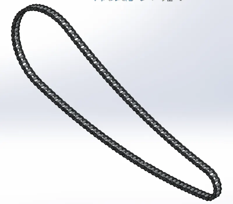
Tools used to create Chain :
- Sketch.
- Trim.
- Fillet.
- Blocks.
- Extrude.
- Patterns.
- Appearances.
OIL TANK :
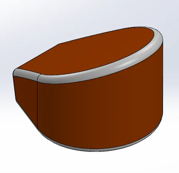
Tools used to create oil tank :
- Sketch.
- Boss Extrude.
- Combine.
- Fillet.
- Shell.
PEDAL :
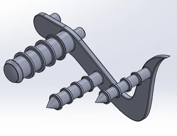
Tools used to create Pedal :
- Sketch.
- Extrude.
- Fillet.
- Linear pattern.
- Dome.
- Chamfer.
REAR FENDOR :
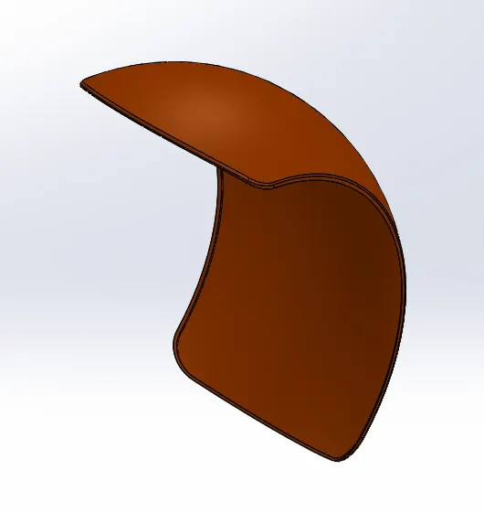
Tools used to model Rear Fender :
- Sketch.
- Offset Entities.
- Trim Entities.
- Revolve.
- Appearances.
REAR TIRE :
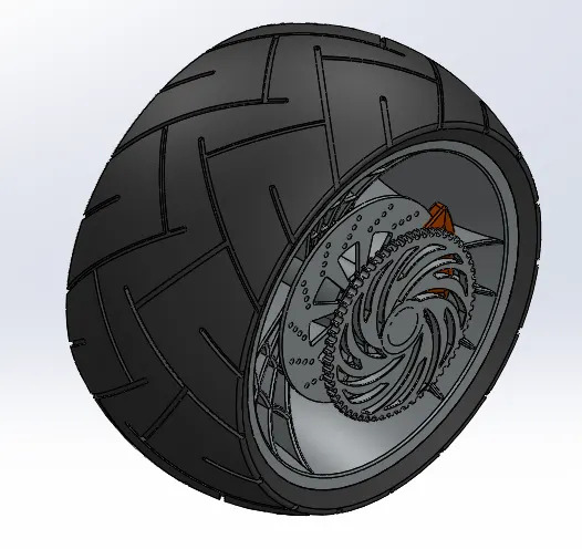
Tools used to create rear wheel :
- Sketch.
- Revolve.
- Trim.
- Sketch fillet.
- Extrude Boss.
- Planes.
- Revolve cut.
- Linear pattern.
- Chamfer.
- Fillet feature.
- Extrude Cut.
- Circular pattern.
FRONT FORK :
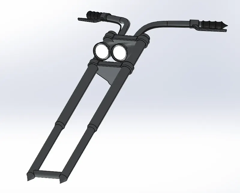
Tools used to create Front Fork :
- Sketch.
- Extrude.
- Trim.
- Revolve.
- Split.
- Move/copy bodies.
- Dome.
- Mirror.
- Combine.
- Projected curve.
- Sweep.
FRONT FENDOR :
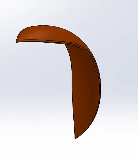
Tools used to create Front fender :
- Sketch.
- Offset entities.
- Trim entities.
- Revolve.
- Dynamic Mirror.
- Split.
- Appearances.
FRONT WHEEL :
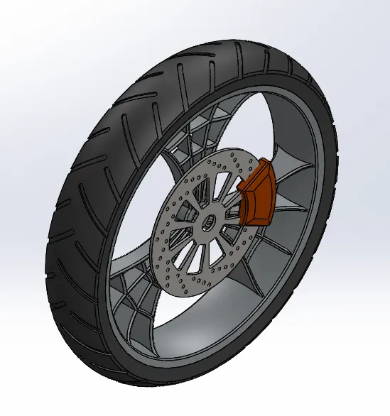
Tools used to create Front Wheel :
- Sketch.
- Revolve.
- Trim.
- Fillet sketch.
- Boss Extrude.
- Revolve Cut.
- Linear Pattern.
- Chamfer.
- Cut Extrude.
- Circular Pattern.
KICK STAND :
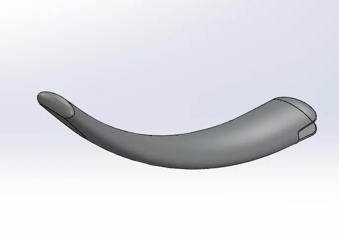
Tools used to create kickstand :
- Sketch.
- Loft.
- Dome.
- Extrude boss.
- Extrude cut.
- Fillet.
- Split.
FUEL TANK :
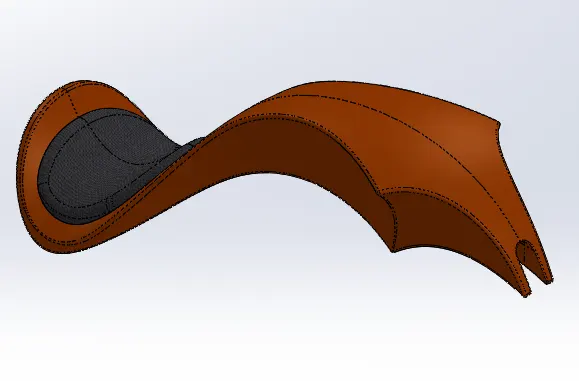
Tools used to create Gas tank :
- Trim.
- Projected curve.
- Sweep surface.
- Loft surface.
- Fill surface.
- Surface Trim.
- Surface Knit.
- Sweep Cut.
- Fillet.
ASSEMBLY OF AMERICAN CHOPPER :
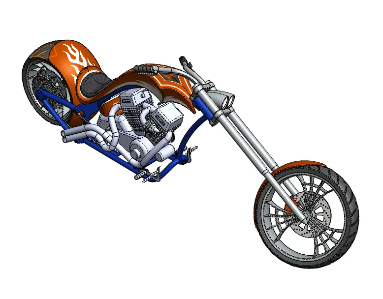
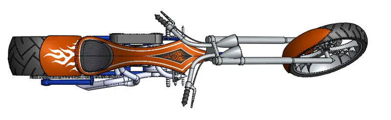
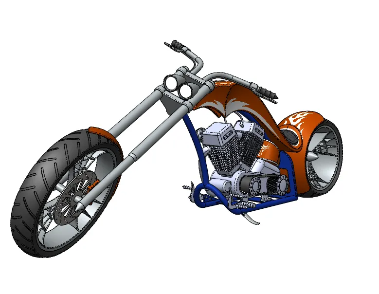
- In the assembly of chopper first the chassis is brought into the assembly part. Then other parts like engine, gas tank, pedal, fuel tank, front fork, front fendor, front tire, rear fendor and the rear tire are brought into the assembly and that has been fixed with the respective plane in the chassis.
- The camera view has been created, so that the chopper will be visible perspectively.
FRONT VIEW :
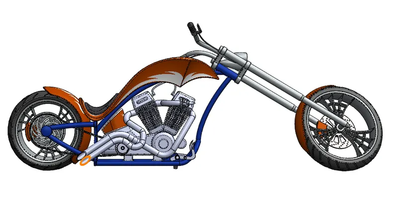
SIDE VIEW :
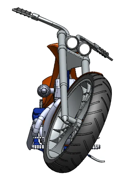
ISOMETRIC VIEW :
TOP VIEW :
CAMERA SETUP VIEW :
RENDERED IMAGES OF AMERICAN CHOPPER :
CONCLUSION :
- The parts of the american chopper are modelled and assembled.
- The realistic image of the chopper is rendered using photo 360 and solidworks visualize.