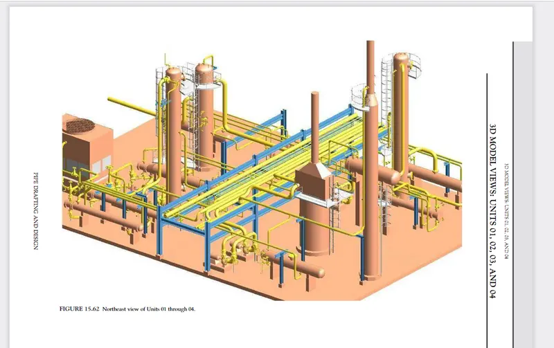
Plant Layout design
Abstract
This report aims to summarize the work done to make a model of a Plant Layout in Invenotor. The inspiration to make this model comes from the keen interest in Plant Engineering.
With this model, the intention was developing studies to concepts of Plant Layout and then apply them using CAD Software.
Content
- Analyzing Pipe flow and Plant Layout
- Sourcing of Components
- Parts Modelling
- Assembly
Plant layout is the physical arrangement of industrial facilities.It involves the allocation of space and the arrangement of equipment in such a manner that overall operating costs are minimized.
Analyzing of Pipe and Plant Layout
Mechanical flow diagrams define the exact sequence in which all mechanical equipment, valves, instrumentation, connections, etc. are to be made on each process pipe routed through the facility.
So By analyzing flow diagram Figured out following things
- Pipe line numbers with direction of commodity flow.
- Pipe specifications and line sizes.
- All mechanical equipment.
- All operating and isolating valves.
- All controlling instrumentation with transmitting devices.
Sourcing of Components
Parts Modelling
ALl parts were designed separately in real size by getting data from appendices.
Assembly
Assembly modeling is the process of creating designs that consist of two or more components assembled at their respective work positions. The components are brought together and assembled in Assembly Design workbench by applying suitable parametric assembly constraints to them. The assembly constraints allow us to restrict the degrees of freedom of components on their respective work positions
For ease of assembly created subassmbly of the pipes.
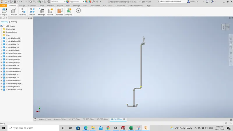
Sub assembly for 44-C30-10 Pipe
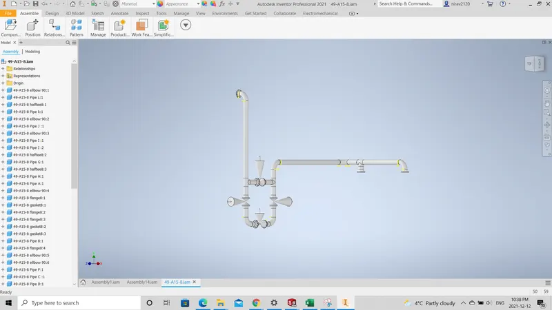
Sub assembly for 49-A15-8 Pipe
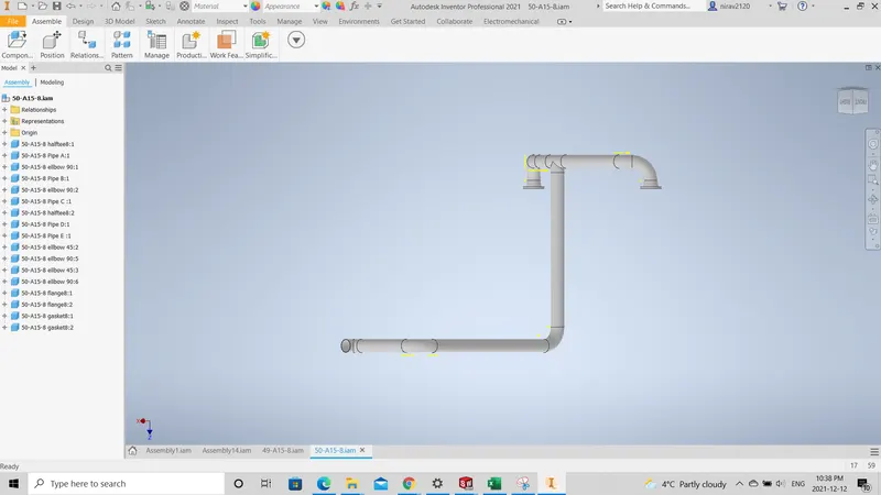
Sub assembly for 50-A15-8 Pipe
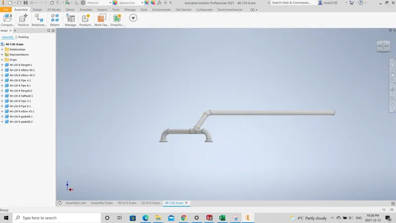
Sub assembly for 48-C30-8 Pipe
Final Assembly
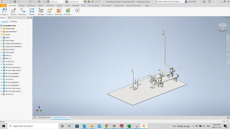
For this Project i did analysis of 1/4 part of the plant layout.