Modeling components of American Chopper in Solidworks and assembling them.
Objective
To model components of American chopper using Solidworks, assembling the components and
rendering them.
Introduction
This project report gives a glance at how I modeled the components of the American chopper
and assembled them after modeling. Moreover, I did a rendering of the components and final
assembly.
Design Methodology
1. Components modeling
2. Assembly
3. Rendering A 2D sketch serves as the foundation for creating a 3D model.
Some of the major Features used for modeling of components are as follows:-
Sketching:-
A 2D sketch serves as the foundation for creating a 3D model.
It's made on plane with two axis. Various line tools, circles, rectangles, splines, and other geom
etric shapes are commonly utilized to make rough sketches.This project made extensive use of tools such as 'Power trim,' 'Trim extend,' and others.
Projected curves:-
Projected curves are used to construct a 3D curve by projecting a sketched curve onto a model
face. Sketches on two intersecting planes can also be used to make it.
Trim:-
On a 2D sketch, trim is used to reduce the extra edges of intersecting lines.
Offset:-
This command is used to add sketch entities by offsetting faces, edges, curves, and other
objects in a specific direction and distance.
Convert entitles :-
Convert chosen model edges or sketch entities to the current sketching plane.
Boss Extrude:-
Extrudes a drawing or selected contours in defined directions to create a solid feature with Boss
Extrude.
Revolved boss:-
Revolves a sketch or selected sketch contours around an axis, resulting in a solid feature.
Swept Boss:-
Creates a solid feature by sweeping a closed profile along an open or closed path.
Extruded Cut:-
It removes material from a 3D object in a specific direction according to the selected profile.
Revolved Cut:-
It removes material from a 3D object around a defined axis according to the selected profile.
Loft:-
The loft feature aids in the creation of complex geometry by allowing for transitions between
various profiles and the usage of guiding curves.
Dome:-
A smooth circular vault forming the outside face of a body or construction is known as a dome.
Fillet:-
a tangent curve that is used to join neighboring faces.
Chamfer:-
A predetermined slanted line is used to link adjacent faces.
Combine:-
It's a tool for combining two or more solid bodies.
Extended surface:-
Extends a surface's selected edge in a specified direction and distance.
Ruled surface:-
It is used to install a ruled surface based on the edges that have been selected.
Offset surface:-
Creates an offset surface by combining one or more faces.
Surface fill:-
Create a surface patch within a defined boundary with surface fill.
Boundary surface:-
Creates a boundary surface in two directions between profiles.
Lofted surface:-
It's used to make a lofted surface between two additional profiles.
Trim surface:-
It's a tool for removing undesired parts of a surface based on a sketch profile or other features.
Shell:-
Shells are used to hollow down a portion, leaving the faces we want open while creating thin walled features on the rest.
Components of American chopper
The major components modeled American chopper are as follows:-
• Transmission Belt
• Kickstand
• Chain
• Rear Fender
• Rear Wheel
• Front Wheel
• Front Fender
• Pedal
• Oil Tank
• Front Fork
• Chassis
• Engine
• Gas Tank
Components modeling
Transmission Belt
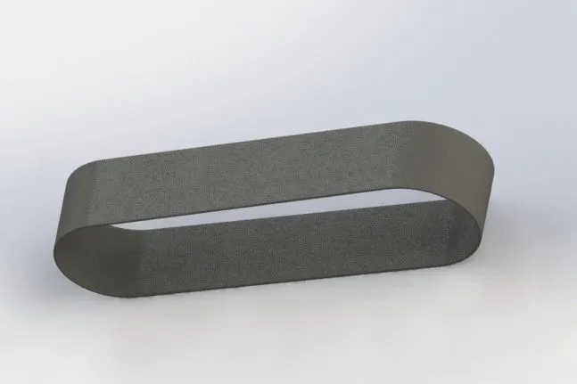
While modeling the transmission belt I got introduced to different sketch tools like
smart dimension,' spline tool, trim tool, circle tool, and numerous line tools like
centerline, Midpoint line, and so on. Also learned to apply different limitations to
sketches, such as tangency, horizontal relation, vertical relation, renaming planes, and
so on. I learned how to use tools like 'Extruded Boss/Base,' 'Fillet,' and others. Finally at
the end learned how to use the 'Appearances' tool to apply various materials.
Kickstand
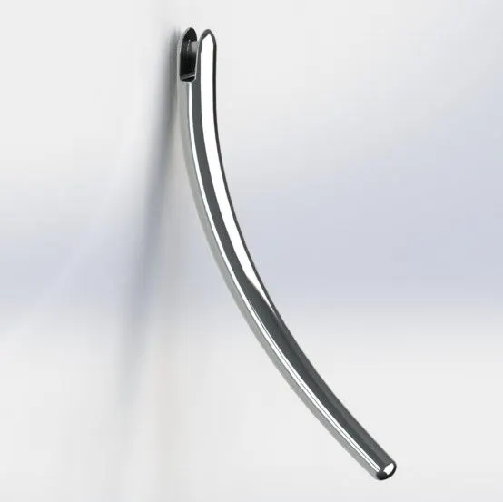
I learned how to use sketch tools like 'ellipse," spline,' and others by modeling this part.
Using 'Lofted Boss/Base,' I learned how to make a loft. The 'Dome' tool was utilized at
the end of the modeling process to generate smooth curved end faces. The 'Extruded
Boss/Base' tool was also used to model a provision for tilting the stand.
Chain
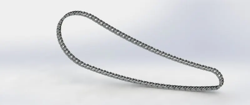
While modeling chain learned how to create and save 'blocks,' which we utilized, later
on, to represent as a component with repeated elements or sections. The pins and
chainplates, for example, were repeated parts in this scenario. Also used the 'curve
driven pattern' tool while modeling.
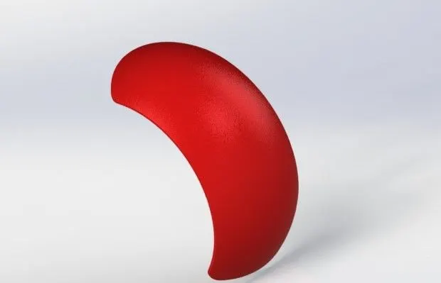
Rear Fender and Front Fender
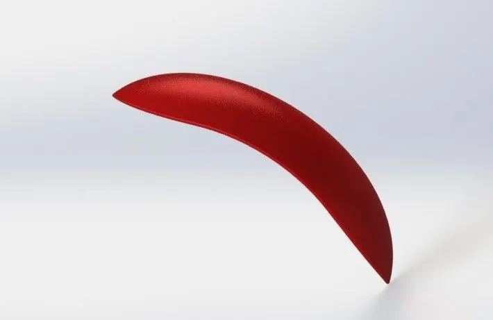
Revolved Boss/Base', 'Split Tool,' and other features were used while modeling the
fender.
The procedure for modeling the chopper's rear fender was nearly identical to that for
modeling the front fender. The shells feature was also utilized in this case.
Rear Wheel and Front Wheel
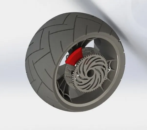
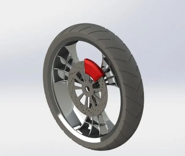
The process for modeling the chopper's rear and front wheels was nearly identical.
However, the breadth of the rear wheel is greater than that of the front wheel. The
road-holding ability of a vehicle is improved by increasing the surface area of contact
between the tire and the road. It also gives the driver more confidence when
negotiating a bend.
While modeling, I modeled the various components of an American chopper's front
wheel. After modeling the rim, rotor, brake caliper, and tire, I gave appropriate
aesthetics by doing assembly of all the components.
Pedal
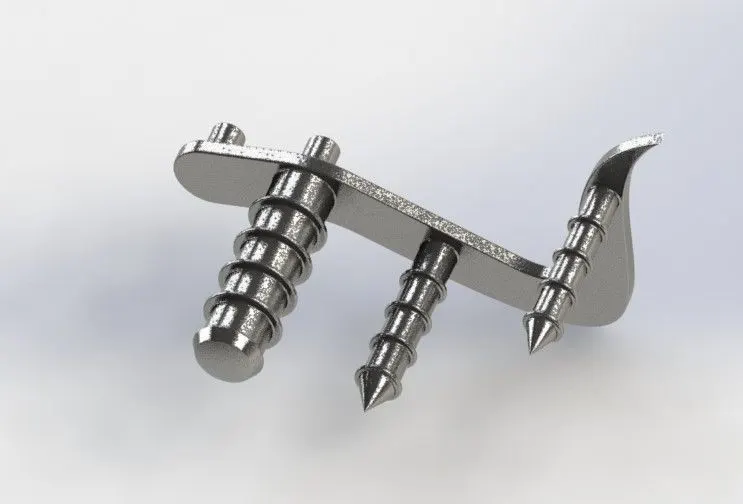
Here, I learned about tools like 'linear pattern,' 'chamfer,' and so on.
Oil Tank
By completing the modeling of an American chopper's oil tank, I became familiar with
techniques like ‘shell,' 'combine,' and giving 'appearances' to particular parts like white
paint for fillets, and so on.
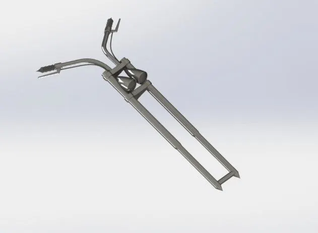
Front Fork
By modeling the motorcycle's handlebars and brake lines, I was able to comprehend the
purpose of Solidworks' 'Projected curve tool.' Modeling the USD (Upside Down) fork,
axle, triple clamps, handlebars, hand grips, brake levers, brake lines, and headlamps
are all part of the assignment. The edges of the headlamp lens were modeled using the
revolved cut' technique.
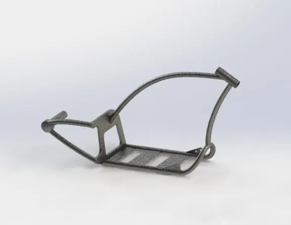
Chassis
The chassis of a motorcycle is referred to as its skeleton. The chassis supports all
components like wheels, suspensions, seats, gasoline tanks, engines, transmission
systems, and so on.
The sweep feature was the major and important feature used while modeling of chassis.
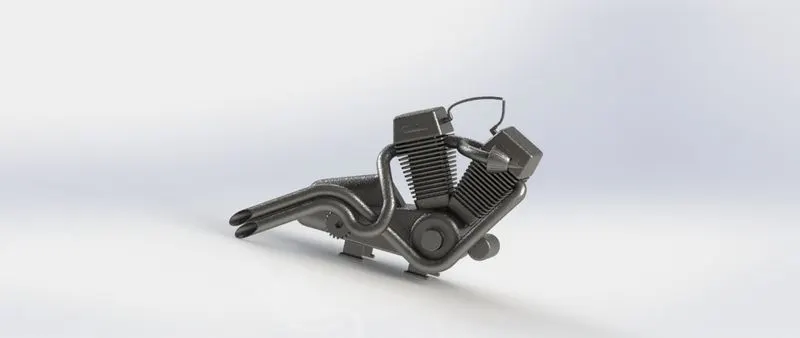
Engine
A V twin engine is a two-cylinder piston engine with a common crankshaft and cylinders
that are placed in a V configuration.
I learned how to make composite curves and use the pierce feature in Solidworks while
modeling the American chopper's engine. These options were mostly used to model
exhaust pipes. For the cooling fins and cylinders, I utilized Cut extrude, Linear pattern,
fillets, and other tools.
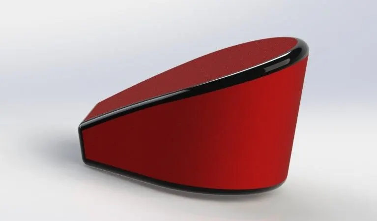
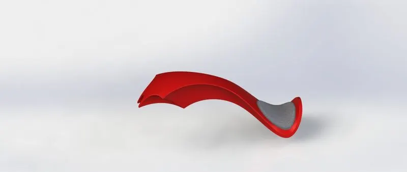
Gas Tank
The gas tank and seat are combined in this design. Because of its curving form, the
spline tool was mostly employed to create the fuel tank and seat. Surface modeling
technologies were used for construction. The tools mostly used to create this model
were swept surface, project curve, lofted surface, knitting tool, shell and many more.
Assembly of components
To assemble the components, each part was individually inserted into assembly file according
to the requirement one by one. Then, for the perfect alignment, required mates were applied
according to the components.
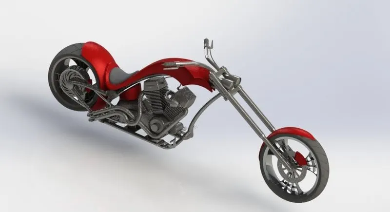
After completing the assembly rendering of final assembly is done.
Rendering
PhotoView 360 was used to render the image. PhotoView 360 is a SolidWorks add-in that
renders SolidWorks models in photo-realistic detail. The rendered image includes all of the
model's appearances, lighting, scene, and decals.
Result
As a result, Solidworks was used to model various components of the American chopper bike
and components were assembled and the assembly model was rendered at the end.