MODELING OF RADIAL ENGINE USING CATIA V5
Abstract
This report aims to summarize the work done to make a model of a radial engine in Catia. The inspiration to make this model comes from the passion for mechanics, the passion for aviation, and the demand for regional cargo transportation presented by developing countries around the world.
With this model, the intention was to develop studies to optimizing the engine through simulations carried out in Catia.
Content
- Parts Modelling
- Assembly Modelling
- Interference Detection
- Kinematic Simulation
- DMU fitting
- Assembly Drawing
1 - Parts Modelling
To make the model, all parts were designed separately in real size and assembled, so that the final assembly simulation could be made to check the feasibility of different scenarios (work conditions).
2 - Assembly Modelling
Assembly modeling is the process of creating designs that consist of two or more components assembled at their respective work positions. The components are brought together and assembled in the Assembly Design workbench by applying suitable parametric assembly constraints to them. The assembly constraints allow us to restrict the degrees of freedom of components on their respective work positions, simulate the forces acting on each component, and verify the behavior of the component that is being analyzed.
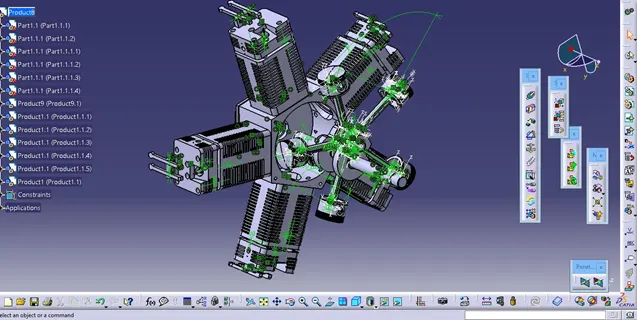
Fig.1 – Radial Engine assembled in Catia.
3 - Interference Detection
After the assembly process, interference and clearance checks between the assembly's components were done to ensure that the components do not clash with one another and that the proper match between the mating parts is retained. The Clash tool is enabled by selecting it from the Space Analysis toolbar's Clash button.
With this procedure, we guarantee that the parts are in their exact working position and the simulation will be done without interference, which could affect the final result of the simulation.
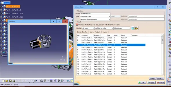
Fig.2 – Interference Detection in Catia.
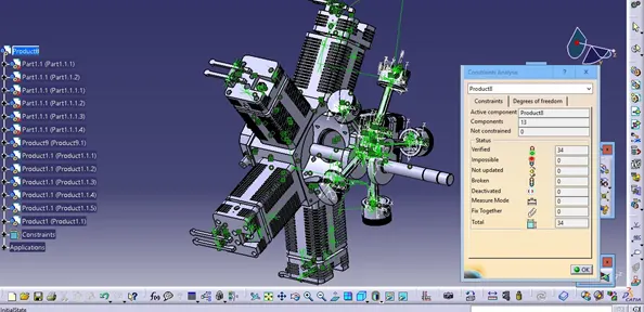
Fig. 3 – Constraint Analysis.
4 - Kinematic Simulation
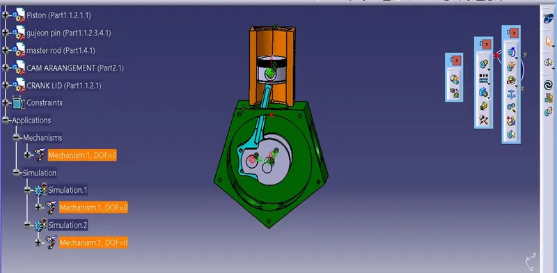
After assembly modeling and interference detection, simulations were carried out to verify that all constraints have been applied correctly and that the movements of the parts reproduce the reality. Simulate component movements help to solve assembly and maintainability problems.
The kinematic simulation consists of steps as follows:
- Make proper assembly delete unnecessary constraints;
- Create joints;
- Convert constraints into a mechanism;
- Create a simulation.
5 - DMU fitting
DMU Fitting Simulator is a module of software that simulates component movements to solve assembly and maintainability problems. It allows the user to describe and model assembly and disassembly processes, allowing for early validation of component assembly and maintenance.
Process of DMU Fitting includes:
- Opening assembly;
- Creating tracks;
- Move a component;
- Record the track;
- Repeat creating tracks for other components;
- Creating a sequence;
- Creating a simulation.
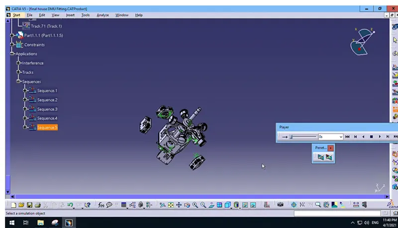
Fig– DMU Fitting (Initial Position)
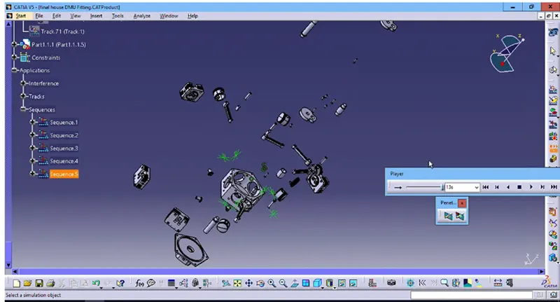
Fig– DMU Fitting (Final Position)
6 – Assembly Drawing
After completing the design of all parts, all simulations, and all finite element analysis, the part is ready to be manufactured. With that, as an example below, a final drawing will be made with all dimensions, tolerances, and assembly sequence.
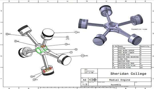
Fig. 7–Assembly Drawing.