Modeling of Boeing 747
Objective
To model components of Boeing 747 using Solidworks, assembling the components and
rendering them.
Introduction
This project report gives a glance at how I modeled the components of the American chopper
and assembled them after modeling. Moreover, I did a rendering of the components and final
assembly.
Design Methodology
- Blue Print Setup
- Components modeling
- Assembly
- Rendering a 3D model.
The Boeing 747 is a wide-body airliner developed by Boeing Commercial Airplanes, the largest variant of the 747. The 747-8 is
widely used for both passenger and freight carrying purposes.
Some of the major Features used for modeling of components are as follows:-
Sketches
The model was created from sketches laid over the top of scaled pictures showing outlines and the main features of the aircraft.
These sketches contained geometries for features to be created. Sketches are created by dimensioning geometries and using
sketch features such as linear/circular patterns. Sketches can also provide constraint entities for other sketches references as
well as feature mates.
Planes
The modeling area of SolidWorks has flat 2D Planes such as the Top, Front, and Right planes by default. Additional Planes were
created and referenced from an existing Plane on which I created sketches or used as a reference for other features. Planes can
also be created using an axis or edges of faces as one or more references.
Axis
Reference axis was used for many features throughout the aircraft's design e.g., positions of which the Landing Gear pivots were
constrained. These axes can be sometimes be referenced directly from the geometry of bodies, this was the case in which the
planes for the sketches of the final features Pitot Tubes were created.
Projected Curve
Some 3D entities were created by a curved line that was the result of an intersection of two projected sketches. This method was
used to produce the guide curves for features such as Lofted Surface for the Fuselage.
Sketch Blocks
Sketch Blocks were used for the Passenger Windows, Doors, and the livery. The Sketch Block tool allowed me to produce multiples
of one sketch by copying it or using a Linear Sketch Pattern. By saving a group of constrained and dimensioned entities together,
the blocks can be inserted into an existing sketch.
Lofted Surface
I used a lofted surface feature to create surfaces such as the Fuselage and the engine's turbine blades. The Lofted Surface
the feature creates a surface by making transitions between multiple sketch profiles and guide curves.
Lofted Boss/Base
I used a Lofted Boss/Base feature to create a solid body of the wings and the horizontal and vertical stabilizers. The Lofted
The surface feature creates a solid body by making transitions between multiple sketch profiles and guide curves.
Extrude Boss/Base
Some solid bodies were created by using an Extruded Boss/Base feature e.g., the Belly Fairing. This feature allowed me to create
a 3D body from a 2D sketch. The Extrude Boss/Base Feature can also be used to create a body that is not perpendicular to the
surface of which it is being extruded, this is achieved by using another reference sketch to define the desired direction, I
used this method to create part of the pitot tubes.
Revolved Boss/Base
I used the Revolved Boss/Base feature tool to produce parts such as the wheels. The Revolved Boss/Base feature creates a solid
body from a selected sketch and extrudes it in circular form around an axis.
Split Line
I used a Split Line feature to cut bodies to a desired size and shape from a projected sketch through the body and consuming
bodies that were no longer desired. The split line feature can also be used to project entities from a sketch onto a surface, I used
this feature to divide a face into multiple separate faces which were sometimes thickened or used to create other features.
e.g., Passenger windows, Doors, and the livery.
Fillet
The Fillet tool is used to create a smooth transition of a dimensioned radius between two or more surfaces. I used this tool to
produce fillets on the edges of faces such as between the Fuselage and the wings. Fillets can also be a variable radius along the
length of the faces, transitioning from a larger radius to a smaller one.
Solidify
The Fuselage was solidified using the Solidify Feature from the Surface Loft. Surface bodies can be made into solid bodies using
this method.
Mirror Tool
The Mirror tool creates a copy of the bodies and sometimes features a selected plane. I used this tool to mirror bodies
such as the fuselage and wings as well as many other features throughout the aircraft's design
Combine
Two or more bodies can be merged into one body. The Fuselage was combined with the Belly Fairing using the Combine feature,
making them one complete solid body
Swept Boss/Base
The Swept Boss/Base feature allowed me to produce a profiled section of a surface that followed the path of a selected contour.
I used the Swept Boss/Base feature to create bodies such as the electrical conductors on the surface of the Nose Cone and
Stabilizer arms of the landing gear.
Chamfer
I used the Chamfer tool to create a beveled edge on the end of the Pitot Tubes. The Chamfer Tool cuts a bevel along an edge or
across a corner. A chamfer can be cut at the desired angle to the adjacent surfaces. In this instance, I used a distance-to-distance chamfer.
Extruded Cut
An Extruded Cut feature was used to remove some of the body of the Pitot Tubes. The Extruded Cut feature removes material
from the part by extruding a sketched profile to desired dimension and path.
Offset Surface
The Offset Surface tool creates a new surface body offset to the desired distance from an existing set of faces or surfaces. This
feature was used to produce an offset surface from the faces of a split line such as the Cockpit Windows. This was achieved by
setting the offset distance to zero.
Thicken
Surfaces can have thickness added to them to produce a solid feature. I used this method to make the solid features like the
Cockpit window frames and the Hatches by thickening one or more of the surfaces to a dimensioned thickness.
Shell Tool
I used the Shell tool to hollow out the fuselage, leaving it with a surface thickness of 50mm. The Shell tool turns solid bodies into
thin-walled features of a desired thickness and leaves face open if selected.
Body-Move/Copy
Some bodies needed to be modeled in a suite of their reference geometry and then moved or copied to their final location, this
was the case with some parts such as the window wipers and Antennas. Bodies can be moved, rotated, and copied to place
using mates or dimensioned translations.
Dome
Details such as lights and wheel hub caps were created by using a Dome. This feature allowed me to produce a curved
the formation, that is shaped like a portion of a sphere.
Linear Pattern
A Linear Pattern can be used to produce multiples of features along a linear path spaced uniformly. I used the Linear Pattern
feature to create multiple instances of features such as the doors, lights, and the details of the landing gear.
Circular Pattern
I used the circular pattern tool to create multiple instances of features spaced uniformly in a circular pattern around an axis.
e.g., Rim bolts on the Wheel Part.
Cut With Surface
Bodies can be cut into sections by an intersecting surface or plane, I used this method to cut the wings flush with the surface of
the Fuselage.
Surface Trim
I used the Surface Trim to cut back the length of the engine's Turbine Blades. The Surface Trim tool trims surfaces were planes,
sketches or surfaces intersect another surface.
Components of Boeing 747
The major components modeled of Boeing 747 are as follows:-
- Fuselage
- Belly Fairing
- Nose Cone
- Pitot Tubes
- Cockpit Windows
- Windshield Wipers
- Passenger Windows
- Doors & Hatches
- Lights & Antennas
- Auxiliary Power Unit (ALU)
- Vertical Stabilizer
- Horizontal Stabilizer
- Wings
- Flaps & Ailerons
- Flap Track Fairings
- Landing Gear Axis
- Landing Gear Hatches Closed
- Landing Gear Hatches Opened
- Wheel
- Nose Gear Base
- Nose Gear Suspension Arm
- Main Gear Base
- Main Gear Suspension Arm
- Engine
- Livery
Different Types of Approaches in Assembly :
1. Bottom-Up Approach
2. Top-Down Approach
ASSEMBLY MODELED IN BOEING 747-8 :
- Nose Gear Assembly
- Main Gear Assembly
- Boeing 747-8 Assembly
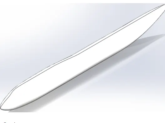
Fuselage :
The Fuselage is an aircraft's main body section. It holds crew, passengers, and cargo. In single-engine aircraft, it will usually contain
an engine, as well, although in some amphibious aircraft the single engine is mounted on a pylon attached to the fuselage, which in
turn is used as a floating hull. The fuselage also serves to position control and stabilization surfaces in specific relationships to lifting
surfaces, which is required for aircraft stability and maneuverability.
Belly Fairing :
Belly Fairing also called a "ventral fairing", is located on the underside of the Fuselage between the main Wings. It can also cover
additional cargo storage or fuel tank.

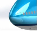
Nose Cone :
Found at the foremost point of an aircraft, a nose cone must be aerodynamic in order to reduce drag on a plane. On most
commercial and military aircraft, the nose cone also houses radar and other instruments that might be used to detect
meteorological phenomena, track enemy aircraft, or transmit communication signals.
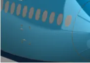
Pitot Tubes :
Pitot tubes are also known as pitot probes. The pitot tube is a flow measurement device used to measure fluid flow velocity. Pitot tube is
widely used to determine the airspeed of the aircraft.
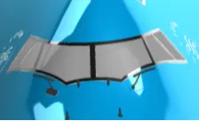
Cockpit Windows :
A cockpit or flight deck is the area, usually near the front of an aircraft or spacecraft, from which a pilot controls the aircraft.
Passenger Windows :
The main thing to know in the aircraft cabin windows are not made of glass, but with something called “stretched acrylic”.
Lights & Antennas :
There are 2 lights and 3 antennas as created in the Boeing 747-8 mode. The lights are on the backside of the cockpit. The two
antennas are in the top of the fuselage and one the beneath of the fuselage.
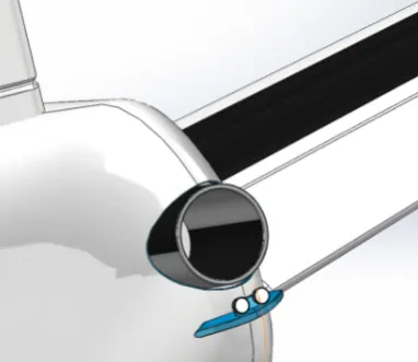
Auxiliary Power Unit (APU) :
An auxiliary power unit (APU) is a device on a vehicle that provides energy for functions other than propulsion. They are commonly
found on large aircraft and naval ships as well as some large land vehicles.
Stabilizer :
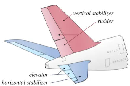
The stabilizer's job is to provide stability for the aircraft, to keep it flying straight.
The vertical stabilizer keeps the nose of the plane from swinging from side to side, which is called yaw.
The horizontal stabilizer prevents an up-and-down motion of the nose, which is called pitch.
Engine :
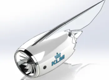
An aircraft engine often referred to as an aero engine, is the power component of an aircraft Air propulsion system. Most aircraft
engines are either piston engines or gas turbines, although in recent years many small UAVs have used electric motors.
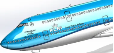
Livery :
An aircraft livery is a set of comprehensive insignia comprising color, graphic, and typographical identifiers which operators (airlines,
governments, air forces, and occasionally private and corporate owners) apply to their aircraft.
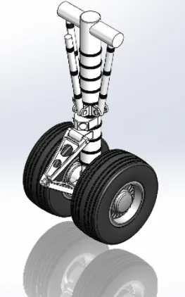
Nose Gear Assembly :
Nose gear has parts like Nose Gear base, Suspension Arms, and Wheels.
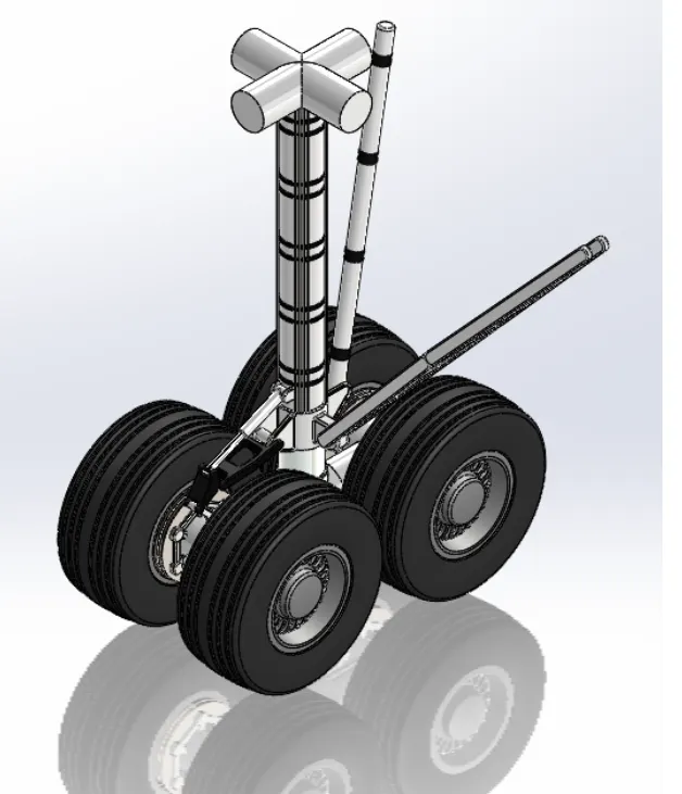
Main Gear Assembly :
The Main Gear Assembly consists of the main gear base, two main gear suspension arms, and four wheels.
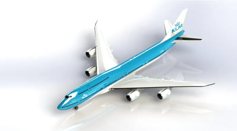
Boeing 747-8 Assembly :
After completing the livery part the main body (Fuselage with all parts) is inserted into the assembly environment. Then the engine
is inserted into the assembly.
Conclusion :
In this project, the various parts of the Boeing 747-8 were modeled with the different Environments Surface modeling, Solid Modeling
and Assembly available in the Solidworks.
The Assembly of the Boeing 747-8 is rendered with Photoview 360 and Solidworks Visualize to create a realistic view of the model with the
environment.