Photo Realistic Rendering
AIM & OBJECTIVE....
- To create American Chopper in Solidworks using various types of sketches and feature tools.
- To assemble different model parts and create a chopper.
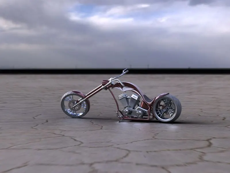
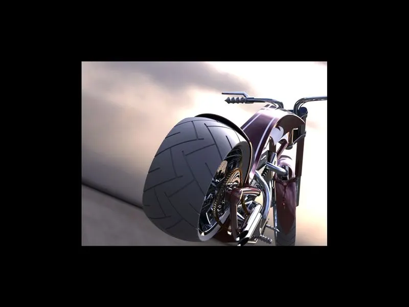
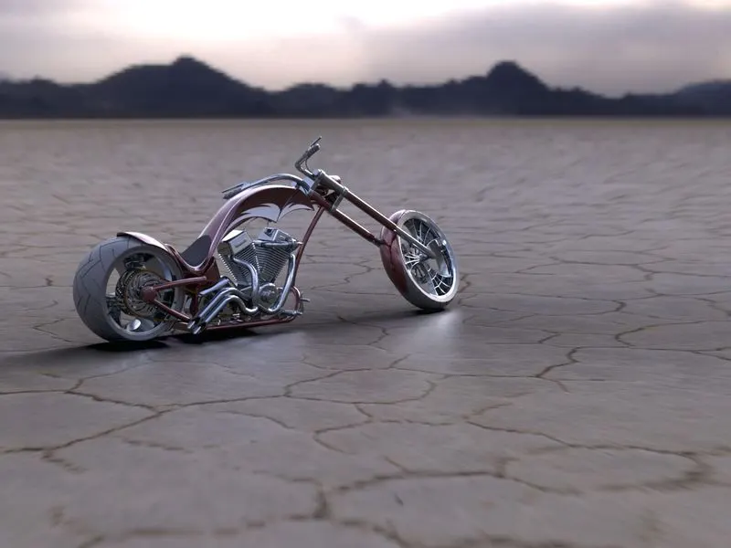
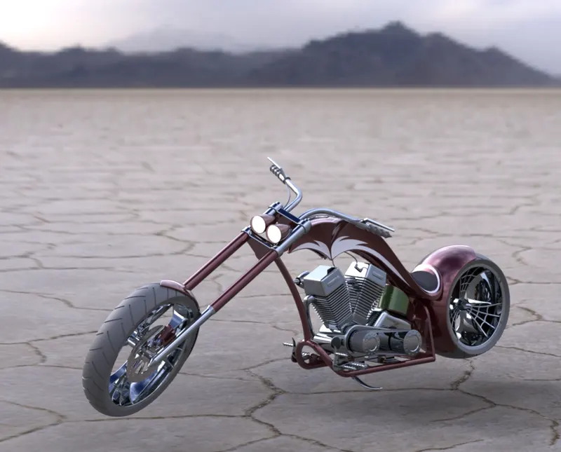
- To create photo realistic images using Solidworks visualize
INTRODUCTION....
the choppre was modelled using part modelling once all the parts were modelled seperately then they are assembled to create the chopper. it consists of following parts,
- chain
- chassie
- engine
- front fender
- front wheel
- front fork
- fuel tank
- kick-stand
- oil tank
- pedal
- rear fender
- rear wheel
- transmission belt
PART MODELLING....
Generally PART modeling means to create a virtual prototype of an object. It can be used for different purposes. Consider the engine of a car / bike. ... Each part can be modeled separately and then can be assembled together to achieve the final form of the engine. This type of modeling is called part modeling
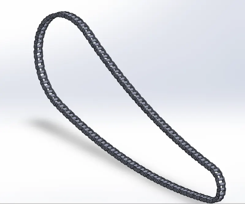
CHAIN....
Motorcycle chains are part of the drive train to transmit the motor power to the back wheel. Properly lubricated chains can reach an efficiency of 98% or greater in the transmission. Unlubricated chains will significantly decrease performance and increase chain and sprocket wear.
Commands used....
Following are the commands used to model the parts.
- 2D-sketch
- Fillet
- Smart dimensions
- Extrude boss /base
- Appreance
Image of the model part....
TRANSMISSION BELT....
Belts are mechanical elements used for power transmission without phase shift. They are loops of flexible materials used to mechanically connect several rotating shafts, most often parallel. Belts can be used as a transmission element, to efficiently transmit power or movement.
Commands used....
Following are the commands used to model the parts.
- 2D-sketch
- Fillet
- Smart dimensions
- Extrude boss /base
- Appreance
- Curve driven pattern
- Mirror feature
- Body delete/keep
Image of the model part....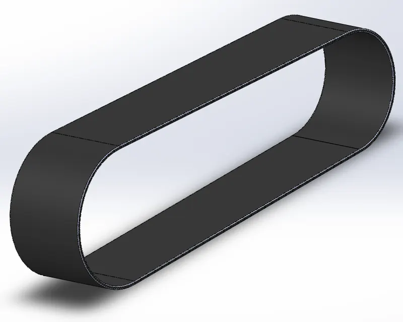
FENDERS....
Fender is the term for the part of an automobile,motorcycle or other vehicle body that frames a wheel well. Its primary purpose is to prevent sand, mud, rocks, liquids, and other road spray from being thrown into the air by the rotating tire. Fenders are typically rigid and can be damaged by contact with the road surface.
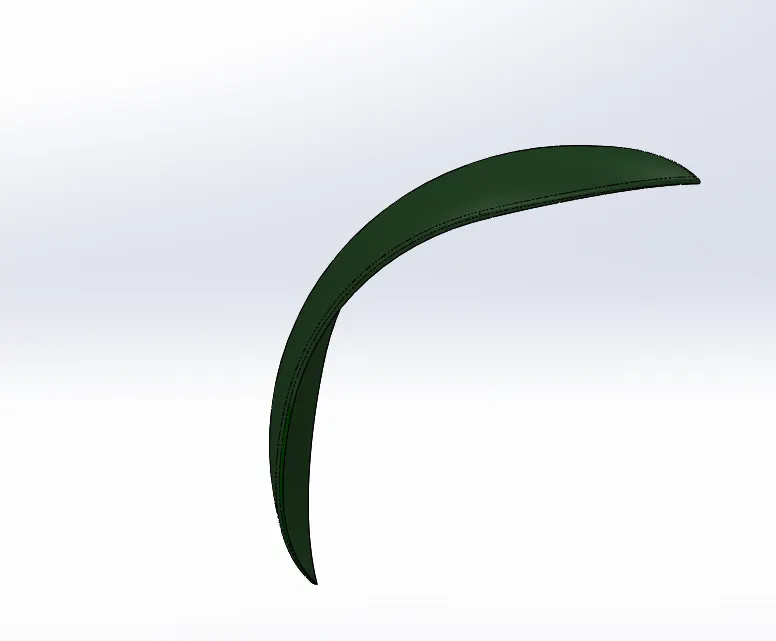
Front Fenders....
It is for the front wheel.
Commands used....
Following are the commands used to model the parts.
- 2D-sketch
- Fillet
- Smart dimensions
- Extrude boss /base
- Appreance
- Split
- Revolve
Image of the model part....
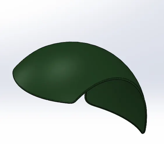
Rear Fenders....
it is for the rear wheel.
Commands used....
Following are the commands used to model the parts.
- 2D-sketch
- Fillet
- Smart dimensions
- Extrude boss /base
- Appreance
- Split
- Revolve
Image of the model part....
KICK-STAND...
A kickstand is a device on a bicycle or motorcycle that allows the bike to be kept upright without leaning against another object or the aid of a person. A kickstand is usually a piece of metal that flips down from the frame and makes contact with the ground.
Commands used....
Following are the commands used to model the parts.
- 2D-sketch
- Fillet
- Smart dimensions
- Extrude boss /base
- Loft boss /base
- Extrude cut
- Dome
Image of the model part.... 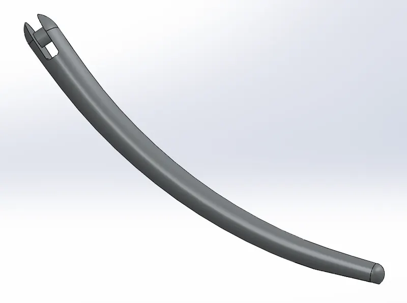
PEDAL....
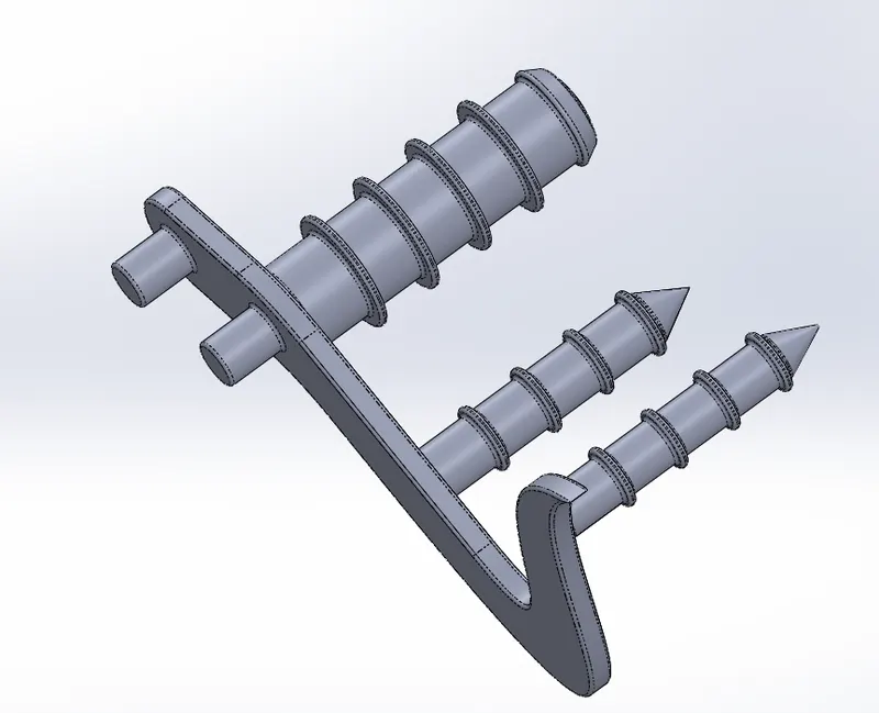
A foot-operated lever used to control certain mechanisms, as automobiles.
Commands used....
Following are the commands used to model the parts.
- 2D-sketch
- Fillet
- Smart dimensions
- Extrude boss /base
- Revolve
- Chamfer
- Dome
- Linear pattern
Image of the model part....
OIL TANK....
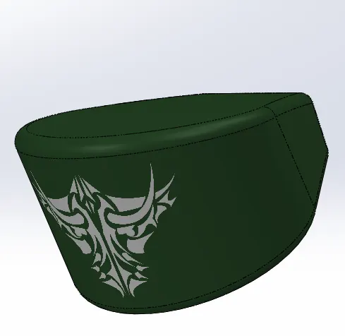
It is used for storing oil. oil tank also comprises of decals.
Commands used....
Following are the commands used to model the parts.
- 2D-sketch
- Fillet
- Smart dimensions
- Extrude boss /base
- Combine
- Chamfer
- Shell
Image of the model part....
WHEELS
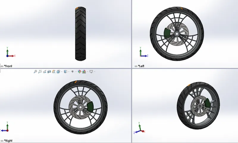
A circular object that revolves on an axle and is fixed below a vehicle or other object to enable it to move easily over the ground.
FRONT WHEEL....
It is at the front of the vehicle. it consists of these parts.
- Rim
- Disk brake
- Tyre
- Caliper
Commands used....
Following are the commands used to model the parts.
- 2D-sketch
- Fillet
- Smart dimensions
- Extrude boss /base
- Combine
- Chamfer
- Extrude cut
- Revolved cut
- Combine
- Circular pattern
- Mirror entities
- Appearence
Image of the model part....
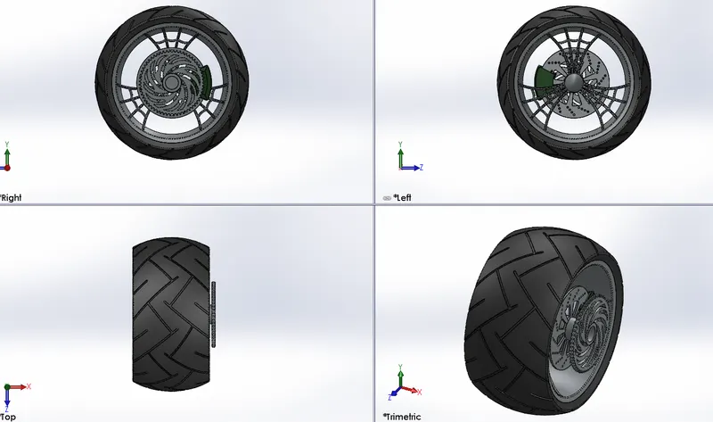
REAR WHEEL ....
it is for the rear of the vehicle. These consists of these parts.
- Rim
- Disk brake
- Tyre
- Caliper
Commands used....
Following are the commands used to model the parts.
- 2D-sketch
- Fillet
- Smart dimensions
- Extrude boss /base
- Combine
- Chamfer
- Extrude cut
- Revolved cut
- Combine
- Circular pattern
- Mirror entities
- Appearence
Image of the model part....
FRONT FORK
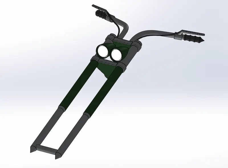
A fork typically consists of two blades which are joined at the top by a fork crown. The crown is often at the front. Most suspension forks have an arch connecting the two side of the lowers the part connected to the axle.
Commands used....
Following are the commands used to model the parts.
- 2D-sketch
- Fillet
- Smart dimensions
- Extrude boss /base
- Combine
- Chamfer
- Extrude cut
- Revolved cut
- Combine
- Circular pattern
- Mirror entities
- Appearence
- projected curve
- Reference plane
- Swept boss / base
Image of the model part....
FUEL TANK....
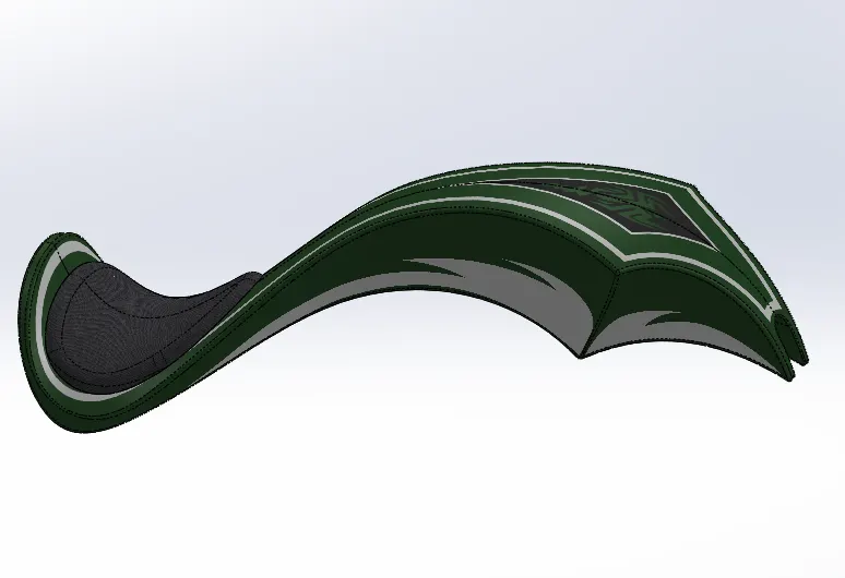
A fuel tank (also called a petrol tank or gas tank) is a safe container forflammable fluids. Though any storage tank for fuel may be so called, the term is typically applied to part of an engine system in which the fuel is stored and propelled fuel pump or released (pressurized gas) into an engine.
Commands used....
Following are the commands used to model the parts.
- 2D-sketch
- Fillet
- Smart dimensions
- Extrude boss /base
- Combine
- Chamfer
- Extrude cut
- Revolved cut
- Combine
- Circular pattern
- Mirror entities
- Appearence
- Projected curve
- Reference plane
- Loft surface
- Knit surface
- Surface trim
- Split surface
Image of the model part....
ENGINE....
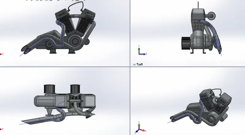
engine is a machine or instrument that uses energy to create mechanical power, or a locomotive on a train. ... Any machine that uses energy to develop mechanical power; esp., a machine for transmitting motion to some other machine.
Commands used....
Following are the commands used to model the parts.
- 2D-sketch
- Fillet
- Smart dimensions
- Extrude boss /base
- Combine
- Chamfer
- Fillet
- Extrude cut
- Revolved cut
- Combine
- Circular pattern
- Linear pattern
- Mirror entities
- Appearence
- Projected curve
- Composit curve
- Reference plane
- swept boss / base
Image of the model part....
CHASSIS
chassis is a vehicle frame, the underpart of a motor vehicle, on which the body is mounted; if the running gear such as wheels and transmission, and sometimes even the driver's seat, are included, then the assembly is described as a rolling chassis.
Commands used....
Following are the commands used to model the parts.
- 2D-sketch
- Fillet
- Smart dimensions
- Extrude boss /base
- Combine
- Chamfer
- Fillet
- Extrude cut
- Revolved cut
- Combine
- Mirror entities
- Appearence
- Projected curve
- Composit curve
- Reference plane
- swept boss / base
Image of the model part....
ASSEMBLY....
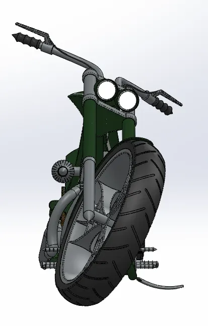
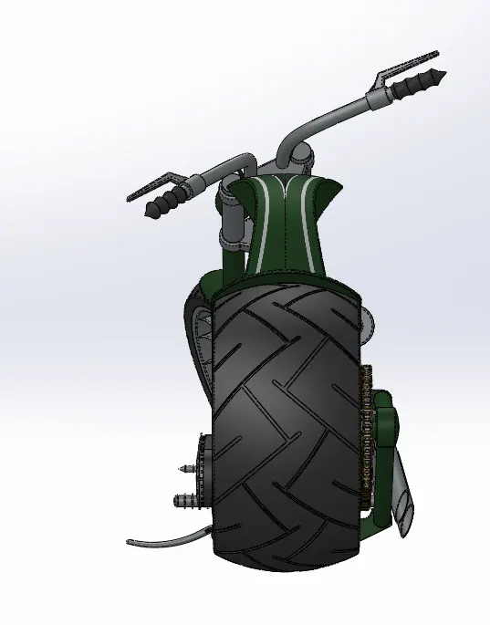
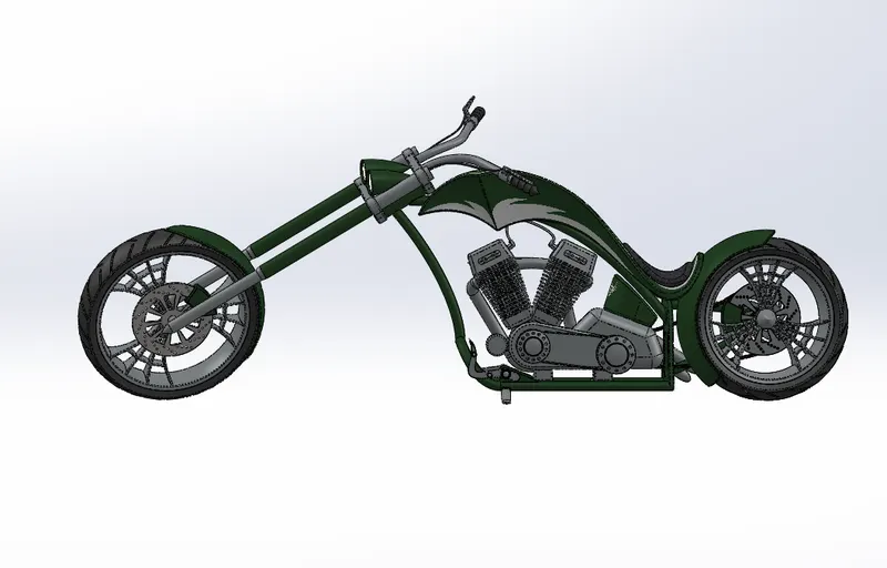
All the modelled parts were inserted one by one in the assembly work bench. all the parts were inserted randomly and given mates manually with respect to chassie, all the parts move with respective to chassie only, when the chassie floats.
Images of the assembly....
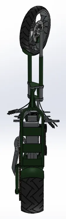
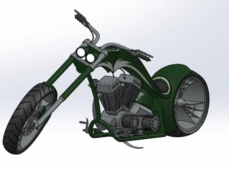
Following are the different views of chopper assembly in different views.
Front view....
Back view....
Right side view....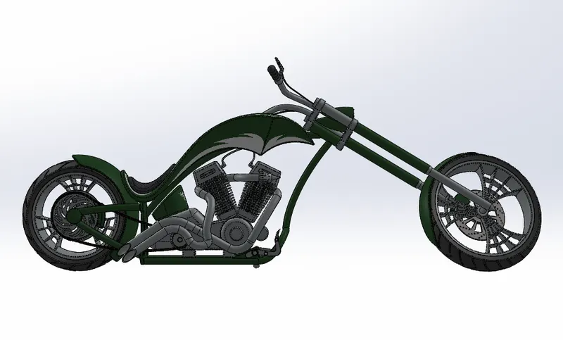
Left side view ....
Top view....
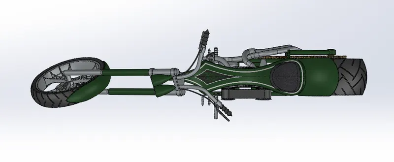
Bottom view....
Isometric view....
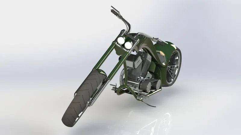
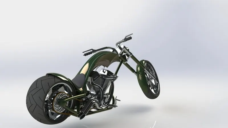
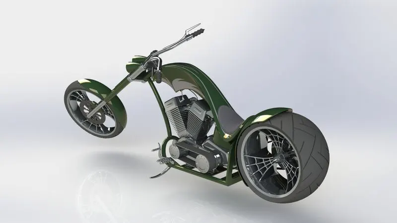
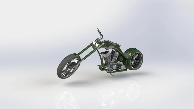
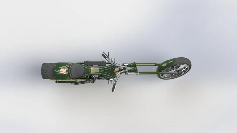
PHOTOREALISTIC RENDERED IMAGES OF AMERICAN CHOPPER .....
CONCLUSION....
ALL the parts of the american chopper were modelled and assembly was created using solidworks and the photorealistic renders were created using solidworks visualize.