Photo Realistic Rendering
MODELING OF AN AMERICAN CHOPPER
OBJECTIVE
To model an American Chopper using Solid Works 2019 by modeling each part separately and assembling it together to form a 3d model. Then Solid Works Visualize was used in order to obtain the realistic images of the American Chopper Model.
INTRODUCTION
Modeling of an American Chopper is one of the project of Ultimate Solid Works Course. In this project there about 13 individual components starting from kick stand, Pedal, Front Fender, Rear Fender, Front Wheel, Rear Wheel, Chassis, Engine, Transmission Belt, Chain, Oil tank and Gas Tank. All the above mentioned part models are modeled individually and assembled together to get the American Chopper Model. And then the Decals and other render textures like adding camera, lights and views where done in the Photo View 360. Then the final render was done. Followed by which is the realistic render was done using Solid Works Visualize with different Environment and backgrounds to obtain the 3d realistic Render of the Chopper. Now let us discuss about the Chopper Assembly in detail.
DESCRIPTION
As Discussed above the individual part models are designed and let us have brief note of it below.
- KICK STAND
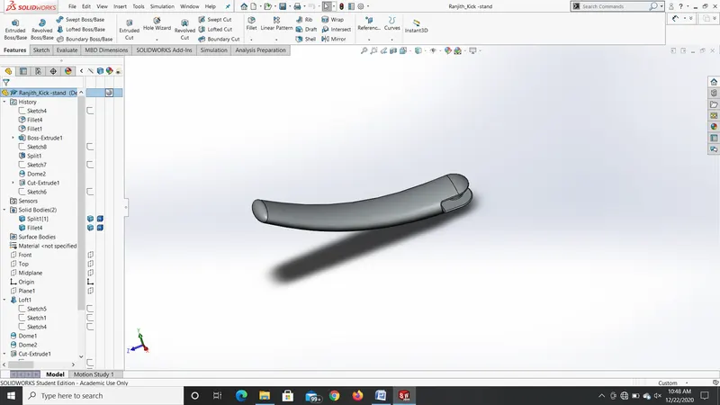
The kick was the first designed model. Initially the shape was roughly drawn using line diagram and then Lofted boss/base feature was use to obtain the initial shape of the kick stand. Them elliptical Dome was drawn at the edges of the kick stand using the Dome Feature. Then Boss extrude and extruded cut option was used to mount the kick stand with the chassis. Then Split option was used to have a smooth landing surface to land the chopper on the floor. Then some Fillets were added to the inside and the outside edges of the kick stand. Then the some appearances were made to the kick stand. The material chosen was Metal - Chromium Plate. The part diagram of the kick stand is shown below.
- TRANSMISSION BELT
The transmission belt is the next component modeled. The transmission belt was initially modeling using line diagram and some three point arcs to obtain the shape of the transmission belt. Then Offset Entities option was used and then the belt was extruded to obtain the shape of the belt. Then appearance of Matte Rubber was used to define the material of the belt. The image of the Transmission Belt is shown below.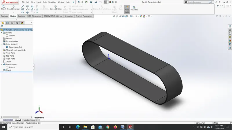 NT 3. FRONT FENDER
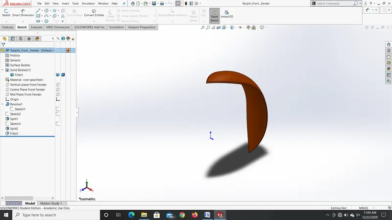
Then the Front Fender is modeled. Initially the shape of the fender was drawn using line diagram and then it is revolved by the center axis using Revolve option to get the shape of the Fender. Then Split options are used to cut the Fender into the required shape. Then some fillets are applied on the edges of the Fender. The appearance of painted car Siena material was used for the fender. The image of the Front Fender is shown below.
- REAR FENDER
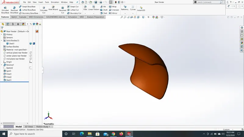
Then the Rear Fender is modeled. Initially the shape of the fender was drawn using line diagram and then it is revolved by the center axis using Revolve option to get the shape of the Fender. Then Split options are used to cut the Fender into the required shape. Then Shell option is used to create a shell around the Fender. Then some fillets are applied on the edges of the Fender. The appearance of painted car Siena material was used for the fender. The image of the Rear Fender is shown below.
- CHAIN
Next the modeled component is the Chain of the Chopper Model. It seems to be a more complex structure with more number of solid structures. At first the basic shape of the chain is drawn using line tool and circles. Then the inner and outer sprocket shapes of the chains are drawn by creating Blocks. Then these blocks are initially positioned in the line and extruded at first to get the basic shape. Then fillets are added to the structures. Then using Curve Driven Pattern option the extruded blocks are patterned along the shape of the chain with Tangent Propagation selected. Then similarly for the arc section the blocks are initially placed in the position and extruded with fillets applied and then curve drive pattern is made to complete the shape of the chain. Then for appearance polished copper is selected and the part diagram is saved. The part model of the chain is shown below.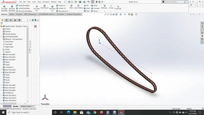 6. FRONT WHEEL
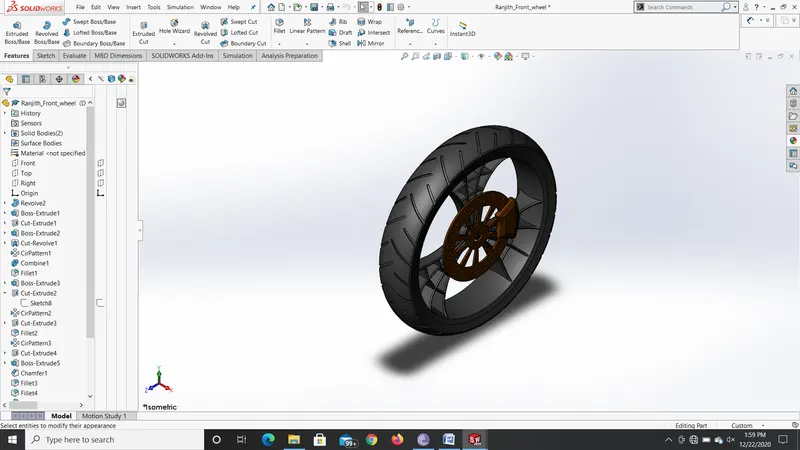
Now let us discuss about the modeling of the Front wheel of the Chopper. First the shape of the rim sketched using line tool and it is revolved to form the basic shape of the rim. Then the inner shape of the rim is drawn using line and spline tools to create a basic structure of the front wheel. Then it is mirrored using Mirror tool and Convert Entities option. Then it is cut extruded to form the basic shape of the spider web structure. Then the web structures are drawn using 3 point arcs and then it is extruded using boss extrude option to form the complete shape of the web Structured Rim. Then fillets are applied on the edges and then the entire structure is patterned using Circular Pattern option. Then the rotor of the wheel is drawn using the circle tool and then extruded to form the basic shape. Then for drawing the holes in the brake plate small circles are drawn and they are cut extruded and then patterned using Circular pattern option. Then the spokes on the plate are removed by drawing the shape using line tool and then Cut Extrude is used to remove the material. Then the caliper is drawn using line tool and extruded along the mid plane to form the complete structure. Then Fillets are applied on the edges of the wheel. Now the shape of the tire is drawn and revolved to obtain the shape of the tire. Then the spokes on the tire is drawn and extrude cut is used to cut the spokes and it is patterned circularly to obtain the complete shape of the tire. The appearance for the tire is gives as for the Rim and Rotor Chromium plate is used and for the caliper Siena is used and for the tire Matte Rubber material is used. The model of the front wheel is shown below.
- REAR WHEEL
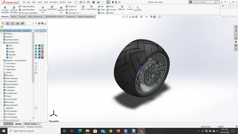
Now let us discuss about the modeling of the Rear wheel of the Chopper. First the shape of the rim sketched using line tool and it is revolved to form the basic shape of the rim. Then the inner shape of the rim is drawn using line and spline tools to create a basic structure of the front wheel. Then it is mirrored using Mirror tool and Convert Entities option. Then it is cut extruded to form the basic shape of the spider web structure. Then the web structures are drawn using 3 point arcs and then it is extruded using boss extrude option to form the complete shape of the web Structured Rim. Then fillets are applied on the edges and then the entire structure is patterned using Circular Pattern option. Then the rotor of the wheel is drawn using the circle tool and then extruded to form the basic shape. Then for drawing the holes in the brake plate small circles are drawn and they are cut extruded and then patterned using Circular pattern option. Then the spokes on the plate are removed by drawing the shape using line tool and then Cut Extrude is used to remove the material. Then the caliper is drawn using line tool and extruded along the mid plane to form the complete structure. Then Fillets are applied on the edges of the wheel. Now the shape of the tire is drawn and revolved to obtain the shape of the tire. Then the spokes on the tire is drawn and extrude cut is used to cut the spokes and it is patterned circularly to obtain the complete shape of the tire. Now the Sproket of the wheel is drawn by using circle option and then extruded using mid plane option. Now the teeth shape is drawn and then cut extruded and then patterned circularly along the circle to form the sprocket. The appearance for the Rear tire is gives as Chromium plate for Rim,Sproket and Rotor and for the caliper Siena is used and for the tire Matte Rubber material is used. The model of the Rear wheel is shown below.
- OIL TANK
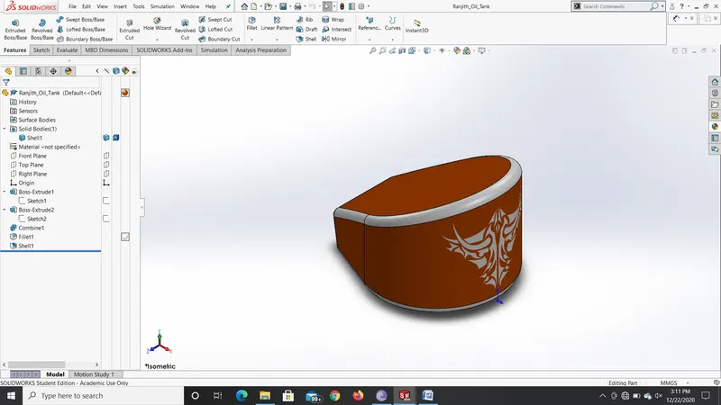
At first draw the basic shape of the oil tank and extrude it to form a rough shape of the oil tank. Then draw another shape on the other plane and extrude it about mid plane to form a shape. The obtained shape is irregular and hence in order to obtain the required geometry use split tool to remove the extra geometry. Now the required oil tank shape is obtained. Use combine option to combine both the shape and the resulting body is a single solid body with the desired shape. Now apply some fillets to the sides of the oil tank. And then apply shell option to create a cavity inside the oil tank. The appearance applied is the painted car Siena material for the oil tank. The part model of the oil tank is shown below.
- FRONT FORK
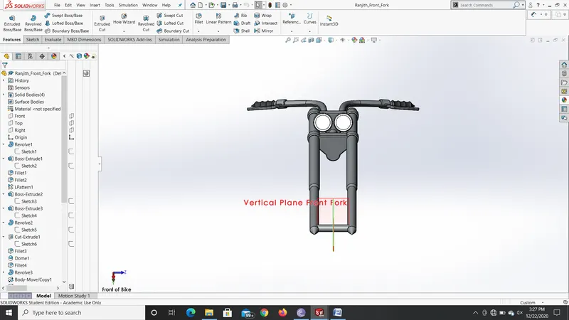
The front fork is a complex shaped geometry that is initially drawn on the front plane of the cad window. The shape of the fork is initially drawn using the line tool with reference lines in it. After the construction of these lines the shape is revolved about that construction line to form the basic structure of the fork. Now the shape of the front doom is drawn using lines and arcs and then extruded to form the upper surface of the fork. Then some fillets are applied on the side edges of the fork. Then a linear pattern is done to get the shape of the doom for 1 instances. Now the model is completed by sketching the required shapes and extruding it to complete the required shape of the fork. Then some fillet and dome is applied to the lights. Now the light is formed by revolving it with respect to the mid plane created about mid plane. Now to form the handle of the fork a curve is drawn using spline tool and it is onverted using the Sweep option. This forms the basic structure of the fork. Now a plane is created at exact mid plane to the model. And now it is mirrored about that mid plane to form the complete solid structure of the fork. Now the combine option is used to combine the mirrored part as a single solid structure. At last Chromium plate appearance is applied on the front fork. The part model is shown below.
- CHASSIS
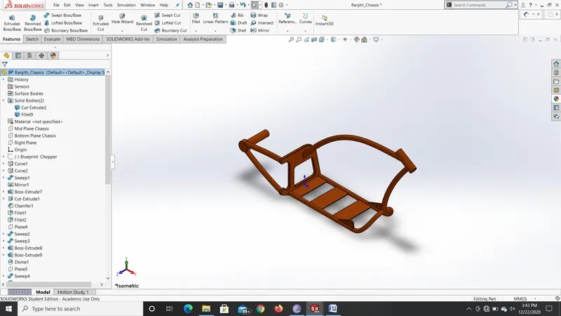
The chassis forms the basis of the chopper model because all the components are mounted on the chassis only. At first the curved surface of the chassis is done by drawing two curves and converting it to projected curves. Now at the end of the curve a circle is drawn and it is swept along the curve path to form the solid structure. And now it is mirrored about the mid plane to form the mirrored solid structure. Now the other side sketched with the help of line and arc tools and extruded to form a closure for the chassis structure. Now the centre is cut extruded to have the engine mount. Some fillets and chamfers are now applied to the chassis structure. Again with the help of arc and spline tools the curve is made and it is swept along the path to form a closed structure. Now the end face is sketched and extruded to mount the sprocket. Now some dome and combine feature are used to combine everything into a single solid structure. Now pedal mounts are sketched on the end and extruded and cut and fillets are applied on to the edges. Now mirror is used to mirror the component on the other side. Now combine option is used to form into a single component. At the end the painted car Siena material is used as appearance. The part model of the chassis is shown below.
- ENGINE
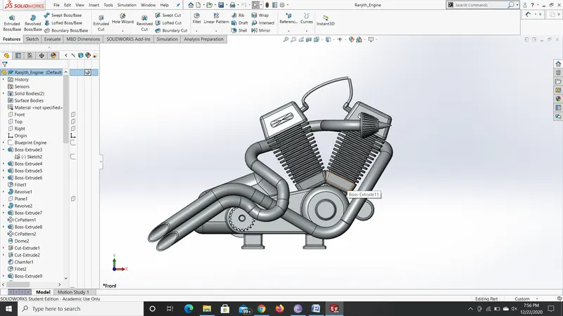
In the modeling of chopper Engine first the basic structure of the engine are modeled using line, circle and arc diagrams and then extruded to form a solid structure. The features like revolve applying fillets and chamfers are also done to obtain the basic structure of the engine model. Then in order to model the cylinder of the engine the structure is roughly drawn and feature like extrude boss, extrude cut, circular pattern and mirror are used to design the two cylinders of a V engine. Then fillets are applied on the edges of the cylinder linings. Then the exhaust pipe from both the cylinders are drawn using the 3 point arc and are aligned using projected curve option to get the actual profile of the exhaust pipe. Then these are extruded by using sweep option to obtain realistic solid structure of the engine. Then mounts are drawn on the sided to mount it in the chassis. Metal Chromium Plate was used as the appearance for the engine model. The part model is shown below.
- GAS TANK
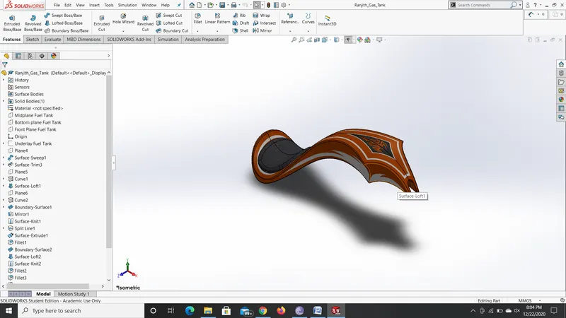
The designing of the Gas Tank is a completely different compared to other models because in this features like surface sweep, surface trim, surface loft, boundary surface, surface knit and fillets were used to design the component. Initially half of the component was designed and it was mirrored along the mid plane axis to have complete solid structure. Then fillet and shell option was used to show the realistic look of the gas tank along with some decals. The painted Siena material was used for the gas tank model. The gas tank model is shown below.
ASSEMBLY OF AMERICAN CHOPPER
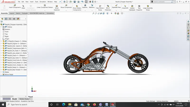
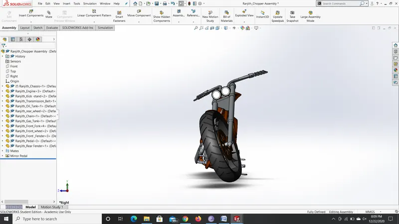
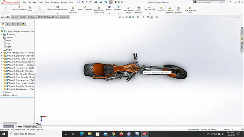
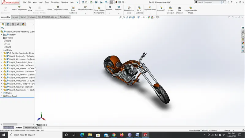
Once all the components are modeled and based on the design require dimensions all the components are assembled to have complete 3d solid structure of the American Chopper. Below are some of the images of the American Chopper Model.
FRONT VIEW
RIGHT SIDE VIEW
TOP VIEW
ISOMETRIC VIEW
CAMERA VIEW
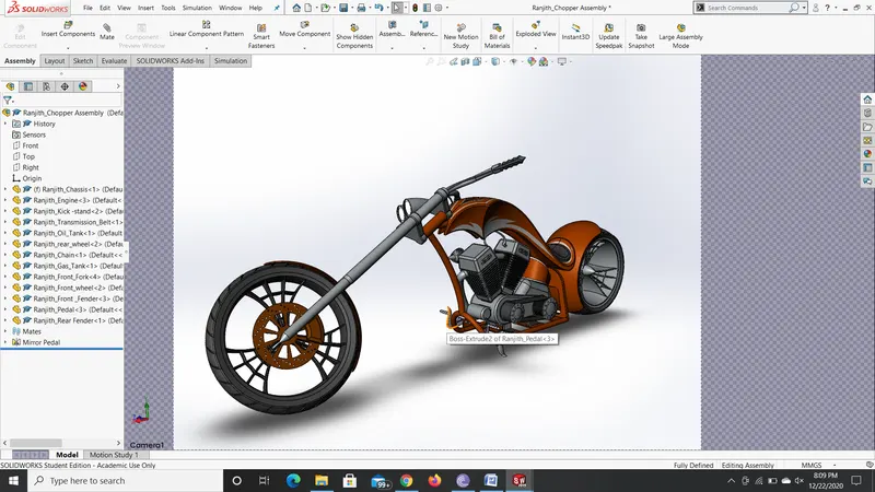
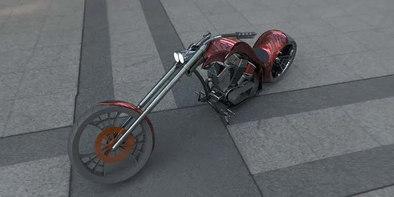
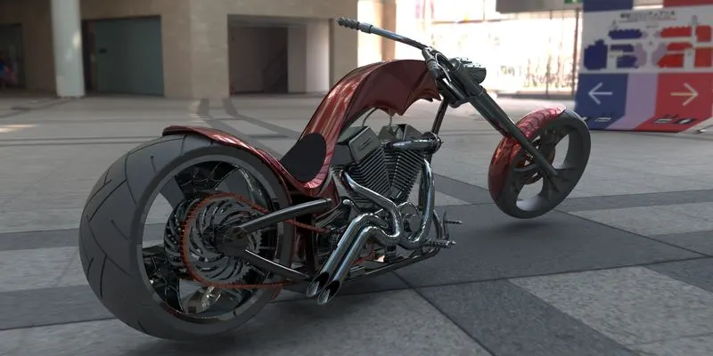
RENDERING IMAGES
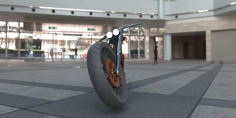
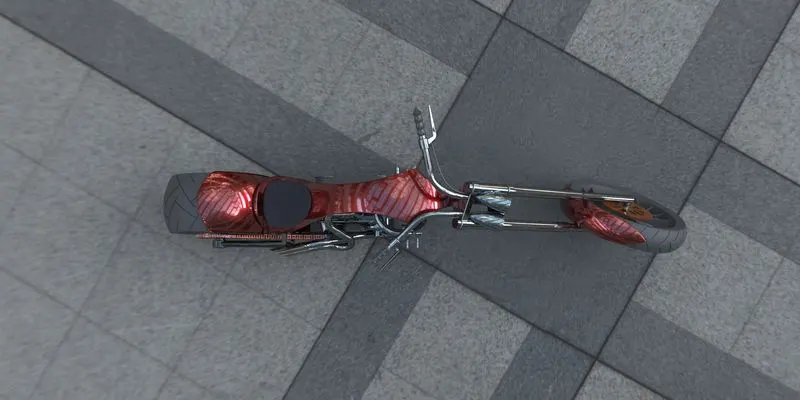
The rendering was done using Solid Works Visualize.
FRONT VIEW
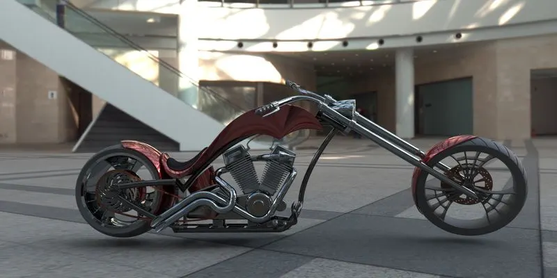
RIGHT SIDE VIEW
TOP VIEW
ISOMETRIC VIEW
CAMERA VIEW
CONCLUSION
Thus the complete model of the American Chopper was assembled and the images of which are also added within it. It took round 3 weeks to complete the entire model of the American Chopper.