Advanced Sheet Metal Design Using NX Cad Challenge_6_Bracket
BRACKET MODELLING USING SIEMENS NX
OBJECTIVE
The objective is to model a Bracket by using the application of Sheet Metal Design using SIEMENS NX 12 Software.
INTRODUCTION
The knowledge on the modeling of Sheet Metal plays a major role in the product design. Thus here is one of the application of sheet metal design is done using NX 12, where in different tools used for designing the sheet metal components are learnt, and here are some of tools used for designing the Bracket model is discussed below.
DESIGN METHODOLOGY
DESCRIPTION
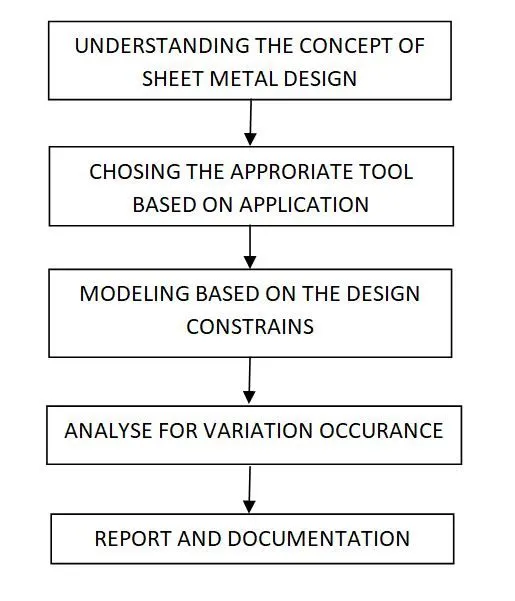
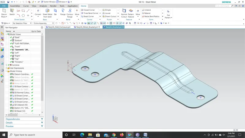
- At first the sketch is drawn in the plane and then Contour Flange option is used to create a Flange which forms the basic structure of the bracket.
- Then a Sketch is drawn to use the Normal Cutout feature to cut the part as needed.
- Then Break corner feature of different radius is applied on each sharp edge to have a smooth transition of the model.
- Then unbend feature is used to make a sketch on the top plane in order to create a Bead.
- Then Rebend option is used to gain its original required shape.
- Then some holes are made using simple holes option used for some mounting purposes.
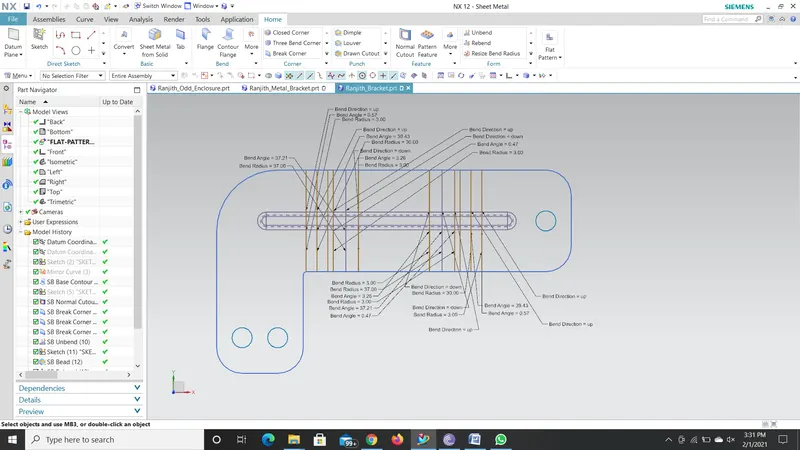
- Then Flat Pattern feature is used to create a Drawing sheet of the model.
SCREENSHOTS
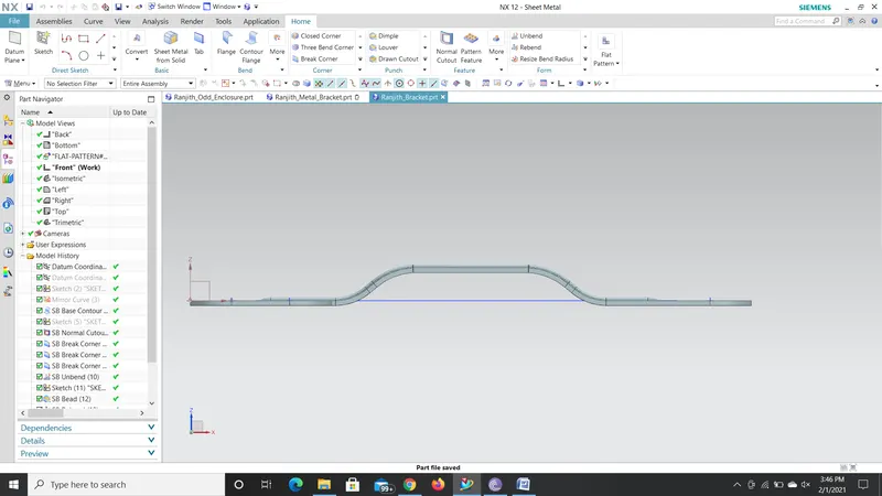
Front View
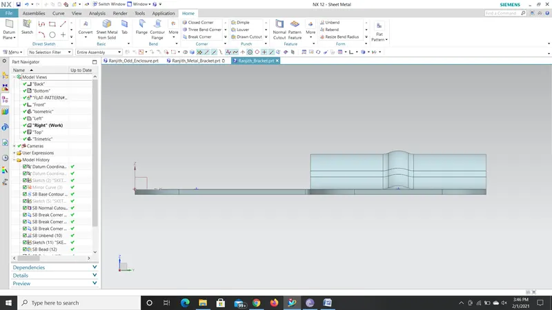
Right Side View
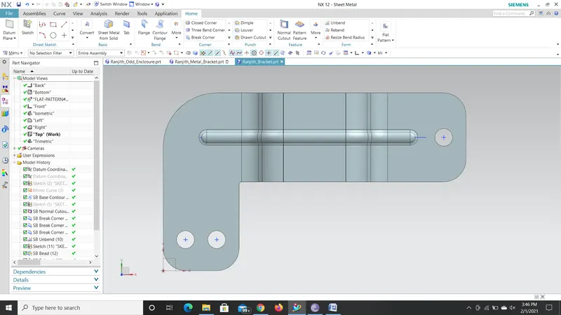
Top View
Isometric View
Drawing Sheet Image
Conclusion
Thus the modeling of Bracket is done using SIEMENS NX CAD 12.