Advanced Sheet Metal Design Using NX Cad Challenge_2_Box Assembly
BOX ASSEMBLY USING SIEMENS NX
OBJECTIVE
The objective is to model a Box Assembly by using the application of Sheet Metal Design using SIEMENS NX 12 Software.
INTRODUCTION
The knowledge on the modeling of Sheet Metal plays a major role in the product design. Thus here is one of the application of sheet metal design is done using NX 12, where in different tools used for designing the sheet metal components are learnt, and here are some of tools used for designing the Box Assembly model is discussed below.
DESIGN METHODOLOGY
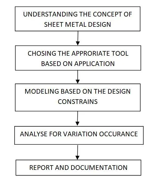
DESCRIPTION
- At first the tab feature was used to form a base shape of the sheet metal with a thickness of 2mm and the K factor of 0.33. This is the fixed value and the same was used till the end of the model.
- Then two Flanges on either side of the tab were used and then closed corner was used to close the corners of the Box Assembly. Then a series of Flanges and Hem Flange was used to have a basic structure of the model.
- Then mirror feature was used to convert the model onto the other side.
- Then Unite was used to join the two individual solid model into a single solid part.
- Then a sketch is made on the one of the box and Dimple feature is used on the side. Then the same feature is mirrored on the other side of the box.
- Then bend and unbend was used to see how the model reacts to the command.
- Then Beads are used on the bottom of the box and they are mirrored to form beads on the four corners of the box.
- Then a series of Hem Flanges are used and a sketch is drawn to close the one end of the box and then tab is used which makes our model closed.
- Then in order to create a open close mechanism for the box assembly features like bend, unbend, Flange, Hem Flange and normal cutouts were used to complete the Model of the Box Assembly.
SCREENSHOTS
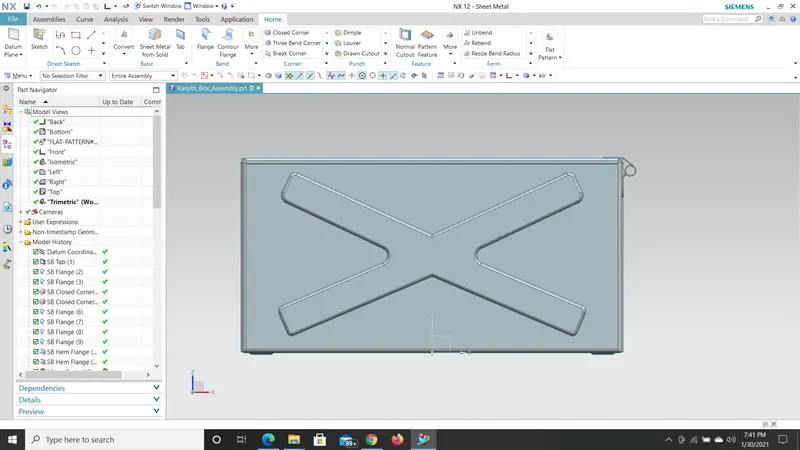
FRONT VIEW
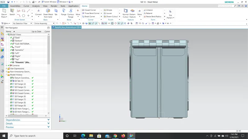
RIGHT SIDE VIEW
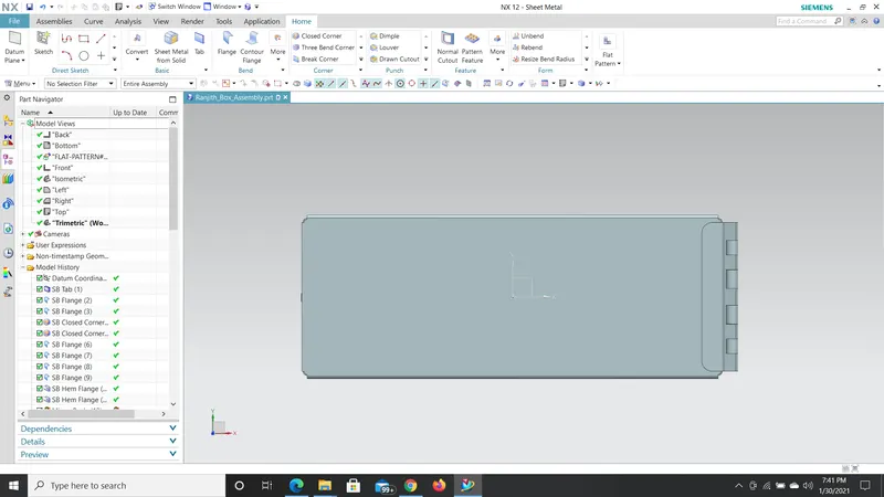
TOP VIEW
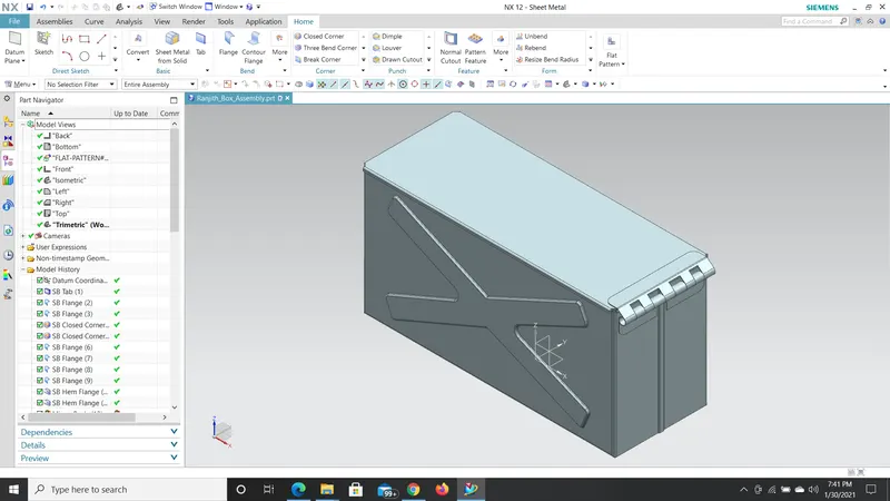
ISOMETRIC VIEW
DRAWING SHEET
CON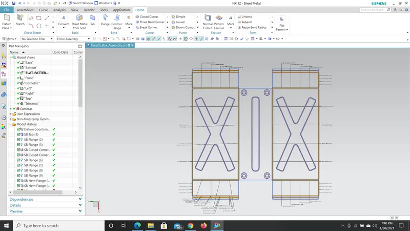 CLUSION
Thus the Box Assembly using SIEMENS NX has been completed.