Photo Realistic Rendering
Title: American Chopper Modelling in Solidworks
Objective: This is a detailed report on how the American chopper model was modeled as part wise and steps involved to integrate those parts as one assembly. The steps involved in rendering the American chopper final assembly is also enclosed in this report.
Introduction: So I initiated the modeling of the American Chopper by separately modeling the below listed crucial parts,
1. Front Fender
2. Rear Fender
3. Front Wheel
4. Rear Wheel
5. Drive Chain
6. Transmission Belt
7. Kick-stand
8. Pedal
9. Oil tank
10. Gas Tank
11. Engine, Motor & Exhaust
12. Front Fork
13. Chassis
The part functionalities and the modeling techniques used are elucidated vividly in the forthcoming explanations respectively,
Note: The Front, Top & Mid planes were modified according to the Individual part requirements.
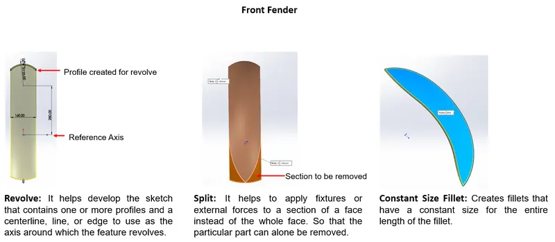
1. Front Fender: Fenders are primarily used to prevent the mud, rocks, liquids from being thrown into the air by the rotating tire. It also plays a vital part in aesthetics, in all the contemporary top-end models both the fenders have attractive and unique designs.
The following are the tools were utilized to create the Front Fender,
i) Revolve
ii) Split
iii) Fillet (Constant Size)
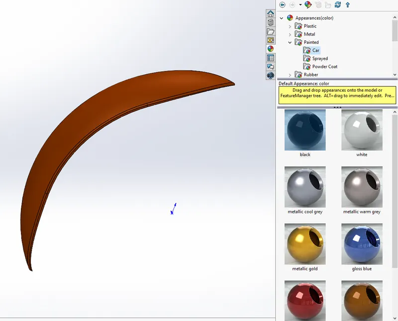
Finally, the appearance of the feature is given through the appearance tool in Solidworks.
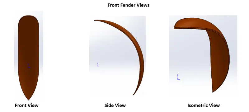
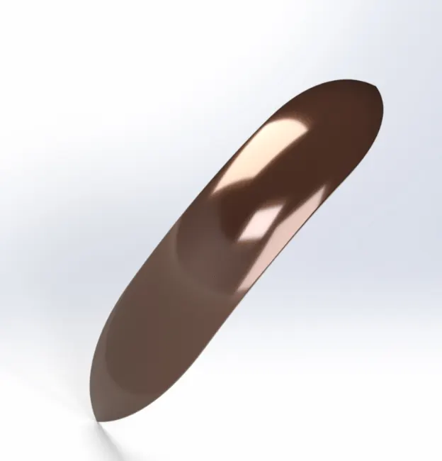
The below is the rendered image of the Front Fender using Solidworks Visualize,
By using the changing the parameters available within the tools of appearance and the environment, rendering has been done.
Rendered Image of the Front Fender:
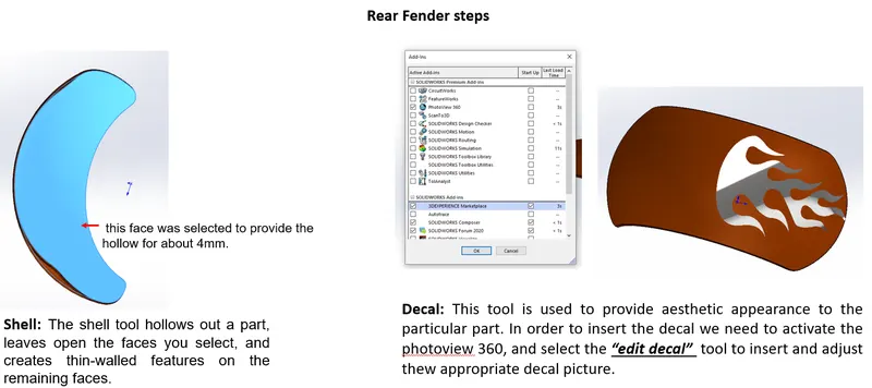
2. Rear Fender: The Rear fender also has a similar kind of function as stated above for Front fenders.
The following are the tools were utilized to create the Rear Fender,
i) Revolve
ii) Split
iii) Shell
iv) Decal
Note: The tools which I have used repetitively is not explained and unique tools used for the respective parts will be illustrated in the explanation.
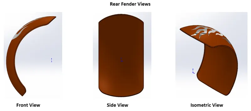
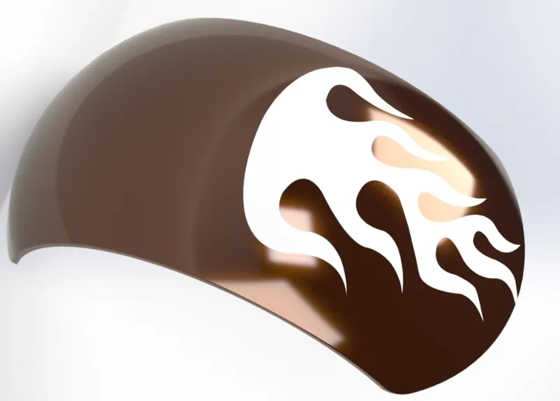
Rendered Image of the Rear Fender:
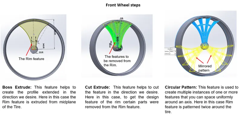
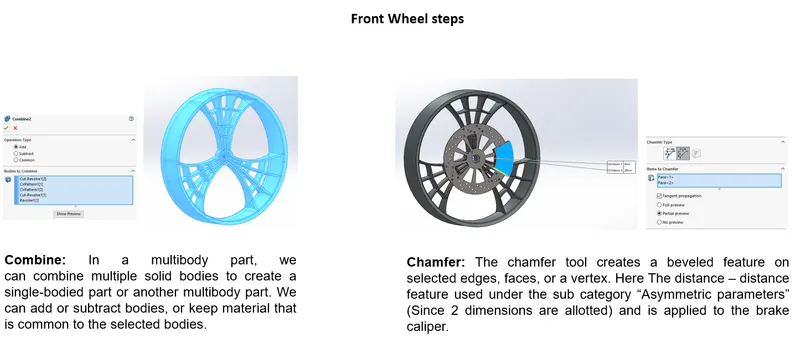
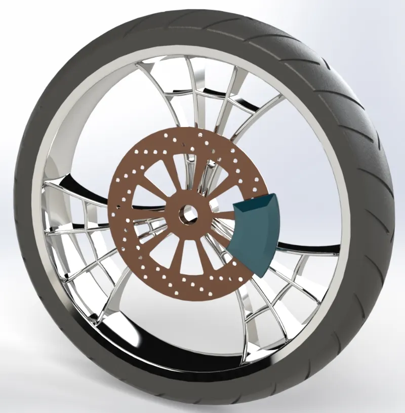
3. Front Wheel- The main function of the wheel is to maintain the traction of the vehicle on the road. the grip of the Tire mainly depends upon the thread pattern it has. In the Front-wheel Rotor and Caliper was also modeled, both of the parts will come under the "Disc brake System" of the two-wheeler. Disc brakes are the most efficient incumbent technology used to control the two-wheeler speed and stability on the road. The first mass-produced road-going motorcycle to sport a disc-brake was the 1969 Honda CB750 which was a very successful model for the company.
The following are the tools were utilized to create the Front Wheel,
i) Revolve
ii) Boss - Extrude
iii) Cut- Extrude
iv) Cut- Revolve
v) Circular Pattern
vi) Combine
vii) Fillet
viii) Chamfer
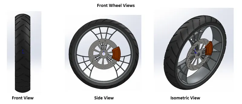
Rendered Image of the Front Wheel:
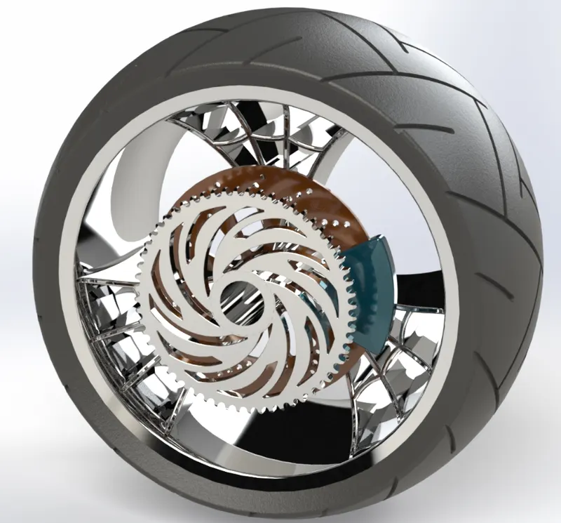
4. Rear Wheel: Most of the features of the Front wheel was just replicated in the rear wheel expect there was one more additional feature called the "Sprocket" which assists in the movement of the chain as the rotation of the motor.
The following are the tools were utilized to create the Rear Wheel,
i) Revolve
ii) Boss - Extrude
iii) Cut- Extrude
iv) Cut- Revolve
v) Circular Pattern
vi) Combine
vii) Fillet
viii) Chamfer
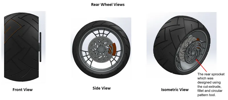
Rendered Image of the Rear Wheel:
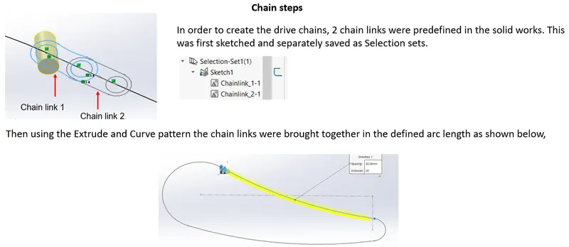
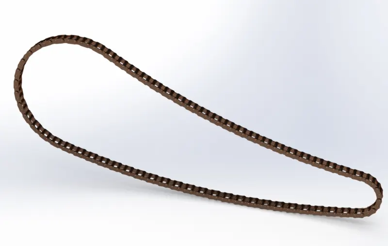
5. Drive Chain: The drive chain of a motorcycle is a very important element of the motorcycle drivetrain. Some bikes also use shafts and belts for the final drive but most motorcycles rely on-chain and sprocket setup for the job. The final drive is responsible for transferring the engine power to the rear wheel. While the mainstream street bikes use standard roller type chains, high-performance vehicles use O ring chains or X ring chains. The ring chains use rubber rings placed between the plates where they have got grease to keep the links running smooth. These chains are better described separately here.
The following are the tools were utilized to create the Drive Chain,
i) Boss - Extrude
ii) Fillet
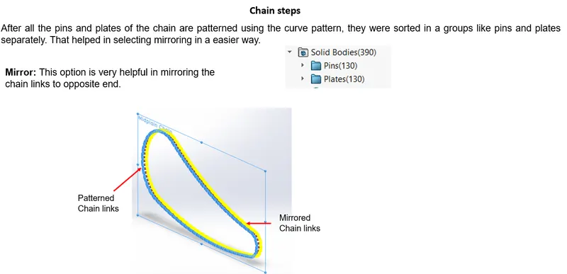
iii) Curve pattern
iv) Mirror
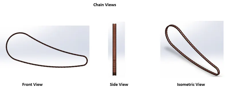
Rendered Image of the Drive Chain:
6. Transmission Belt: As in any transmission belt system, the flat belt allows a mechanical force to be transmitted from one pulley to another. The type of belt you should use depends on the type of application:
- torque to be transmitted
- rotational speed
- center distance
- reduction ratio
- temperature and lubrication conditions
The following are the tools were utilized to create the Transmission belt,
i) Boss - Extrude
ii) Fillet
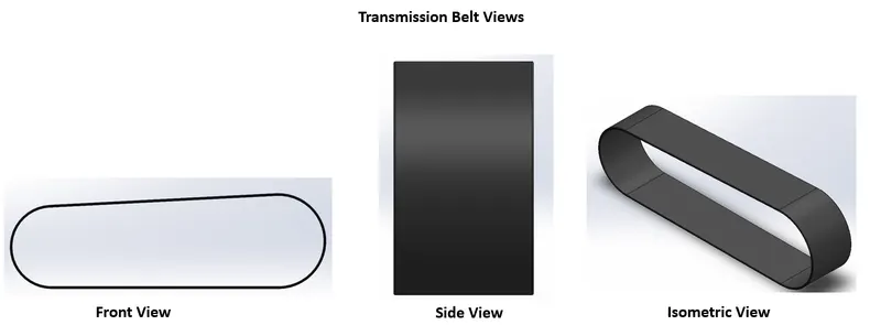
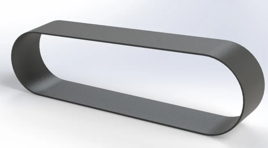
Rendered Image of the Transmission Belt:
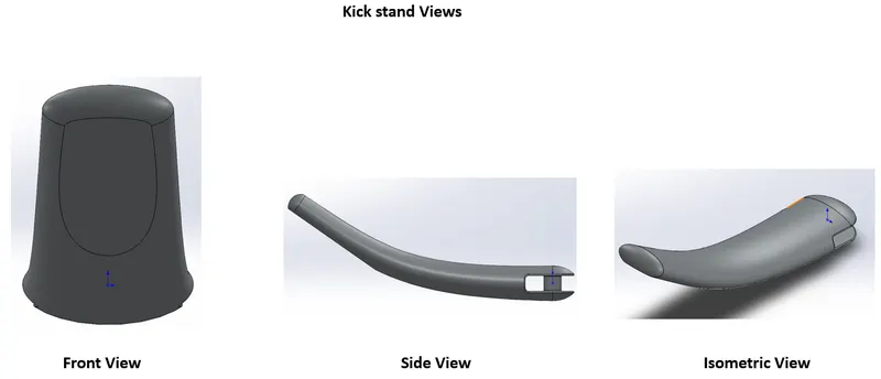
7. Kick Stand: This allows the bike to be kept upright without leaning against another object or the aid of a person. A kickstand is usually a piece of metal that flips down from the frame and makes contact with the ground.
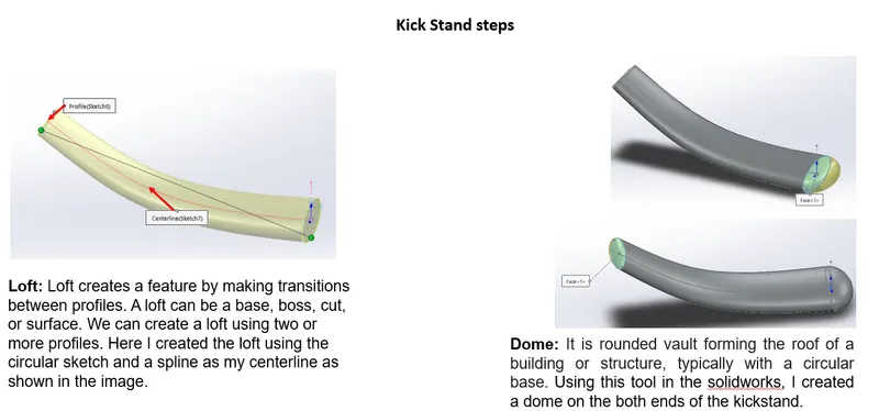
The following are the tools were utilized to create the Kickstand,
i) Loft
ii) Dome
iii) Cut-Extrude
iv) Split
v) Boss Extrude
vi) Fillet
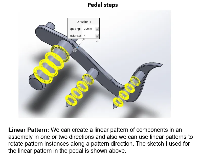
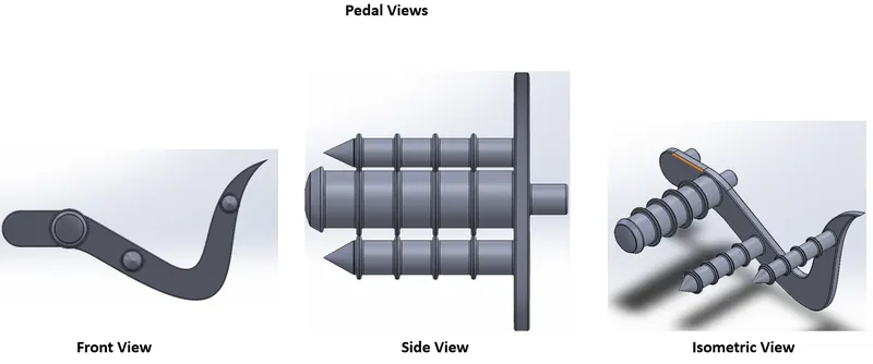
8. Pedal: This tool helps the driver to change the gear ratio by shifting the drive chain in the front sprocket (attached to the motor) according to the speed & torque requirements. It also allows the driver to rest his foot during the journey.
The following are the tools were utilized to create the Kickstand,
i) Boss Extrude
ii) Fillet
iii) Revolve
iv) Dome
v) Chamfer
vi) Linear Pattern
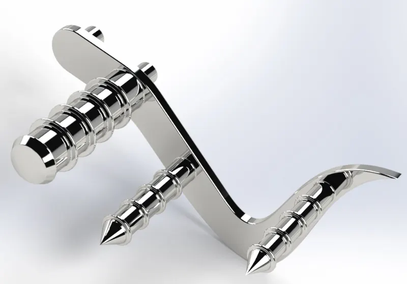
Rendered Image of the Pedal:
9. Oil Tank: This part in the American chopper stores the oil which is required for the lubrication of the engine and the motor in order to maintain the smooth operation and protects the parts from wear.
The following are the tools were utilized to create the Oiltank,
i) Boss Extrude
ii) Combine
iii) Fillet
iv) Shell
v) Decal
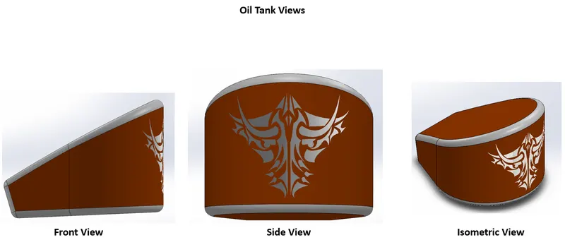
Rendered Image of the Oil Tank:
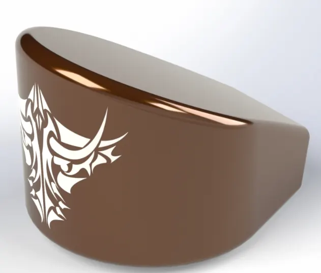
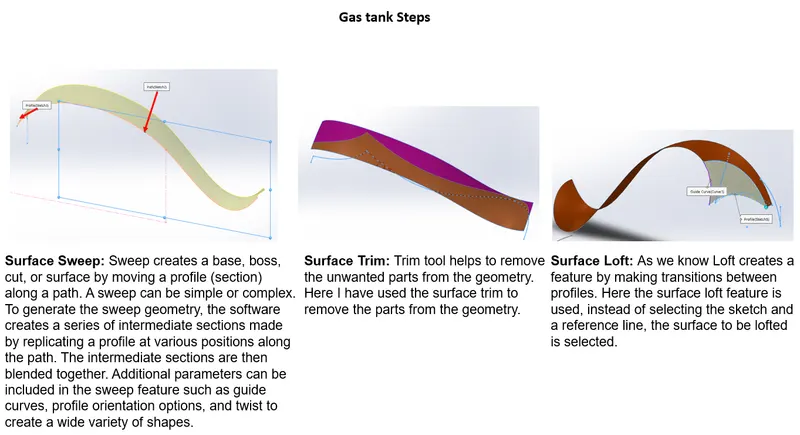
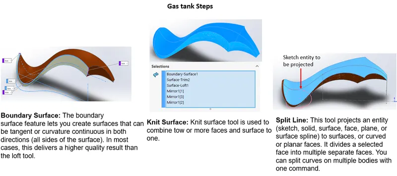
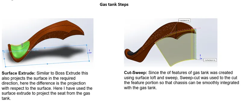
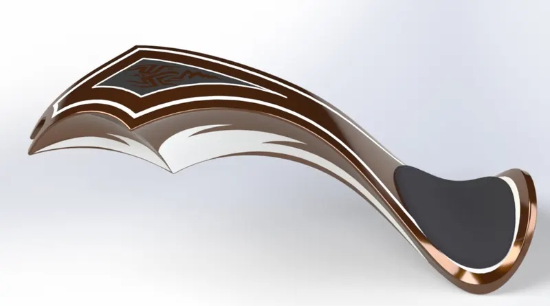
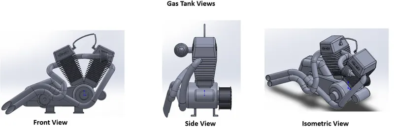
10. Gas Tank: This part helps to store the fuel (petrol/diesel) for the 2 wheeler.
The following are the tools were utilized to create the Oiltank,
i) Surface Sweep
ii) Surface Trim
iii) Surface Loft
iv) Mirror
v) Surface Knit
vi) Split Line
vii) Surface Extrude
viii) Boundary Surface
ix) Fillet
x) Cut-sweep
xi) Shell
xii) Decal
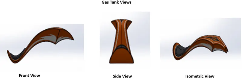
Rendered Image of the Gas Tank:
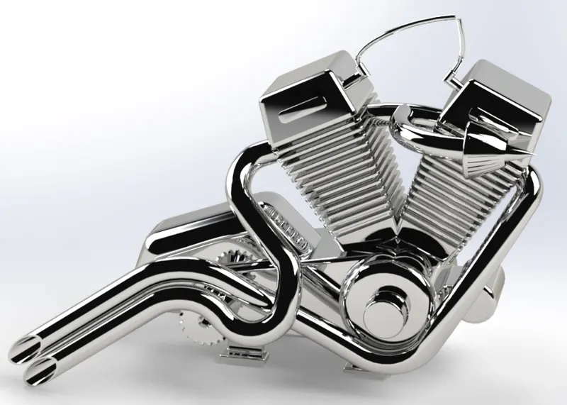
11. Engine, Motor & Exhaust: Engine and Motor are the sources of the energy that drives the vehicle from one place to another. The engine utilizes the fuel from the gas tank and drives the motor integrated with it. This motor in turn drives the transmission belt attached. The secondary motor attached to the transmission belt in turn moves the primary sprocket of the drive chain. The drive chain based on the gear ratio rotates the rear sprocket attached to the rear wheel.
The following are the tools were utilized to create the Engine, Motor & Exhaust,
i) Boss-Extrude
ii) Fillet
iii) Revolve
iv) Circular pattern
v) Dome
vi) Cut-Extrude
vii) Chamfer
viii) Fillet
ix) Linear pattern
x) Split
xi) Mirror
xii) Composite curve
xiii) Sweep
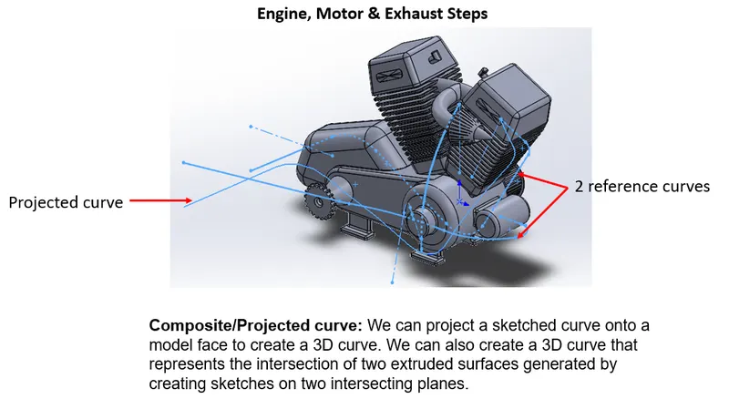
Rendered Image of the Engine:
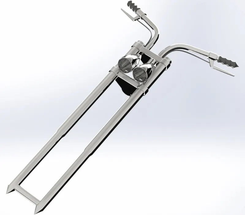
12. Front Fork: This holds the light and provides the longitudinal control of the vehicle to the driver as it directs the front wheel in the desired direction.
The following are the tools were utilized to create the Front Fork,
i) Boss-Extrude
ii) Fillet
iii) Linear Pattern
iv) Revolve
v) Cut-Extrude
vi) Dome
vii) Sweep
viii) Projected curve
ix) Mirror
x) Combine
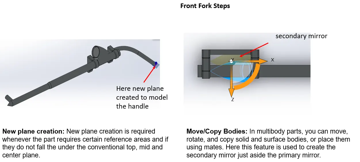
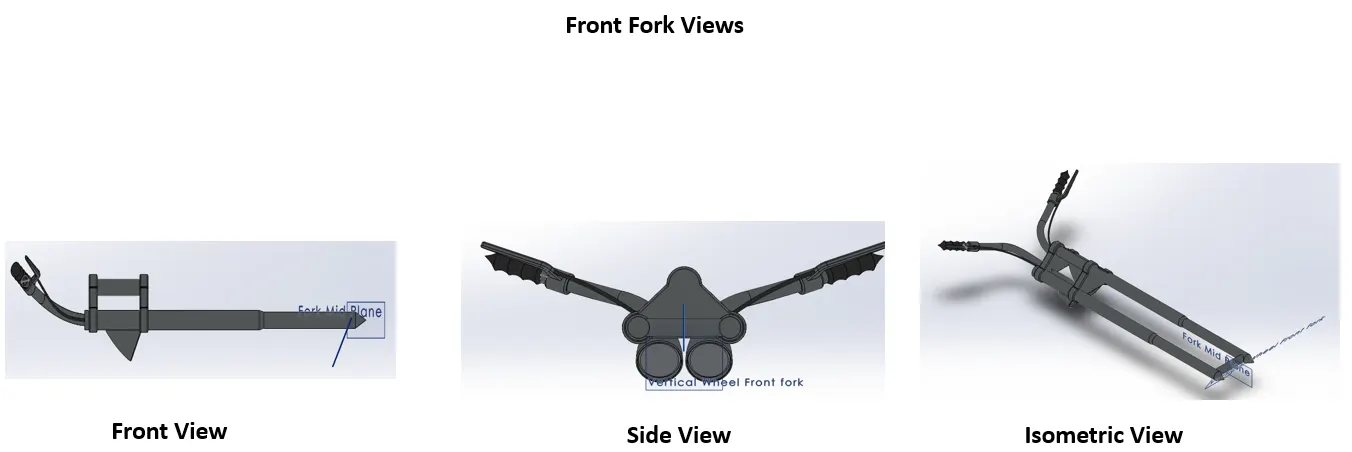
Rendered Image of the Front Fork:
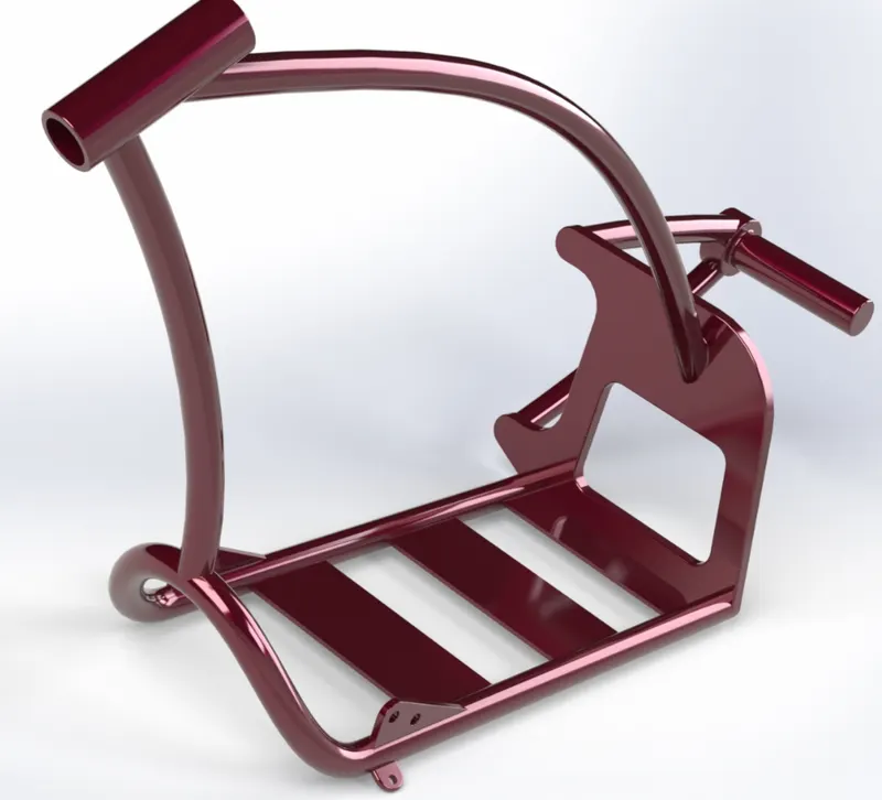
13. Chassis: It is the skeleton of the American Chopper, as it plays a crucial role in holding all the parts together.
The following are the tools were utilized to create the Chassis,
i) Composite/Projected Curve
ii) Sweep
iii) Boss-Extrude
iv) Fillet
v) Plane creation
vi) Dome
vii) Split
viii) Combine
ix) Cut-Extrude
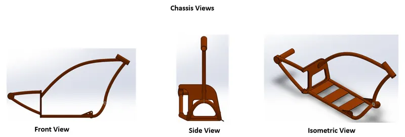
Rendered Image of the Chassis:
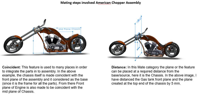
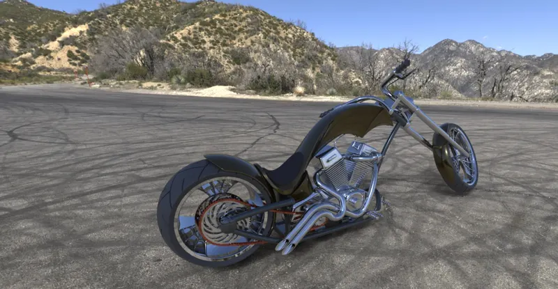
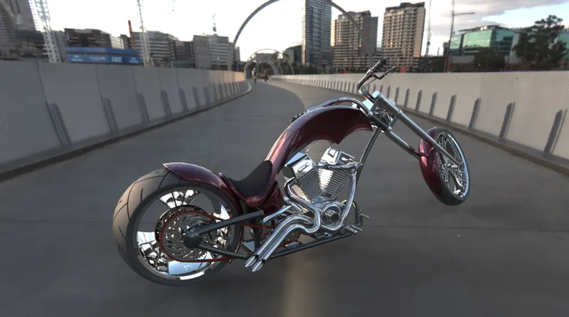
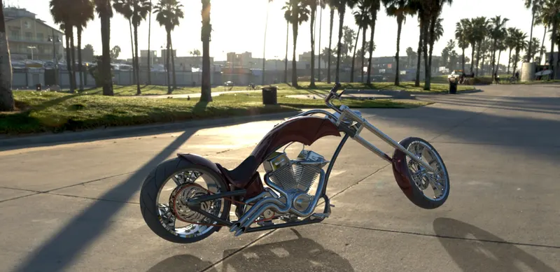
American Chopper Assembly: Here I incorporated all the 13 individual parts together into one assembly. To bring this one assembly I used the tool "Mate". Under this Mate tool, the following conditions were used
i) Coincident
ii) Distance
iii) Concentric
iv) Limit Angle
v) Width
vi) Parallel
vii) Tangent
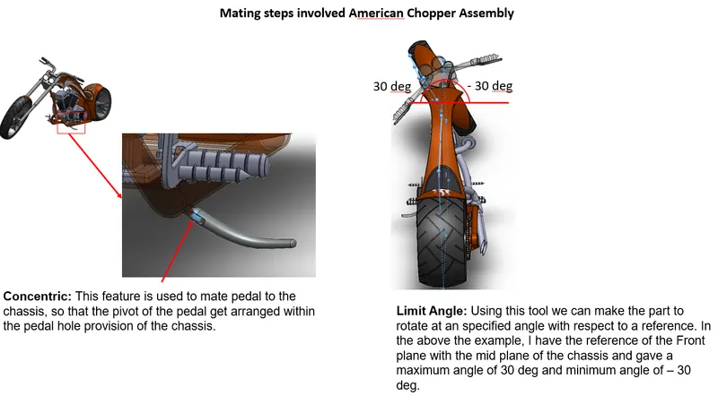
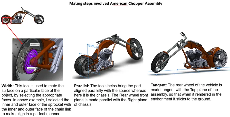
Along with this the pedal 2 was mirrored with respect to the midplane of the chassis since only one pedal was modeled initially.
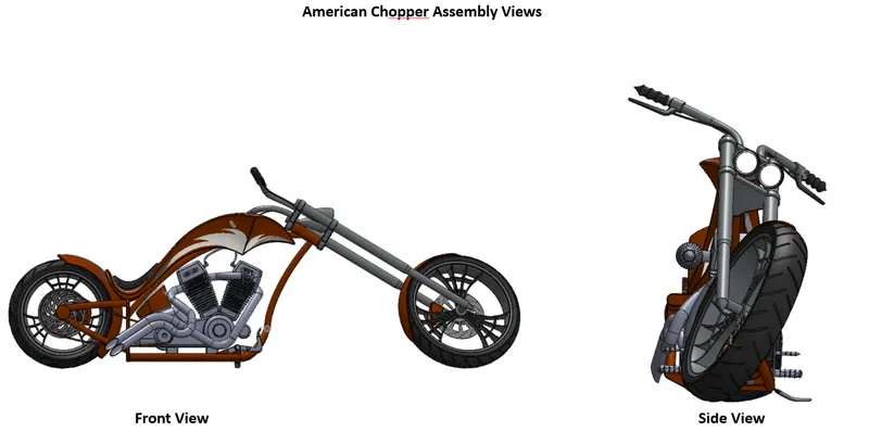
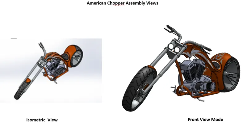
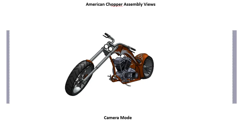
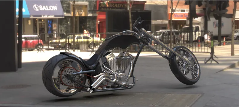
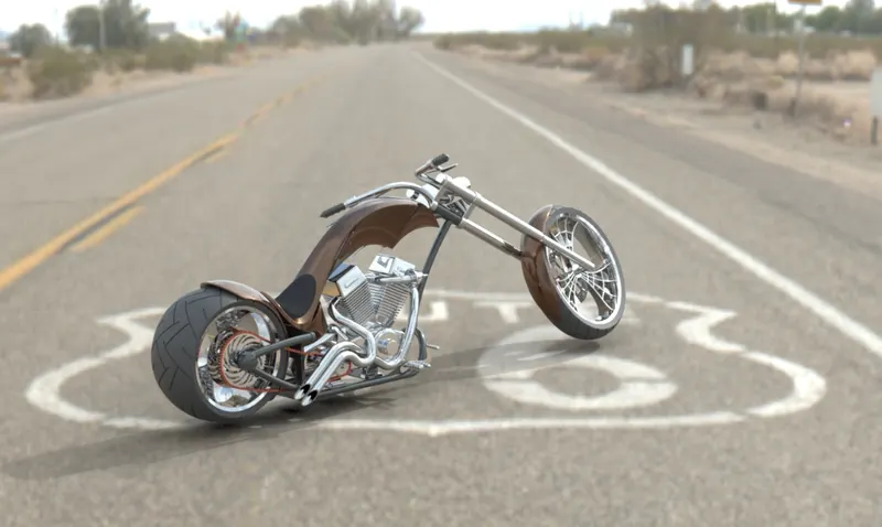
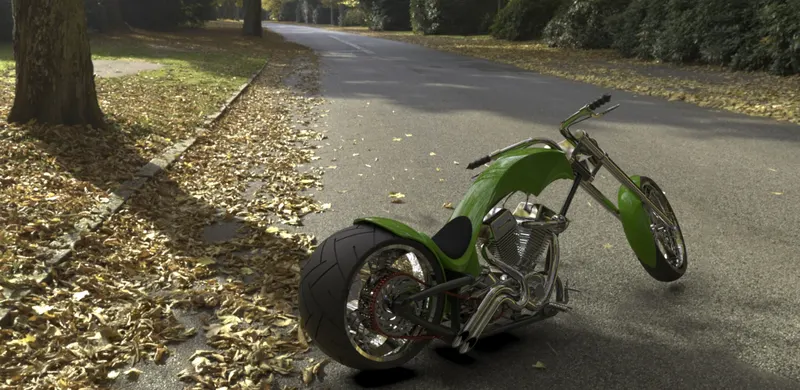
Rendered Images of the American Chopper
Conclusion:
i) The detailed procedure on how each part of the American chopper was modeled is vividly explained above. The unique tools used in each part alone was given explanation along with appropriate images.
ii) Then each part was rendered along with Assembly of the American chopper model using Solidworks Photo view.