Advanced Sheet Metal Design Using NX Cad Challenge_6_Bracket
Sheet metal Bracket using NX Cad
INTRODUCTION
This project is to learn and understand the features and tools of NX cad software for modelling a sheet metal bracket and to get a clear knowledge and understanding of the software.
OBJECTIVE
The main purpose and objective of this project is to understand and getting used to all the features and tools used in NX Cad software.
METHODOLOGY
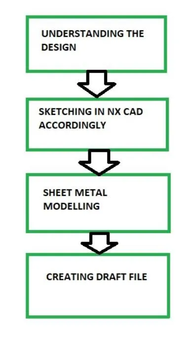
The first step is to understand the design of which we are going to model.
After that we will sketcch the model in NX cad.
Then using the appropriate feature and tools from the sheet metal we do the modelling.
After completing we draft the model.
DESCRIPTION
A. MODELLING
Tools/Features used-
-
Sketch
-
Contour flange
-
Normal cutout
-
Break corner
-
Unbend
-
Bead
-
Local radius analysis
-
Rebend
-
Simple hole
-
Flat pattern
First we create a plne on XZ plane. The we use contour flange which extrudes a sketch along a vector. Then from the top view we again sketch so that we can use the normal cut ut feature to cut a portion.
Then we use break corner to give a round around the corner. Then we use bead feature on the part which lifts a material along the contour of the sketch. Beads are also used to stiffen the sheet metal.
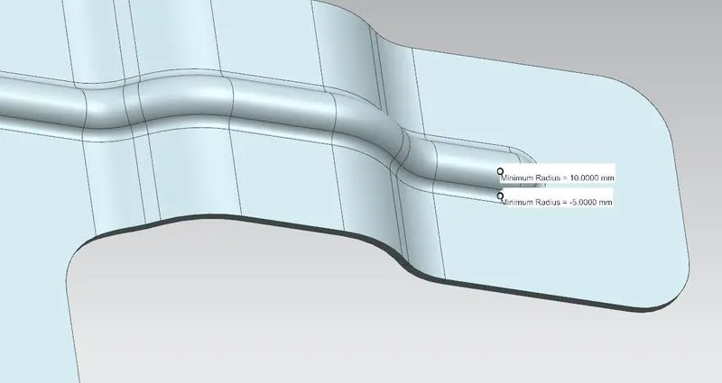
Local radius analysis is used to check the geometric properties os selected point on couve.
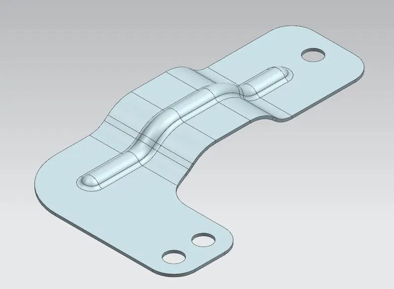
Then using the simple hole feature we create three holes on the bracket.
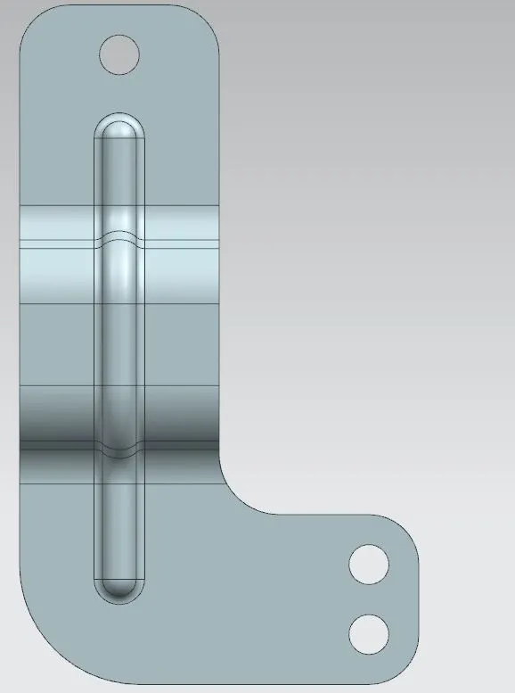
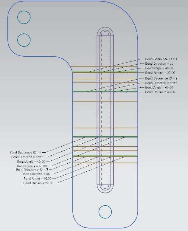
After using all these features and tool we have created the model. And then we create a flat pattern using the flat pattern feature. It helps in creating and visualizing the model in two dimension which makes it easier for manufacture.

B. DRAFTING
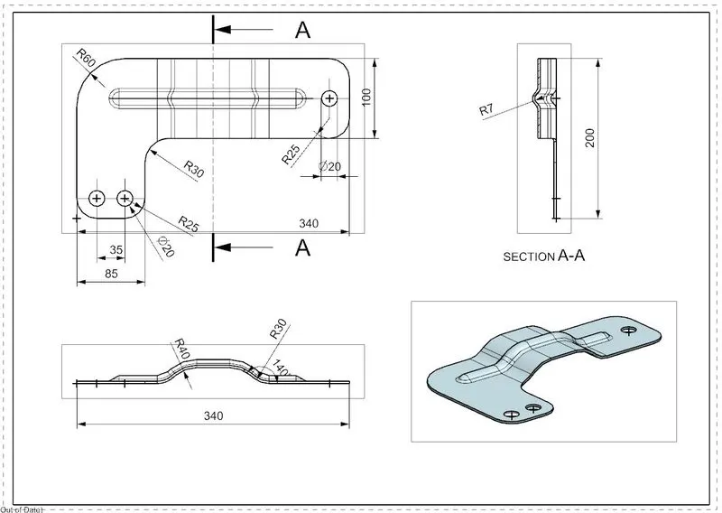
Drafting is nothing but creating two dimension drawing of the model for better understanding.
It also makes it easy for the manufacturer for understanding.
CONCLUSION
Thus we were able to model the part using all the above feature and we got to learn and understand above the features and tools of NX Cad.