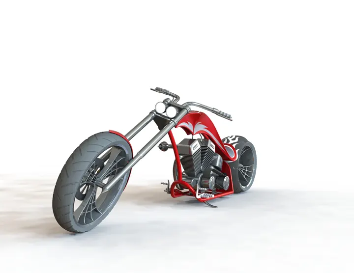
Designing an American Chopper with Photo realistic rendering
Design and Assembly of American Chopper Bike with photo realistic Rendering using SOLIDWORKS
OBJECTIVE
The objective of the project is to design and assemble the AMERICAN CHOPPER BIKE with photo realistic renderings using SOLIDWORKS 2020 in which the sketch should be fully defined and the mates in assembly should be fully constrained. Rendering should be done using PHOTOVIEW 360 and SOLIDWORKS Visualize Professional. Proper decals, cameras, lights and appearances should be added before rendering.
INTRODUCTION
SOLIDWORKS is a design automation software. SOLIDWORKS is published by Dassault Systemes. At the initial stage, the software is used for planning, visual ideation, modeling, feasibility assessment, prototyping, and project management. The software is then used for design and building of mechanical, electrical, and software elements.
SOLIDWORKS uses a 3D design approach. When designing a model using SOLIDWORKS, it can be visualized in three dimensions, the way the model exists once it is manufactured. One of the most powerful features in the SOLIDWORKS application is that any change made to a part is reflected in all associated drawings or assemblies.
Solidworks is used by students, designers, engineers, and other professionals to produce simple and complex parts, assemblies, and drawings. The Solidworks model is made up of Parts, Assemblies and Drawings. A part is a single 3D object made up of features. A part can become a component in an assembly, and it can be represented in 2D as a drawing. The extension for a Solidworks part file name is SLDPRT. Features are the shapes and operations that construct the part. The first, or base, feature is the foundation of the part and must always be created by adding material. An assembly is a document in which parts, features, and other assemblies (subassemblies) are joined (mated) together. The parts and sub-assemblies exist in documents separate from the assembly. For example, in an assembly of an engine, a piston can be mated to other parts, such as a connecting rod or cylinder. This new assembly can then be used as a sub-assembly in an assembly of an engine. The extension for a Solidworks assembly file name is SLDASM. A drawing is a 2D representation of a 3D part or assembly. The extension for a Solidworks drawing file name is SLDDRW.
American Chopper bikes are motorcycles built by Orange County Choppers (OCC) for a specific corporate or celebrity customer. Theme bikes are motorcycles in which the theme of the motorcycle takes priority over everything else, influencing the frame dimensions, paint scheme, and overall 'feel' of the motorcycle. The function of motorcycle usually takes a backseat to the presentation of the theme, and these motorcycles attract attention solely on the premise of the theme itself. Customers use the bikes for promotional purposes at tradeshows or auction them off as a charity fundraiser. The first chopper were built in America and tended to be based on HARLEY-DAVIDSON MOTORCYCLES. Rather than being primarily performance based modifications, choppers are more about achieving a certain look.
So, the purpose of the project is to create an aesthetic CHOPPER MODEL using SOLIDWORKS in which the sketch should be fully defined and the mates in assembly should be fully constrained.
DESIGN PROCESS
The design process involves the following steps:
- Identifying the model requirements.
- Conceptualize the model based on the identified needs.
- Developing the model based on the concepts.
- Analyzing the model.
- Prototyping the model.
- Constructing the model.
- Editing the model, if required.
DESIGN INTENT
The design intent for American Chopper is as follows,
- Modelling all the parts required to design the Chopper and applying the appropriate appearances.
- Assembling the model by applying the proper mates.
- Rendering the American Chopper to get a Photo-Realistic view using Photo view 360 and SOLIDWORKS Visualize Professional.
DESIGNING APPROACH
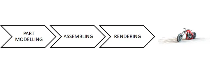
DESIGN METHODOLOGY
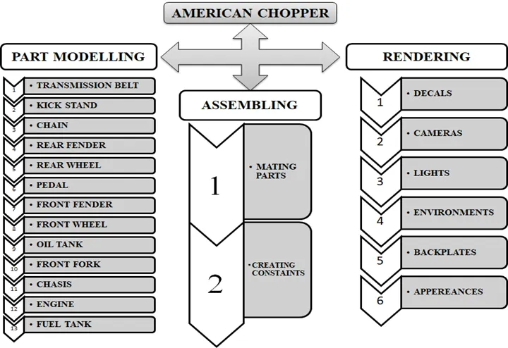
TERMINOLOGY
These terms appear throughout the SOLIDWORKS software and documentation.
Origin - Appears as two blue arrows and represents the (0,0,0) coordinate of the model. When a sketch is active, a sketch origin appears in red and represents the (0,0,0) coordinate of the sketch. Dimensions and relations can be added to a model origin, but not to a sketch origin.
Plane - Flat construction geometry. Planes can be used for adding a 2D sketch, section view of a model, or a neutral plane in a draft feature.
Axis - Straight line used to create model geometry, features, or patterns. Axis can be created in different ways, including intersecting two planes. The SOLIDWORKS application creates temporary axes implicitly for every conical or cylindrical face in a model.
Face - Boundaries that help define the shape of a model or a surface. A face is a selectable area (planar or non-planar) of a model or surface.
Edge - Location where two or more faces intersect and are joined together. Edges can be selected for sketching and dimensioning.
Vertex - Point at which two or more lines or edges intersect.
TYPES OF COMMANDS AND ITS EXPLANATIONS
Sketch - Create the sketches and decide how to dimension and where to apply relations.
Features - Select the appropriate features, such as extrudes and fillets, determine the best features to apply, and in what order to apply those features must be decided.
Surfaces - Surfaces are a type of geometry that can be used to create solid features.
Assembly - Select the components to mate and the types of mates to apply.
SKETCH COMMANDS
The sketch is the basis for most 3D models.
Creating a model usually begins with a sketch. From the sketch, we can create features. We can combine one or more features to make a part. Then, we can combine and mate the appropriate parts to create an assembly. From the parts or assemblies, we can then create drawings.
A sketch is a 2D profile or cross section. To create a 2D sketch, we use a plane or a planar face. In addition to 2D sketches, we can also create 3D sketches that include a Z axis, as well as the X and Y axes.
There are various ways of creating a sketch. All sketches include the following elements:
- ORIGIN
- PLANES
- DIMENSIONS
- DRIVING DIMENSIONS
- DRIVEN DIMENSIONS
- SKETCH DEFINITIONS
- SKETCH RELATIONS
- SKETCH COMPLEXITY
Smart Dimension - Creates a dimension for a selected sketch entity.
Line - Line is one of the first sketching tools in Solidworks Sketch Command Manager which can be drawn horizontally, vertically or at any angle. It plays very important role to complete the 2D drawing of the product or part and very easy to utilize its features.
Circle - The circle is another important sketching tool which enables to create the circular drawing on the graphics area. There are two circle tools are available and they are “Center circle” and “Perimeter circle”.
Rectangle - Sketches rectangles or square with a center point at a selected angle. Parallelogram sketches a standard parallelogram.
Spline - A two or three dimensional curve defined by a set of control points. Points within a spline can be added or deleted.
Ellipse - Sketches a complete ellipse.
Tangent Arc - An incomplete circle defined by its tangency to the sketch entity.
Sketch Fillet - A tangent arc in between two sketch entities can be created.
Point - Inserts a point or vertex into a sketch entity. This cannot be deleted if it is part of sketch endpoint or center point.
Offset Entities - Copy a sketch entity to a specified distance from the original entity. Must have a sketch entity already drawn and selected to use this tool.
Sketch Picture - Insert an image file into the background of a sketch. This allows the user to 2D sketches based off of the image. Use the sketch picture property manager to alter the inserted image.
Mirror Entities - Create a reflected copy of a desired entity about a centerline or axis.
Move Entities - Dimensions are moved or copied to the new location with the entities. Relations are moved or copied only if we select Keep relations.
Linear Sketch Pattern - Pattern a sketch entity either horizontally, vertically, or angled. Under the property manager the user can specify the distance between the original sketch entity and the patterned copy, the number of instances, and an angle the pattern will appear. Sketch entities can be skipped by selecting the drop down arrow in instances to skip, selecting the text box, and then left clicking the patterned entities to skip.
The circular pattern tool can be found under the drop down arrow. It performs similarly to the linear sketch pattern except that it requires the user to specify a point to revolve about and a radius.
Convert Entities - Convert Entities enables you to copy model edges into your active sketch. These sketch elements are automatically fully defined and constrained with an On Edge relation. Convert Entities is like Offset Entities except that the offset distance is always zero.
Intersection Curve – Tool Intersection Curve opens a sketch and creates a sketched curve at the following kinds of intersections,
- A plane and a surface or a model face.
- Two surfaces.
- A surface and a model face.
- A plane and the entire part.
- A surface and the entire part.
Trim Entities - Sketch entities can be trimmed shorter using the Trim Entities tool. The Trim Entities tool can remove sketch entities by several different methods. The most common method is to trim to the closest entity. This method removes the entity from the point where it is selected to the nearest intersection with another sketch entity.
Extend Entities - You can add to the length of a sketch entity (line, centerline, or arc). Use Extend Entities to extend a sketch entity to meet another sketch entity.
Sketch Contours - Sketch Contours allow you to select portions of a sketch that are generated by the intersection of geometry and create features. This way you can use a partial sketch to create features. Another advantage of this method is that the sketch can be reused, creating separate features from different portions of the sketch.
FEATURE COMMANDS
Some sketch-based features are shapes such as bosses, cuts, and holes. Other sketch-based features such as lofts and sweeps use a profile along a path.
Another type of feature is called an applied feature, which does not require a sketch.
Applied features include fillets, chamfers, or shells. They are called “applied” because they are applied to existing geometry using dimensions and other characteristics to create the feature.
Typically, we create parts by including sketch-based features such as bosses and holes. Then we add applied features.
It is possible to create a part without sketch-based features.
Extruded Boss/Base - One of the oldest commands in the SOLIDWORKS software is the boss/base extrude command. An Extruded Boss/Base feature will allow us to take a 2D sketch and add thickness to it in the third dimension.
Extruded Cut - It’s a tool to remove material by projecting a sketched section normal to the sketching plane.
Circular Patters - Circular Patterns create copies, or instances, in a circular pattern controlled by a center of rotation, an angle and the number of copies. The instances are dependent on the originals. Changes in the originals are passed on to the instanced features.
Linear Pattern - It is a tool to copy the original tab a specified number of times. The linear pattern creates multiple instances of a selected feature along a linear path.
Curve Driven Pattern - The Curve Driven Pattern tool allows us to create patterns along a planar or 3D curve. To define the pattern, we can use any sketch segment, or the edge of a face (solid or surface), that lies along the plane. We can base our pattern on an open curve, or on a closed curve, such as a circle.
Sketch Driven Pattern - The sketch driven pattern creates copies of existing features and places them wherever we've added a point in a sketch. It's that simple. All it takes is a sketch created specifically to place instances of a feature.
Shell - The shell tool hollows out a part, leaves open the faces we select, and creates a thin-walled features on the remaining faces. If we do not select any face on the model, we can shell a solid part, creating a closed, hollow model. We can also shell a model using multiple thicknesses.
Edit Feature - Edit Feature provides a simple method to change the information used to create a feature. To edit any feature, right-click the feature either in the Feature Manager design tree or the graphics area, and select Edit Feature.
Revolved Features - Material can be added or removed from a model by using the Revolve command. Revolves add or remove material by revolving one or more profiles around a centerline. We can create revolved boss/bases, revolved cuts, or revolved surfaces. The revolve feature can be a solid, a thin feature, or a surface.Revolved featured are created by rotating a sketch around a centerline. The centerline becomes the axis of revolution.
Degrees of Freedom - There are six degrees of freedom for any component that is added to the assembly before it is mated or fixed: translation along the X, Y, and Z axes and rotation around those same axes. How a component is able to move in the assembly is determined by its degrees of freedom. The Fix and Insert Mate options are used to remove degrees of freedom.
Fillet - Filleting refers to both fillets and rounds. The distinction is made by the geometric conditions, not the command itself. Fillets are created on selected edges. Those edges can be selected in several ways. Both fillets (adding volume), and rounds (removing volume), are created with this command. The orientation of the edge or face determines which is used.
The Full Round Fillet option creates a fillet that is tangent to three adjacent sets of faces. Each face set can contain more than one face. However, within each face set, the faces must be tangent continuously. A Full Round Fillet does not need a radius value. The radius is determined by the shape of the faces you select.
The Chamfer tool creates beveled faces. A chamfer, like a fillet, is an applied feature, and does not require you to make a sketch to create the feature.
Section View - Section View cuts the view using one or more section planes. The planes can be dragged dynamically. Reference planes or planar faces can be used. To check our work and see how the parts fit together, we can use the section view.
Mirror - Features can be mirrored about a plane or planar face. The mirrored features maintain a relationship with the original features such that any changes to the original features are also made on the mirrored features.
A mirror sketch entity is a copy of a selected sketch entity that is mirrored about a centerline. If the original feature or sketch is modified, the mirrored copy is updated to reflect the change.
Split - Lines are used to divide model faces into two. Split lines are created like any other sketched feature. They can be one or more connected sketch entities. They must be oriented so that they will pass through model faces when projected normal to the sketch plane.
Combine - In a multi body part, we can combine multiple bodies to create a single body. We can only combine bodies contained within one multi body part file. We cannot combine two separate parts.
Dome - It can add one or more domes to the selected planar or non-planar faces. The software calculates the distance using the radius of the arc as a basis for the dome.
Sweeps - Sweeps take a sketch, called a Profile and move it along a Path. It must be a closed, non-self-intersecting boundary. However, the sketch can contain multiple contours - either nested or disjoint.
Sweeps can also be used to remove material as a Swept Cut. Guide curves may meet at a common point, which is the apex of the swept surface.
Lofts - Lofts create a solid by connecting a series of loft profiles. These profiles can be different shapes. Lofted Boss/Base adds material between two or more profiles to create a solid feature. Lofted cut was used to remove material from two or more profiles. The first, last or the first and last profiles can be the points.
Pierce Relationships - The Pierce relationship is used in sweeps. It can be thought of as a 3D Coincident relationship. In our spring, the circle will follow the helix. Think of the helix as a thin piece of wire and the profile sketch as being drawn on a piece of paper. If we stick the wire through the paper at the center of the circle, this would be a pierce relationship. When we perform the sweep, the paper will slide along the wire, held at the pierce point.
Block - A block is a user-defined annotation for drawings only. A block can contain text, sketch entities (except points), and area hatch, and it can be saved in a file for later use.
Reference Geometry - Reference geometry defines the shape or form of a surface or a solid. Reference geometry includes items such as planes, axes, coordinate systems, and points. We can use reference geometry in the creation of several kinds of features. For example: Planes are used in lofts and sweeps.
Project Curve - Select Bi-directional to create a projection that extends on both sides of the sketch. The curve can be used as a path for a sweep.
Composite Curve - We can create composite curves by combining curves, sketch geometry, and model edges into a single curve. Composite curve can be used as a guide curve when creating a loft or a sweep.
Split Line - The Split Line tool is used to project an entity (sketch, solid, surface, face, plane, or surface spline) onto other surfaces or curved/planar faces. We are also able to split faces on multiple bodies with one command.
Assembly Exploded Views - Exploded views are created to make it easier to see how an assembly is put together and to see the parts that are normally hidden from view.
DESCRIPTION
1.TRANSMISSION BELT
A belt is a loop of flexible material used to link two or more rotating shafts mechanically, most often parallel. Belts may be used as a source of motion, to transmit power efficiently or to track relative movement. Belts are the cheapest utility for power transmission between shafts that may not be axially aligned. Power transmission is achieved by purposely designed belts and pulleys. The variable power transmission needs that can be met by a belt-drive transmission system are numerous, and this has led to many variations on the theme. Belt drives run smoothly and with little noise, and provide shock absorption for motors, loads, and bearings when the force and power needed changes. A drawback to belt drives is that they transmit less power than gears or chain drives. However, improvements in belt engineering allow use of belts in systems that only formerly allowed chain drives or gears.
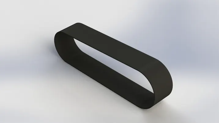
COMMANDS USED TO MODEL
In Sketch
- Line
- Arc
In Features
- Offset
- Extrude
- Fillet
- Appearances
MODELLING PROCEDURE
- Front plane was used to create the sketch for transmission belt.
- Using line command a horizontal line is drawn from the origin to the right and an arc, tangent to the line drawn was sketched continuously.
- From the end of the first arc another line was drawn horizontally towards left.
- Another arc was drawn to connect both the horizontal lines.
- The connecting points of the arcs are made to be tangent to the horizontal lines.
- Starting point was made to be coincident with the origin and the required dimensions were applied using Smart dimensions tool.
- Now the sketch was fully defined and then offset the sketch inwards in such a way that it creates a thickness for the transmission belt.
- Then the sketch was extruded from sketch plane using blind option and the required fillets were added along the edges of the belt on both sides.
- Now the part was saved by adding the matte rubber appearance.
2.KICK STAND
A kickstand is a device on a motorcycle that allows the bike to be kept upright without leaning against another object or the aid of a person. A kickstand is usually a piece of metal that flips down from the frame and makes contact with the ground. A side stand style kickstand is used in this model. It is a single leg that simply flips out to one side, usually the left side, and the bike then leans against it. Side stands can be mounted to the chain stays right behind the bottom bracket or to a chain and seat stay near the rear hub. Side stands mounted right behind the bottom bracket can be bolted on, either clamping the chain stays or to the bracket between them, or welded into place as an integral part of the frame.
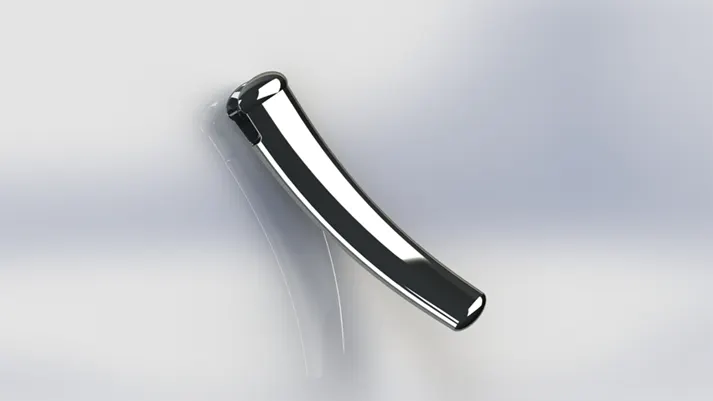
COMMANDS USED TO MODEL
In Sketch
- Ellipse
- Spline
In Features
- Pierce
- Split
- Lofted Boss/Base
- Extruded cut
- Extruded Boss/Base
MODELLING PROCEDURE
- An ellipse was sketched on the front plane and made it center point coincident with the origin.
- Then a spline was created from the origin on the Mid Plane and applied the required dimensions.
- A new plane was generated normal to the spline using plane tool from reference geometry.
- Using the reference plane another ellipse was sketched and its center point must be made pierced with the end point of the spline.
- Then by using the Lofted Boss/Base tool a loft was created between the two ellipse and then it was made to align with the spline using centerline parameters.
- Then two domes were created on either side of the lofted model by using the dome feature for the required dimensions.
- Now on bottom right side a rectangular extruded cut was made on the mid plane using Extruded Cut with Through All-Both option for making a clamping socket.
- Then a circular holder was extruded in between the clamping socket by sketching a circle on the top plane.
- Then a small portion of the part from the lower side of the kickstand has been split away using split tool for having a perfect ground clearance.
- Finally the part was saved by adding the fillets for the required edges and applying the chrome appearance.
3.CHAIN
A bicycle chain is a roller chain that transfers power from the pedals to the drive-wheel of a bicycle, thus propelling it. Most bicycle chains are made from plain carbon or alloy steel, but some are nickel-plated to prevent rust, or simply for aesthetics. Bicycle chains are made of multiple pairs of steel outer plates and inner plates held together by rivets. A roller separates each pair of inner plates. The rivet (pin) is pressed tightly through both outer plates. The rivet then pivots freely on the inner plates and roller.
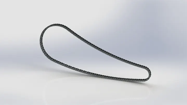
COMMANDS USED TO MODEL
In Sketch
- Circle
- 3 Point-Arc
In Features
- Slot
- Block
- Fillet
- Curve Driven Pattern
- Mirror
MODELLING PROCEDURE
- For modeling the chain first a pathway for the chain was created using arc command.
- Then the outside chain link and the inside chain link has been sketched on the mid plane using the circle, line and arc commands and saved it as blocks.
- Then both the links were extruded to the mid plane by using the insert block command and Extruded Boss/Base.
- Now the pins were created and the fillets were applied as required.
- Then by using the Curve Driven Pattern copy the chain links and pins along with the pathway we created for the chain.
- Now the chain links are mirrored parallel to the current links of the chain using Mirror command.
- Now the part file was saved by adding proper fillets as required and applying the chrome appearance.
4.REAR FENDER
Fenders make a tremendous difference when you are riding roads that are wet from drizzle, recent rain, or snowmelt. In a hard rain, you may become wet with clean rain from above, but fenders will protect your body and bicycle from the mud and sand kicked up from dirty puddles and rivulets.
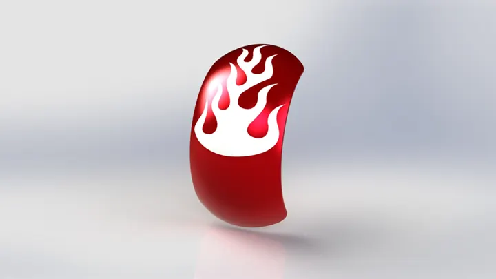
COMMANDS USED TO MODEL
In Sketch
- 3-Point Arc
- Spline
- Offset Entities
- Extend Entities
- Trim Entities
In Features
- Revolved Boss/Base
- Fillet
- Shell
MODELLING PROCEDURE
- A 3 Point Arc was sketched on the front plane and applied the required dimensions using Smart Dimensions tool.
- Then offset the arc towards inward using Offset Entities tool and join the two arcs by sketching a line on both sides.
- Then a construction line was drawn horizontally from origin and the required sketch relations were added for creating a revolve using Revolved Boss/Base.
- Now for giving a smooth edge for our fender a curve was drawn on the top plane and split the portion which was not required.
- Then a shell was created on the inside face of the fender and the fillets were added throughout the edges.
- Now the part was saved by applying an appropriate appearance.
5.REAR WHEEL
One is located at the rear of the bike, which is rotated through the transfer of energy via a belt, or (more commonly) a chain that is then linked to the drive system. The rear wheel is fixed in place in the frame so although the wheel freely rotates it does not pivot or change angle. The rear wheel often featuring more spokes to improve strength and stiffness. A wheel is a circular block of a hard and durable material at whose center has been bored a hole through which is placed in an axle bearings about which the wheel rotates when torque is applied to the wheel about its axis. The wheel and axle assembly can be considered one of the six simple machines. When placed vertically under a load-bearing platform or case, the wheel turning on the horizontal axle makes it possible to transport heavy loads.
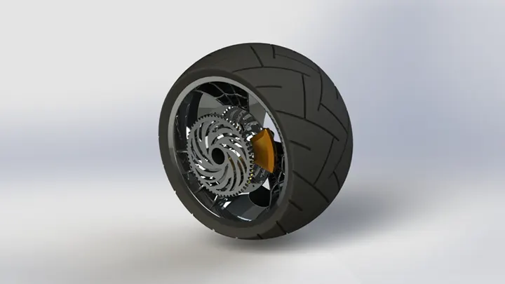
COMMANDS USED TO MODEL
In Sketch
- Line
- 3-Point Arc
- Sketch Fillet
- Spline
- Extend Entities
- Trim Entities
- Corner Rectangle
- 3-Point Center Rectangle
- Convert Entities
- Intersection Curve
- Linear Sketch Pattern
In Features
- Extruded Boss/Base
- Revolved Boss/Base
- Extruded Cut
- Revolved Cut
- Circular Pattern
- Fillet
- Chamfer
MODELLING PROCEDURE
- The Rear Wheel consist of five Solid Bodies,
- The Rim
- The Rotor
- The Sprocket
- The Caliper
- The Tire
- First the Rim was designed by creating the required sketch on the front plane and applying proper dimensions using Smart Dimensions.
- The created sketch was used to create a revolve using Revolved Boss Base and Circular Pattern options.
- The Rim has been designed to have a spider web shaped rim wheel.
- Proper fillets were added and applied the chrome appearance.
- Now the Rotor has been designed by sketching two circles on the right plane.
- The first circle was used to create a hub for the wheel using Extruded Cut option.
- By using the Linear Sketch Pattern sketch four circles in sideways on the rotor and use Extruded Cut.
- By using Circular Pattern the holes on the Rotor for the required no of instances has been created.
- Now for designing the Caliper the required sketch was drawn and extruded using the Arc, Trim Entities and Extruded Boss/Base command.
- Then the Chamfer has been applied for the required dimensions and gave the Sienna appearance.
- Now the Sketch for the Sprocket is drawn on the right plane and extruded. For creating the gear teeth around the sprocket Circular Pattern was used and proper fillets were added for the edges to get smooth edge on the teeth.
- Finally the Tire has been designed by drawing the required sketch on the front plane and revolved around the rim.
- To create a grip on the wheels the tire should have some cut extrudes over the tire which was created using Circular Pattern, Extruded Cut and Fillets. Now complete the design by applying Matte Rubber appearance.
- Now the Part was saved.
6.PEDAL
The gear shift lever is located on the lower left side of the motorcycle. By sliding your left foot under the gear shift lever and lifting it upward, you shift to a higher gear. Each click equals one gear. You can always find first gear by tapping the gear shift lever down until it won't go any further. Most manual transmission two-wheelers use a sequential gearbox with five or six gears to shift into using a foot lever.
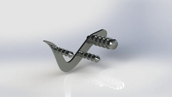
COMMANDS USED TO MODEL
In Sketch
- Lines
- Circles
- Spline
In Features
- Fillet
- Chamfer
- Revolved Boss/Base
- Dome
- Linear Pattern
MODELLING PROCEDURE
- First the required sketch to model the pedal has been drawn and dimensioned it using Lines, Arcs and Splines.
- Then the foot rest part was sketched and extruded using Extruded Boss/Base and applied the proper fillets.
- Now using construction line and normal line the required sketch was drawn on the top plane and then the sketch was revolved with respect to the construction line.
- Now the dome has been created over the face of the foot rest.
- Then the circular extrude was created using Offset, Fillet, Chamfer and Linear Pattern options.
- Finally the part was saved by adding Chrome appearance.
7.FRONT FENDER
Fenders are also called as mudguards. These mudguards are fixed over the front tire of the bike. It protects bike rider from water and mud caused to thrown up by the bike. A front fender will help protect your feet and ankles from spray if you're riding in the rain or even through a puddle.
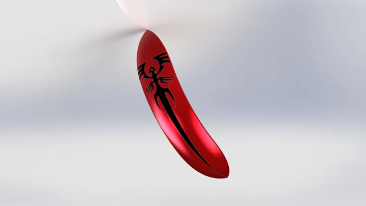
COMMANDS USED TO MODEL
In Sketch
- 3-Point Arc
- Spline
In Features
- Offset
- Extend Entities
- Trim Entities
- Revolved Boss/Base
- Fillet
MODELLING PROCEDURE
- For modeling the Front Fender the required sketch was drawn on the front plane and revolved using Revolved Boss/Base.
- Then by using Split option the unwanted portion has been removed and then the fillets were added around the edges to get a smooth edge for the fender.
- A Shell was created on the inside face of the fender.
- Now the part was saved by adding an appropriate appearance.
8.FRONT WHEEL
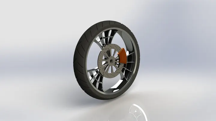
In this model we use spider webbed spoke wheels. Spokes are the connecting rods between the bicycle hub and the rim. Their main purpose is to transfer the loads between the hub and the rim, which are caused by the weight of the rider and the bike. A spoke wheel is typically (though not always) made of steel, which is heavier. The outer rim of this wheel is connected with the inner hub with wired spokes. The construction of an alloy wheel can be highly automated, though spoke wheels require some amount of human inputs as they’re made of multiple components.
COMMANDS USED TO MODEL
In Sketch
- Line
- 3- Point Arc
- Sketch Fillet
- Spline
- Extend Entities
- Trim Entities
- Center Point Rectangle
In Features
- Revolved Boss/Base
- Extruded Cut
- Offset
- Revolved Cut
- Circular Pattern
- Fillet
- Chamfer
MODELLING PROCEDURE
- The Front Wheel consist of four Solid Bodies,
- The Rim
- The Rotor
- The Caliper
- The Tire
- The modeling procedure for the Front Wheel is as same as the Rear Wheel except the part sketch.
- So the required sketch was drawn on the required plane and applied the required dimensions.
- Then the same procedure for modeling the Rear wheel is used to create the rim, the rotor, the caliper and the tire of the Front Wheel.
- Finally the part was saved by adding an appropriate appearance.
9.OIL TANK
American Chopper has oil tanks because the engine has a dry sump system, meaning the oil is constantly pumped through the engine with an oil pump. So the engine either has a tank, or the oil pan is at lower engine height but behind the engine.
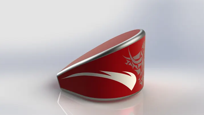
COMMANDS USED TO MODEL
In Sketch
- Line
- 3-Point Arc
In Features
- Shell
- Fillet
- Combine
- Extruded Boss/Base
MODELLING PROCEDURE
- First a horizontal construction line from the origin was drawn on the top plane then a midpoint line was drawn vertically connecting the construction line on the left side.
- Then two lines from the either ends of the vertical line were drawn with required sketch relations. Then the lines were connected by drawing a 3-Point Arc which is tangent to that line
- Now the fully defined sketch was extruded and another sketch was drawn on the front plane and extruded.
- Now the Combine option is used to combine both the extruded parts with the common operation type and a shell were created using Shell feature.
- Finally the part was saved by adding the proper fillets along the edges and applying an appropriate appearance.
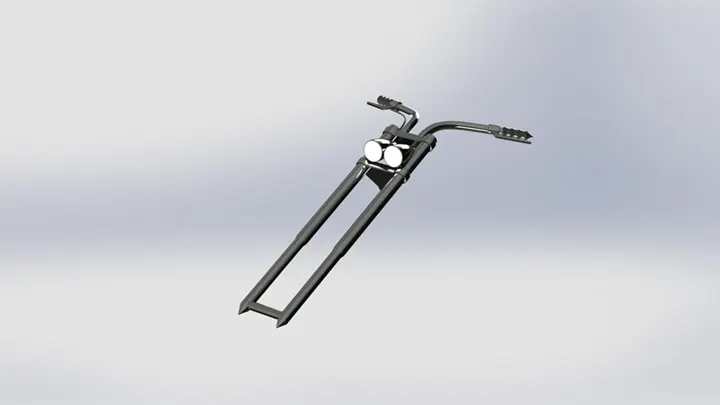
10.FRONT FORK
A motorcycle fork connects a motorcycle's front wheel and axle to its frame, typically via a yoke, also known as a triple clamp, which consists of an upper yoke joined to a lower yoke via a steering stem, a shaft that runs through the steering head, creating the steering axis. Most forks incorporate the front suspension and front brake, and allow the front wheel to rotate about the steering axis so that the bike may be steered. Most handlebars attach to the top clamp in various ways, while clip-on handlebars clamp to the fork tubes, either just above or just below the upper triple clamp. Most motorcycles today use telescopic forks for the front suspension. The forks can be most easily understood as simply large hydraulic shock absorbers with internal coil springs. They allow the front wheel to react to imperfections in the road while isolating the rest of the motorcycle from that motion.
A motorcycle handlebar is a tubular component of a motorcycle's steering mechanism. Handlebars provide a mounting place for controls such as brake, throttle, clutch, horn, light switches and rear view mirrors and they help to support part of the rider's weight.
COMMANDS USED TO MODEL
In Sketch
- Line
- Circle
- Spline
In Features
- Revolved Boss/Base
- Extruded Cut
- Reference Plane
- Reference Axis
- Fillet
- Mirror
- Combine
- Dome
- Linear Pattern
- Swept Boss/Base
- Project Curve
- Body Move
MODELLING PROCEDURE
- To design the Front Fork half side of the fork has been created and the remaining half was mirrored using the first half.
- Hence the first half of the fork has been sketched on the front plane and revolved using Revolved Boss/Base.
- The crown part of the fork was designed using the Extruded Boss/Base and the base crown was created using Linear Pattern and the crowns were connected by using extrude thin feature.
- The Through Axle was used to hold the Front Wheel and it was also created using Extruded Boss/Base.
- For creating the head lights the required sketch was drawn on the front plane and revolved using Revolved Boss/Base.
- For creating the glass face on the head light Dome and Extruded Cut feature was used and applied the required fillets.
- The Cut Revolve and Body Move options were used to get the head light looks realistic and for positioning perfectly.
- Project Curve and Swept Boss/Base tools were used to create the handle bars and brake wires.
- For creating the handles a new plane was created using reference geometry plane command on the handle bar and revolved using Revolved Boss/Base.
- For creating the brake Extruded Boss/Base were used and proper fillets were added.
- Then the other half of the handle bars were created using Mirror command and then the forks and handle bars were combined separately with the other half using Combine command.
- Now the part was saved by applying Matte Rubber appearance to the handles and brake wires and Chrome appearance for forks and handlebars.
11.CHASIS
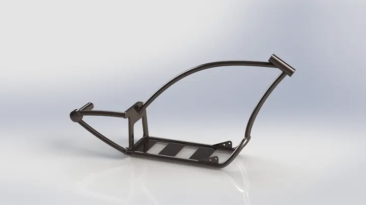
A chassis is the load-bearing framework of an artificial object, which structurally supports the object in its construction and function. Chassis is the main support structure of the vehicle which is also known as 'Frame'. It bears all the stresses on the vehicle in both static and dynamic conditions. In a vehicle, it is analogous to the skeleton in living organisms. A motorcycle's chassis or frame forms its skeleton. All the components of a motorcycle, like the suspension, wheels, fuel tank, seats, handlebars etc, are attached to this base structure which lends a motorcycle its strength and ability to handle well. Back bone frame, Single cradle frame, Double cradle frame, Perimeter frame, Trellis frame and Monocoque frame are the types of motorcycles frame by construction.
COMMANDS USED TO MODEL
In Sketch
- Sketch Picture
- Spline
- Arc
In Features
- Mirror
- Extruded Boss/Base
- Revolved Boss/Base
- Swept Boss/Base
- Project curve
- Reference Geometry
- Extruded Cut
- Chamfer
- Fillet
- Dome
- Split
- Combine
MODELLING PROCEDURE
- First the blueprint was added using insert sketch pictures option on the mid plane. The blueprint was used to structure the sketch of the Frame.
- The Bottom Rails for placing the engine were created by drawing a projected curve and the curve was swept using Swept Boss/Base and the other half was mirrored.
- The Back Frame was created using Extrude Boss/Base and Revolved Cut. Finally the required chamfer and fillets were added.
- The Bottom Tail Tube was created using Swept Boss/Base and Extruded Boss/Base. Dome option was used to create a dome on the front face of the Hub.
- For creating the Steer tube Extruded Boss/Base and Extruded Cut was used.
- For creating the Foot Pedal Mounts Extruded Boss/Base, Extrude Cut, Mirror and Fillet were used.
- Split and Combine options were used to group the separate parts of the Frame.
- Finally the part was saved by adding the Chrome appearance.
12.ENGINE
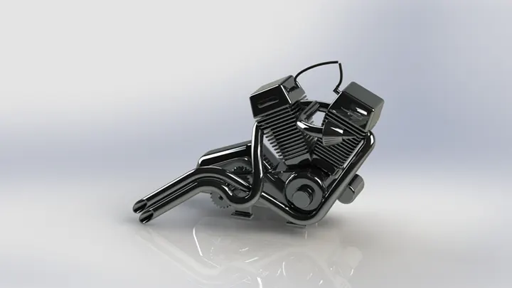
An engine or motor is a machine designed to convert one form of energy into mechanical energy. Heat engines, like the internal combustion engine, burn a fuel to create heat which is then used to do work. A motorcycle engine is an engine that powers a motorcycle. Motorcycle engines are typically two-stroke or four-stroke internal combustion engines. Most engines have a gearbox with up to six ratios. The rider changes gears on motorcycles using a foot-pedal and manual clutch, but early models had hand-levers. More recently, some have automatic or semi-automatic gearboxes.
COMMANDS USED TO MODEL
In Sketch
- Sketch Pictures
- Line
- Circle
- Arc
In Features
- Composite Curve
- Circular Pattern
- Extruded Boss/Base
- Revolved Boss/Base
- Fillet
- Revolved Boss/Base
- Reference Geometry
- Dome
- Mirror
- Extruded Cut
- Combine
- Split
- Chamfer
MODELLING PROCEDURE
- The Blueprint of the sketch was added using insert sketch pictures option on the front plane.
- By using the blueprint the required sketch was drawn and extruded using Extruded Boss/Base and proper fillets were applied.
- Then a plane was created using Reference Geometry and the transmission system were created for placing the Transmission belt using Revolved Boss/Base, Extruded Boss/Base, Extruded Cut, Chamfer and Circular Pattern. Then the fillets and dome were applied on the required area.
- For creating the cylinders of the engine the Extruded Boss/Base were used and dome feature was used to create the dome on the either sides of the cylinder.
- For creating the cooling fins Linear Pattern was used and the other half was mirrored along with the fins and domes.
- The Air Inlet Ducts were designed using Circular Pattern, Extruded Cut and Revolved Boss/Base.
- For creating the Exhaust Pipes Composite Curve feature were used on the reference plane which needs to be created on the face of the engine cylinder.
- By using Swept Boss/Base the exhaust pipes were created and finally Split option were used to cut the unwanted part.
- Then the Spark Plugs were made using Extruded Boss/Base and Swept Boss/Base.
- Finally the part was saved by adding appropriate appearances.
13.FUEL TANK / GAS TANK
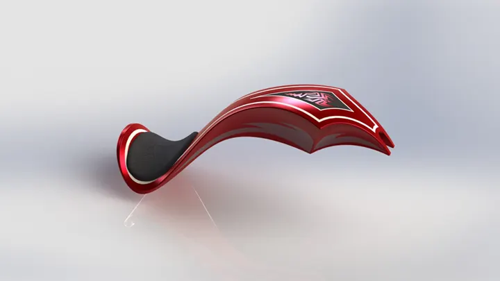
A fuel tank (also called a petrol tank or gas tank) is a safe container for flammable fluids. Though any storage tank for fuel may be so called, the term is typically applied to part of an engine system in which the fuel is stored and propelled (fuel pump) or released (pressurized gas) into an engine. The fuel tank is a reservoir that holds the fuel supply and helps maintain its temperature at a level below its flash point. The fuel tank also serves as an important means of dissipating heat from the fuel that is returned from the engine.
COMMANDS USED TO MODEL
In Sketch
- Sketch Picture
- Spline
- Arc
In Surfaces
- Extruded Surface
- Swept Surface
- Knit Surface
- Surface Boundary
- Surface Trim
- Lofted Surface
In Features
- Project Curve
- Mirror
- Fillet
- Extruded Cut
- Shell
MODELLING PROCEDURE
- First the underlay image of the chopper was added using insert sketch pictures.
- Then a plane was created with respect to the front plane and a sketch was drawn and swept using Swept surface feature and by using the Surface Trim tool the required shape of the Fuel Tank was achieved.
- Then by creating another plane a projected curve was drawn and then by using the curve the surface loft was created using Lofted Surface tool.
- One more plane was created and another curve was projected and Boundary Surface tool were used to create a surface of the fuel tank.
- The other half was mirrored and both the halves were joined at an edge by using Knit Surface tool.
- Then Split Line was used to create the sketch for the seat and Surface Extrude option were used to create the solid body of the seat. Proper fillet were added to get a smooth edges for the seat.
- For placing the fuel tank over the top tube of the Frame a tube shaped portion were removed using Boundary Surface, Lofted Surface, Knit Surface and Swept Cut tools.
- Finally the proper fillets were added along the edges of the fuel tank and a shell was created inside the fuel tank using Shell command.
- By applying an appropriate appearance the part was saved.
ASSEMBLY
Combining multiple parts that fit together to create assemblies is called ASSEMBLY in SOLIDWORKS. We integrate the parts in an assembly using Mates, such as Concentric and Coincident. Mates define the allowable direction of movement of the components.
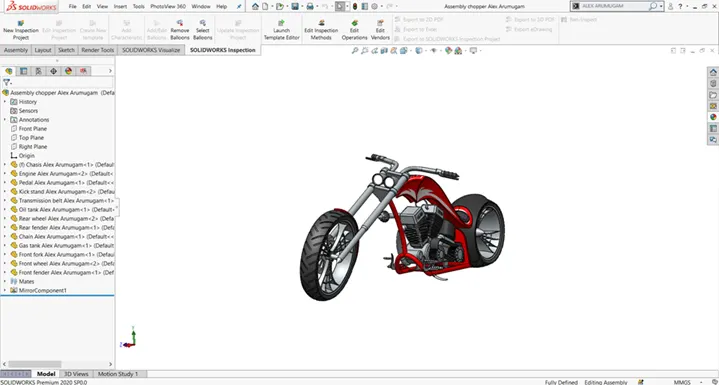
Assembly Definition - An assembly is a collection of related parts saved in one SOLIDWORKS document file with a .sldasm extension.
Assemblies
- Contain anywhere from two to over one thousand components, which can be parts or other assemblies called subassemblies
- Display movement between related parts within their degrees of freedom.
The components in an assembly are defined in relation to each other using assembly mates. The assembly components were attached using various types of mates such as coincident, concentric, and distance mates.
Mates
Mates position the components in an assembly precisely with respect to each other. Positioning the components defines how they move and rotate with respect to each other. Mates create geometric relations, such as coincident, perpendicular, and tangent. Each mate is valid for specific combinations of geometry such as cones, cylinders, planes, and extrusions.
Explode the Assembly
An exploded view separates the components in an assembly to facilitate viewing. Exploded views include many options such as which components to include, what distances to use, and in which direction to display the exploded components. The exploded view is saved with a configuration of the assembly or subassembly.
Assembly Design Methods
Bottom-up Design
In bottom-up design, we create parts, insert them into an assembly, and mate them as required by our design. Bottom-up design is the preferred technique when we use previously constructed, off-the-shelf parts. An advantage of bottom-up design is that because components are designed independently, their relationships and regeneration behavior are simpler than in top-down design. Working bottom-up allows us to focus on the individual parts. It is a good method to use if we do not need to create references that control the size or shape of parts with respect to each other.
Here in American chopper we use bottom up design hence the chopper is previously constructed model and in this project our chopper is designed as a custom model.
Top-down Design
In top-down design, we start our work in the assembly. We can use the geometry of one part to help define other parts, to create features that affect multiple parts, or to create machined features that are added only after the parts are assembled. For instance, we can start with a layout sketch or define fixed part locations, then design the parts referencing these definitions. Top-down design is also known as in-context design. Combination of both the methods were also be used to create an assembly or subassemblies.
In-Context Design
We can create a new part within an assembly document (in the context of an assembly). In addition to creating or editing components in their own part windows, the SOLIDWORKS software lets us to create or edit components in the assembly window. The advantage is that we can reference the geometry of one component to create or modify another component. By referencing the geometry of another component, we ensure that the components fit together correctly. This method of design is called top-down or in-context design because we are working in the context of the assembly.
RENDERING
Rendering of the Solidworks model is done using PhotoView 360 and Solidworks Visualize.
PhotoView 360 is a visualization and rendering solution included with SOLIDWORKS. Providing a highly interactive environment for viewing designs as well as for creating photo-realistic renderings it can be used to showcase our designs.
SOLIDWORKS Visualize (formerly known as Bunkspeed) provides a suite of standalone software tools that combine industry-leading rendering capabilities with visual design-oriented features and workflows, allowing easy and fast creation of visual content that communicates a design's vision, passion, and emotion.
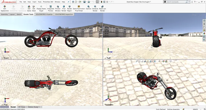
PhotoView 360
PhotoView 360 is distinguished from RealView in that it is not a process of the GPU, and photorealistic renderings can be achieved regardless of the graphics card used. This is because it is entirely calculated on the CPU on your PC and is rendered in a sequential event and is therefore not dynamic. PhotoView 360 renderings are more photorealistic than RealView because light rays and reflections are more accurately calculated.
PhotoView 360 rendering supports:
- Self-reflection (reflection of objects in one another)
- HDRI (environmental) lighting.
Appearances
Appearances control the way the surfaces of the model look. They can be applied at the assembly, part, body, feature or face of a model. All surface of a model have an appearance applied to them.
Materials vs Appearances
Appearances are different from materials. When we applied a material to a part, it defines the physical properties of the part such as density and strength. Included in the material definition is a default appearance, however this can be changed. As an example, if we were modeling a body component for an automobile, the material would be steel, however the final component would be painted, so the appearance could be something other than what was applied with the steel material.
Photorealistic Rendering
Photorealistic rendering is the process of photography except that we are using a computer model instead of a physical model. Prior to actually producing a product we may need to show the customer what the product will look like or we may need to produce marketing materials.
The PhotoView 360 software
PhotoView 360 is a software solution from Solidworks, fully integrated into the Solidworks software to create photorealistic images directly from Solidworks models. Renderings may be created from Solidworks parts and assemblies, but not drawings. PhotoView 360 can produce photorealistic images to add visual impact to presentations and documents.
Some of the key features of PhotoView 360 are:
- Photorealistic images directly from Solidworks models
- PhotoView 360 interacts with the 3D geometry created with the Solidworks software. All changes to Solidworks models are accurately represented in the PhotoView 360 images.
- Fully integrated into Solidworks.
- PhotoView 360 software is supplied as a Solidworks add-in.
Appearances in PhotoView 360
Appearances affect the way a surface reacts to light. They may be applied to parts, features or faces.Appearances are of two general types,
Procedural Appearances
Procedural appearances are defined by some procedure and consist of one or more colors and the way the appearance reacts to light. Procedural appearances can be thought of as 3D, that is they go all the way through the part. This is like adding dye to a plastic to be injected; the color will go all the way through the finished part.
Texture Appearances
Texture appearances are applied like wallpaper. During application, they can be stretched, shrunk, rotated, and reoriented to make them fit the surface. The pattern will be duplicated as many times as necessary to cover the entire surface.
Lighting
Lights may be added in the same way a photographer adds lights when taking photographs. PhotoView 360 uses the same lights as SolidWorks but also uses lighting from the rendering environment or scene. PhotoView 360 has the sophistication to trace light rays and reflections.
Scenes
Each SolidWorks model is associated with a PhotoView 360 scene, for which you can specify properties such as environments and backgrounds. Scenes help to put products in context.
Decals
Images, such as company logos, can be applied to models.
Output
The rendered output from PhotoView 360 can be viewed on the screen, or saved to a graphics file.
Options
PhotoView 360 has its own options. Options allow you to customize the PhotoView 360 settings to reflect your preferences. Options are divided into Output Image Settings, Render Quality, Bloom, Contour Rendering and Direct Caustics.
Scenes
PhotoView 360 scenes are made up of the things we see in the rendering that are not the model. They can be thought of as a virtual sphere around the model. Scenes are composed of backgrounds, foreground effects, and scenery. PhotoView 360 has numerous predefined scenes to make initial renderings quick and easy.
PHOTOVIEW OF THE CHOPPER
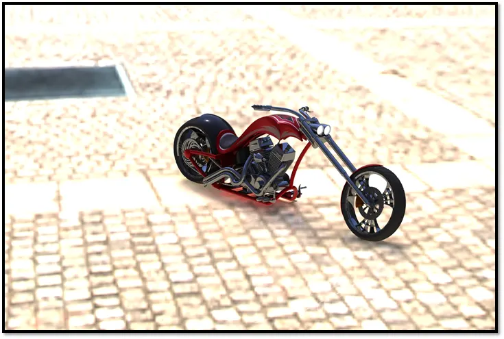
PhotoView 360 Rendering Procedure
For each SolidWorks model to be rendered, the process requires the same steps. Most of the steps are done within SolidWorks with only a few steps requiring PhotoView 360.
The following steps are repeated until a satisfactory output is obtained:
- Position the Model - Use a standard view, or use zoom, rotate and move to position the model in the desired position.
- Apply appearances to the model, features and/or selected faces.
- Set the Scene - Select one of the various preset scenes, or set your own background and scenery.
- Set Lighting - Adjust the environmental lighting or add direct lights. Preview Render The preview is a test of the settings before final render.
- Render the Model - The model is rendered to the Final Render window.
- Save Output - To be used, the final render must be saved as a separate image file.
- Post Processing - The rendered image output is not always the final product. Often the image output is used with other programs for additional effects.
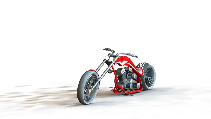
SOLIDWORKS Visualize
Quickly and easily create professional, photo-quality images, animations, and other interactive 3D content to get your products to market faster.
SOLIDWORKS Visualize allows us to leverage our 3D CAD data to create photo-quality content in the fastest and easiest way we can–from images to animations, interactive web content, and immersive Virtual Reality. It brings our products to life. SOLIDWORKS Visualize is the “camera” for our CAD data.
Some renderers are fast but output low-quality images. Some produce great quality but take six months to learn. Others are easy to use, but take four hours to render an image. SOLIDWORKS Visualize provides the right combination of quality, speed, and ease of use, and is the best renderer.
SOLIDWORKS VISUALIZE PROFESSIONAL
With SOLIDWORKS Visualize Professional we can tell a deeper 3D story about our product using our CAD data. It enables us to easily generate photo-quality stills and interactive animations to effectively communicate the most complex design details.
The features of SOLIDWORKS Visualize Professional are listed below,
- Demonstrate products more effectively with full animation of parts, models, appearances, cameras, and environments
- Import our SOLIDWORKS CAD Motion Studies for truly photographic animations
- Quickly show off the final design with one-click 360-degree spins
- Create interactive web content such as Interior Panoramas and Exterior VRs
- Present and compare varying design solutions side-by-side with multiple viewports and included Configurator tool
- Unleash our creative side with customizable Camera Filters
SOLIDWORKS Visualize Professional also includes key features to help increase productivity. The integrated Render Queue allows us to stack up jobs on our machine or a dedicated render farm to automatically complete one after the other, providing remarkable time savings.
Full Animation Suite (parts, models, appearances, cameras & environments)
- Simple one-click 360 degree turntable animations make this type of output a breeze to create.
- Part/Group/Model animations for animated exploded views, sequence animation, and more to explain complex mechanical movements and detailed designs.
- Camera animations with unique Animation Ribbon, which is an intuitive 3D representation of how the camera moves through the scene, making camera flys a snap to create.
- Sun Study output type allows Visualize users to see what the play of light looks like across their model throughout an entire day. This is perfect for interior designers who need to see how sunlight casts shadows from their interior concept throughout a complete day sun-cycle.
Custom camera Post-Processing (camera filters)
Unleash our creativity and add additional effects to your Visualize content with customizable camera filters and the new Bloom Filter, perfect for glowing LEDs, lights and sun highlights.
Render Queue
Similar to a printer queue, stack up render jobs to send all at once, for example at the end of the day, to remain productive during work hours and allow all the renders to cook overnight. The integrated Render Queue instantly boosts productivity allowing us to never wait for a render to finish again.
Procedure for creating visualization
With its simple, intuitive user interface, SOLIDWORKS Visualize requires virtually no learning curve and lets users produce content quickly. Even non-technical staff can start creating amazing content instantly.
- Create new project by importing the required assembly or models into the Solidworks Visualize
- Add the required appearance, environments, backplates and lights
- By using the camera tool position the designed model in a realistic view
- Make sure that the model touches the floor. It can be achieved by using snap to the floor option on Models
- By applying the required settings the required outputs can be rendered using output tool
RENDERED IMAGES OF THE CHOPPER
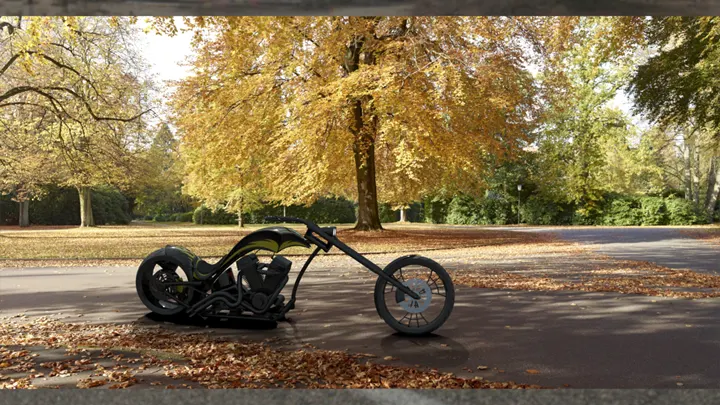
VISUALIZED ON THE HIGHWAY
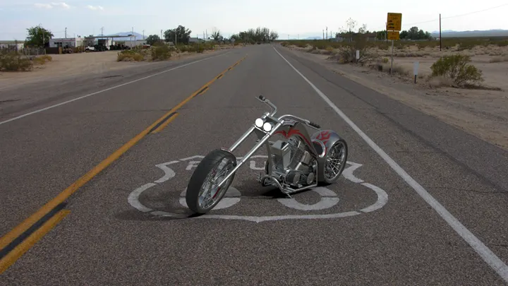
VISUALIZED IN A STREET
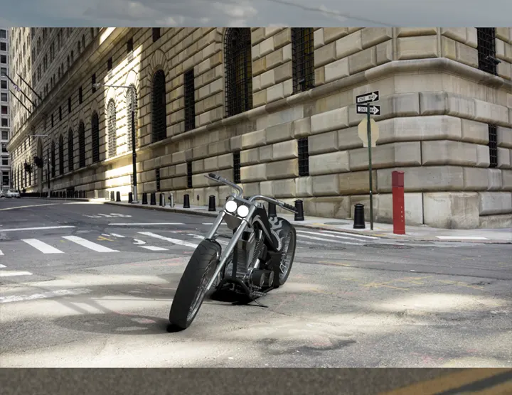
VISUALIZED ON THE RED SAND ENVIRONMENT
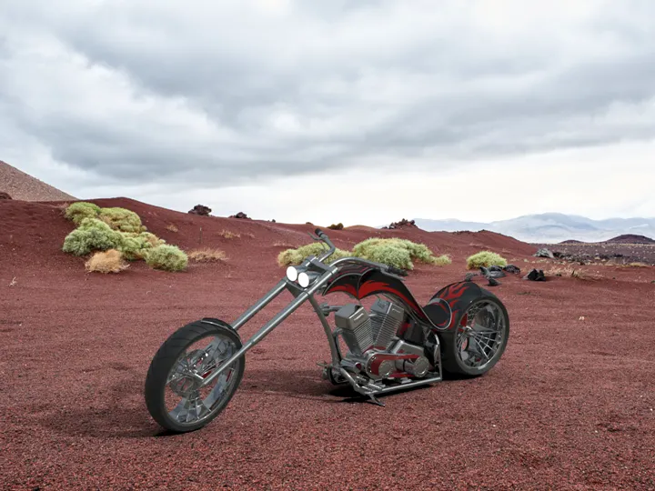
VISUALIZED OVER THE DOCKTOWN BRIDGE
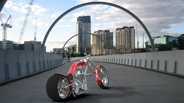
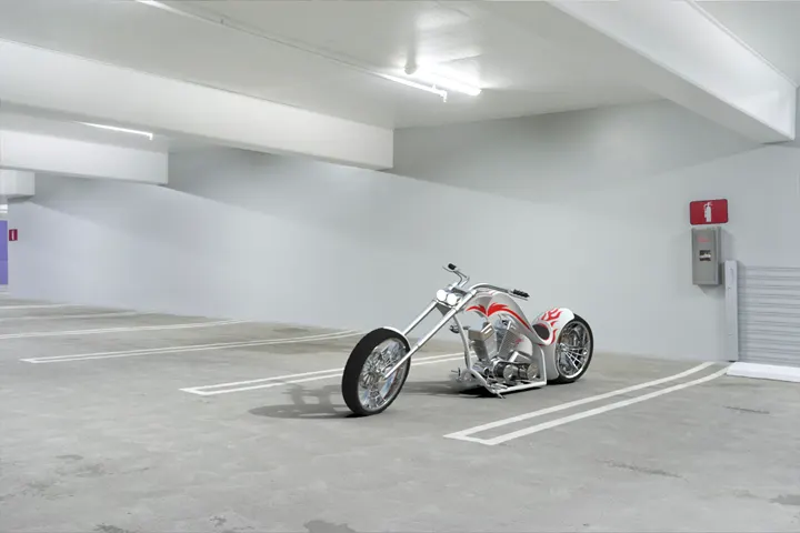
VISUALIZED IN A MODERN GARAGE
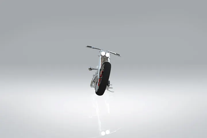
FRONT VIEW OF THE CHOPPER
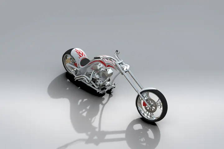
ISOMETRIC VIEW OF THE CHOPPER
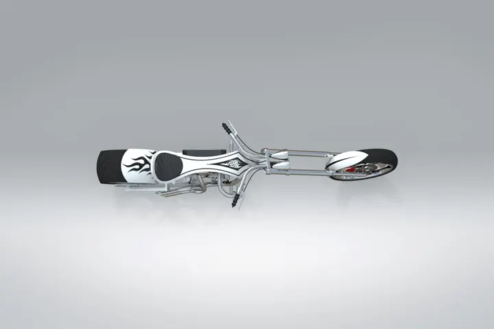
TOP VIEW OF THE CHOPPER
Conclusion
Thus the project Design and Assembly of American Chopper Bike with photo realistic rendering using SOLIDWORKS has been created and completed successfully.