Designing a Steam Locomotive with Southern Valve Gear
Designing a Steam Locomotive – The Flying Scotsman with Southern Valve Gear
OBJECTIVE
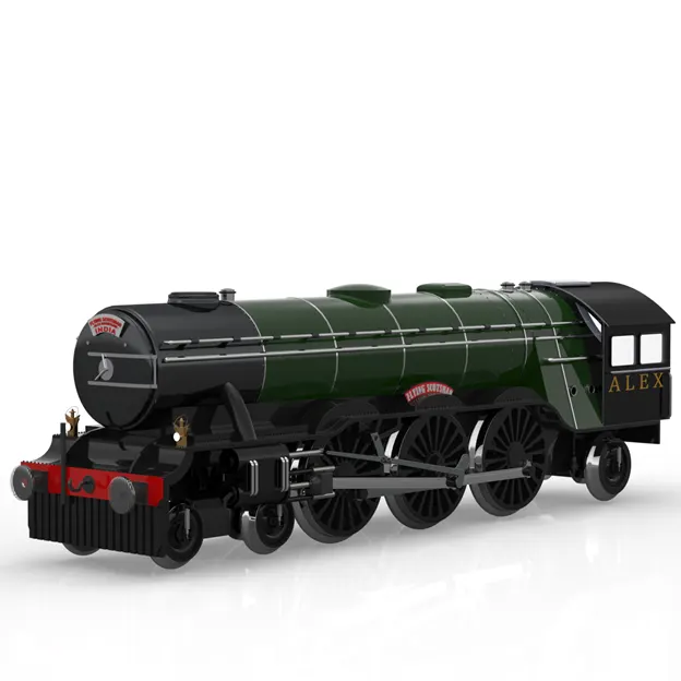
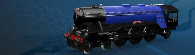
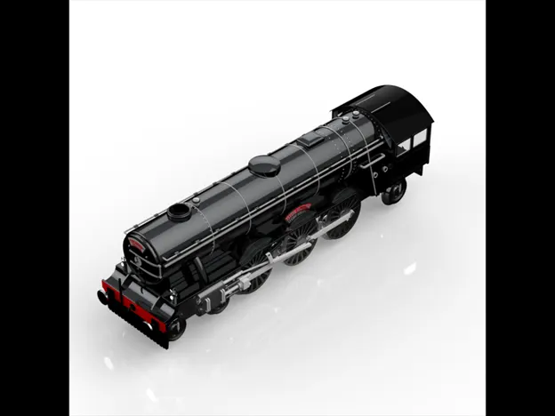
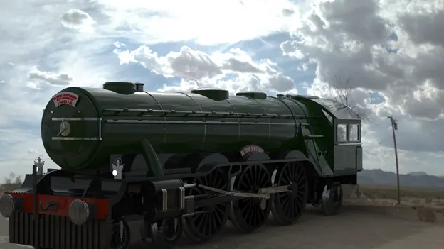
The objective of the project is to design a Steam Locomotive – The Flying Scotsman by replacing the Walschaerts Valve Gear system with the Southern Valve Gear system independently. The designed dynamic model should have the fully functional valve gear system. Then the designed model should be rendered to get a photo realistic render of the locomotive.
INTRODUCTION
In this project the famous American Steam Locomotive – The Flying Scotsman was designed with the fully functional Southern Valve Gear system. The real life Flying Scotsman uses the Walschaerts Valve Gear System to drive but in this model the Walschaerts Valve Gear System was replaced with the Southern Valve Gear.
The valve gear of a steam engine is the mechanism that operates the inlet and exhaust valves to admit steam into the cylinder and allow exhaust steam to escape, respectively, at the correct points in the cycle. It can also serve as a reversing gear. It is sometimes referred to as the "motion".
For modeling the Locomotive the computer aided design software SOLIDWORKS was used. The SOLIDWORKS is a mechanical design automation application that lets designers quickly sketch out ideas, experiment with features and dimensions, and produce models and detailed drawings.
For rendering the SOLIDWORKS Visualize was used. It is a photo-realistic rendering tool that utilizes our CAD data to create magazine quality images or commercial quality animations.
DESIGN PROCESS
- Define the Problem
We can’t find a solution until we have a clear idea of what the problem is.
- Collect Information
Collect sketches, take photographs and gather data to start giving us inspiration.
- Brainstorm and Analyze Ideas
Begin to sketch, make, and study so we can start to understand how all the data and information we’ve collected may impact our design.
- Develop Solutions
Take our preliminary ideas and form multiple small-scale design solutions.
- Gather Feedback
Present our ideas to as many people as possible: friends, teachers, professionals, and any others we trust to give insightful comments.
- Improve
Reflect on all of our feedback and decide if or to what extent it should be incorporated. It is often helpful to take solutions back through the Design Process to refine and clarify them.
DESIGN REQUIREMENTS
The essential requirements of a good product design are listed as follows:
- Product must optimally perform its main function.
- It must be easy to repair at a low repair cost.
- It must be very reliable to use.
- It must follow principles of aesthetics.
- It must be a durable one.
- It can be easily produced in large numbers at minimum production cost.
- It must be simple to produce and use (handle).
- It must also be compact.
DESIGN INTENT
The intent of the project is to design a Steam Locomotive with a fully functional valve gear system. In this project the famous American Steam Locomotive – The Flying Scotsman was designed as a dynamic model. The real life Scotsman with the Walschaerts Valve Gear must be replaced by the Southern Valve Gear.
DESIGN APPROACH
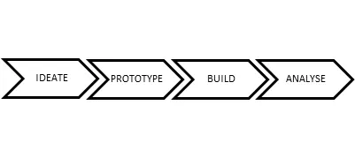
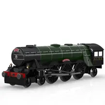
DESIGN METHODOLOGY
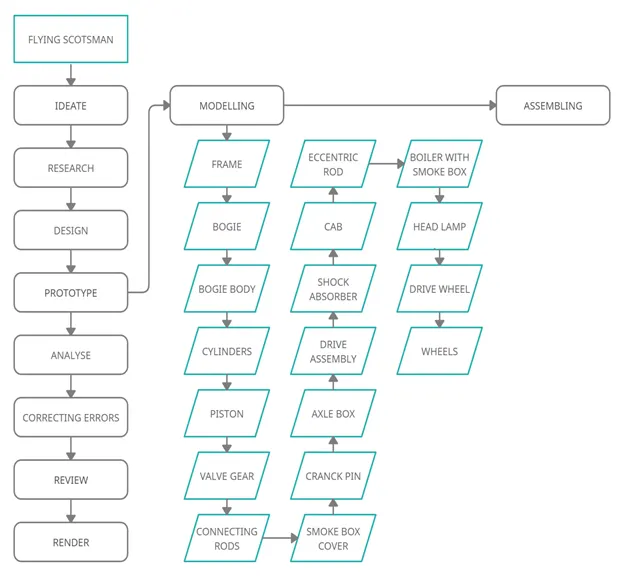
DOUBLE CRANCK MECHANISM
In a four bar linkage, if both of the side links revolve, it is called a double-crank mechanism. As the name implies, there will be two cranks present in the four-bar chain mechanism. In a locomotive application, the wheels will be connected with a connecting rod as shown in the below picture.
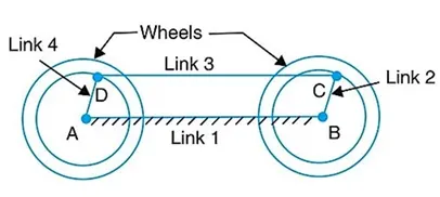
In this Mechanism, there are 2 links (AD, BC (equal lengths) acts as the cranks, and the one link(CD) acts as the connecting rod or coupling rod. and one link(AB) is fixed.
The Steam Locomotive of this project has a fully functional rotating wheels which was achieved by using the Double Crank Mechanism.
SLIDER CRANCK MECHANISM
Slider-crank mechanism, arrangement of mechanical parts designed to convert straight-line motion to rotary motion, as in a reciprocating piston engine, or to convert rotary motion to straight-line motion, as in a reciprocating piston pump.
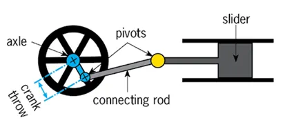
The piston present inside the cylinder helps the locomotive to move by accelerating the drive wheels by using the steam generated by the boiler which was achieved by using Slider crank mechanism.
WALSCHAERTS VALVE GEAR SYSTEM
The Walschaerts valve gear was slow to gain popularity. The Stephenson valve gear remained the most commonly used valve gear on 19th-century locomotives. However, the Walschaerts valve gear had the advantage that it could be mounted entirely on the outside of the locomotives, leaving the space between the frames clear and allowing easy access for service and adjustment, which resulted in it being adopted in some articulated locomotives.
The Walschaerts valve gear is an improvement on the earlier Stephenson valve gear in that it enables the driver to operate the steam engine in a continuous range of settings from maximum economy to maximum power.
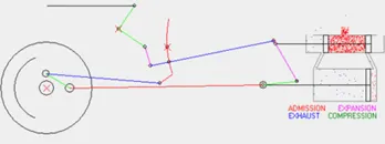
At any setting, the valve gear satisfies the following two conditions:
- The valve opens to admit steam to the cylinder just before the start of a piston stroke. The pressure of this steam provides the driving force.
- Soon before the space on one side of the piston starts to contract, the valve starts to release steam from that space to the atmosphere, so as not to impede the movement of the piston.
In an economical setting, steam is admitted to the expanding space for only part of the stroke; at a point set by the driver, the intake is cut off. Since the exhaust is also shut, during the rest of the stroke the steam that has entered the cylinder expands in isolation, and so its pressure decreases. Thus, the most energy available from the steam (in the absence of a condenser) is used.
The Walschaerts valve gear enables the engine driver to change the cutoff point without changing the points at which intake starts.
SOUTHERN VALVE GEAR SYSTEM
Unlike the Walschaerts and Baker systems, the Southern valve gear dispensed with the combination lever which transmitted some of the crosshead motion to the valves. As with those systems it used a return crank on a driver (instead of the eccentrics used by the Stephenson valve gear). The return crank attached to the eccentric rod, which hung from a pivot close to the far end of the eccentric rod. This pivot attached to the end of the radius hanger, the other end of which attached to a link block which slid back and forth in a track curved in the same manner as the expansion link of a Walschaerts gear. In this system, however, the track was fixed in place; sliding the link block back and forth controlled reversing and cutoff.
At the end of the eccentric rod, close to the radius hanger, the rod connected to the transmission yoke. The upper end of this rod connected to a bell crank, which translated the up and down motion of the transmission yoke into back and forth motion of the valves.
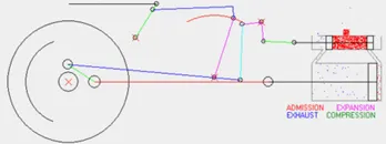
The mechanism is a little less obvious than that of the other types, but control is fundamentally like that of the Baker system. In this case the controlling factor is the angle between the radius hanger and the transmission yoke; when they are parallel, there is little up-down motion of the transmission yoke and the engine is centered. As link block moves back and forth, the angle of the radius hanger changes, and the up and down motion of the transmission yoke in response to the back and forth motion of the eccentric rod is increased or decreased.
BENEFITS OF USING SOUTHERN VALVE GEAR SYSTEM
The valve rod and piston was not connected as of in walschaerts valve gear system so that,
- the efficiency of the cycle can be increased.
- compact model so that it is easy to maintain.
DESIGN ANALYSIS
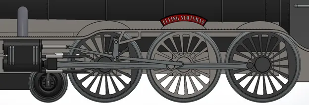
The real life Steam Locomotive runs with the working principle of Walschaerts Valve Gear system. But in my project the Walschaerts Valve Gear system was replaced by Southern Valve Gear system. I have used the working principle of the Southern Valve Gear and made my model having a compact working valve gear system. The compact design was achieved by having a fixed link on the Drive wheels.
3-D MODELLING OF THE STEAM LOCOMOTIVE
BLUEPRINT
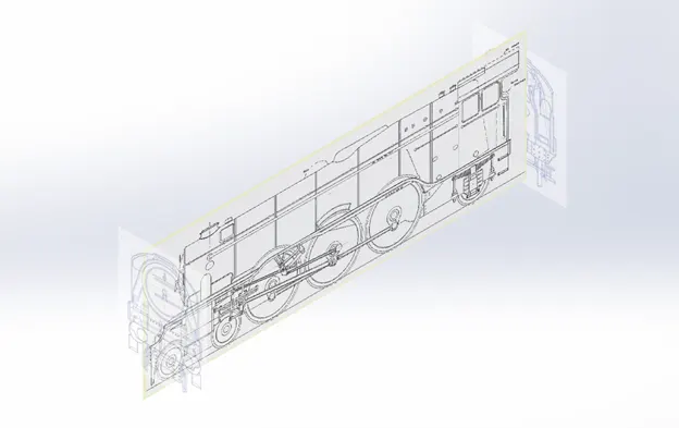
The image from the Classic Projects: LNER Class A3 4472 Flying Scotsman from the Engineering and Technology has been used as a blueprint of my project. By using the insert sketch pictures option the blue print was set successfully.
FRAME
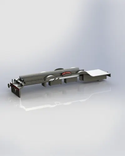
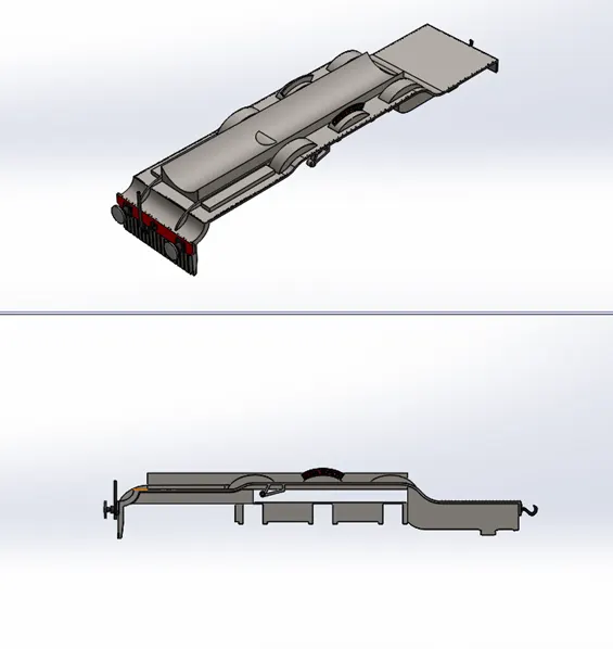
A locomotive frame is the structure that forms the backbone of the railway locomotive, giving it strength and supporting the superstructure elements such as a cab, boiler or bodywork. The vast majority of locomotives have had a frame structure of some kind. The frame may in turn be supported by axles directly attached to it, or it may be mounted on bogies/ trucks, or a combination of the two. The bogies in turn will have frames of their own.
A buffer stop, bumper, bumping post, bumper block or stop block , is a device to prevent railway vehicles from going past the end of a physical section of track.
A coupling (or a coupler) is a mechanism used to connect rolling stock in a train. The design of the coupler is standard, and is almost as important as the track gauge, since flexibility and convenience are maximized if all rolling stock can be coupled together.
DESCRIPTION
- In my model the frame of my locomotive was designed with the bumper, name plate, front and rear hooks (also called as Coupling).
- The frame of the locomotive was modeled using the following commands, Extruded Boss/Base, Extruded Cut, Fillet, mirror, Linear Pattern and Split command.
- The frame was designed to have every components mated to it by fixing the frame with the respected Assembly planes.
- All other components were mated with respect to the frame.
BOGIE
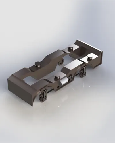
A bogie is a chassis or framework that carries a wheel set, attached to a vehicle a modular subassembly of wheels and axles. Bogies take various forms in various modes of transport.
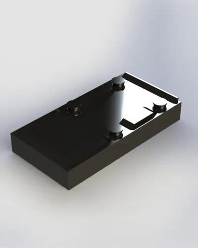
DESCRIPTION
- The bogie of my model was designed using Extruded Boss/Base, Extruded Cut, Swept Boss/Base, Mirror, Reference Plane and fillet commands.
- The bogie part was set in front of the frame above the front wheel truck of the locomotive.
BOGIE FRAME
The Bogie frame is an important and integral member of bogie. The bogie is known as the wagon’s movement system. The bogie frame is either casted or fabricated. The bogie frames are manufactured based on its working conditions. It is the main component which takes the stresses.
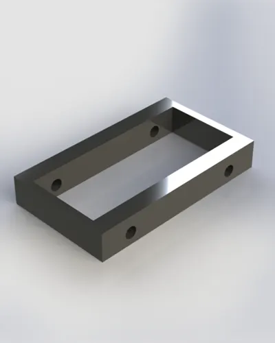
DESCRIPTION
- The Bogie frame is designed to set the wheel set along with the axles.
- It was designed using Extruded Boss/Base and Extruded Cut.
DRIVE WHEELS
On a steam locomotive, a driving wheel is a powered wheel which is driven by the locomotive's pistons. On a conventional, non-articulated locomotive, the driving wheels are all coupled together with side rods (also known as coupling rods); normally one pair is directly driven by the main rod (or connecting rod) which is connected to the end of the piston rod; power is transmitted to the others through the side rods.
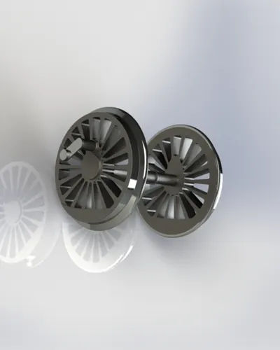
DESCRIPTION
- The drive wheels of my locomotive was designed by using Revolved Boss/Base, Extruded Boss/Base, Extruded Cut, Offset, Mirror, Fillets and Reference Plane etc.
- The drive wheel was designed to have an extrude on the outer sides of the wheel which helps the Valve Gear System to work perfectly.
- The wheels have separated by adding different appearance.
WHEEL SET
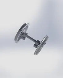
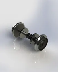
A wheel set is the wheel–axle assembly of a railroad car. The frame assembly beneath each end of a railcar or locomotive that holds the wheelset is called the bogie. Most North American freight cars have two bogies with two or three wheelset, depending on the type of car, short freight cars generally have no bogies but instead have two wheel set.
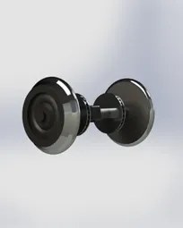
DESCRIPTION
- The wheel set was used on the front and back portion of the locomotive for railing.
- The wheels were designed to have two discs on its axle for braking purpose.
- It was also designed along with the axles as a complete set.
- For designing the wheel set the following commands were used Revolved Boss/Base, Extruded Boss/Base, Mirror, Fillets and Reference Planes.
AXLE BOX
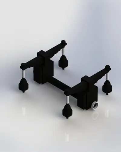
The axle box is the device that allows the wheel set to rotate by providing the bearing house and also the mountings for the primary suspension to attach the wheel set to the bogie or vehicle frame. The axle box transmits longitudinal, lateral and vertical forces from the wheel set on to the other bogie elements. From a vehicle dynamic behavior point of view, axle boxes with plain bearings had certain positive features.
DESCRIPTION
- The Axle Box was positioned for the rear wheels which supports the shock absorption and the brakes for the locomotive.
- To design the Axle Box the following commands were used, Extruded Boss/Base, Extruded Cut, Swept Boss/Base, Split, Reference Plane, Mirror and fillets.
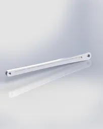
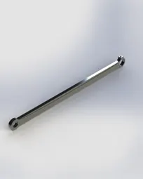
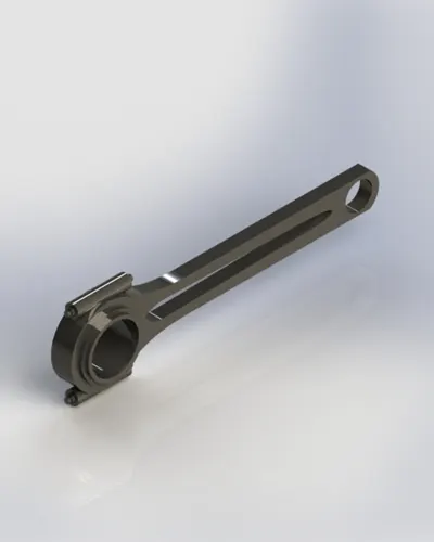
CONNECTING RODS
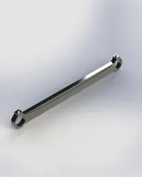
A connecting rod, also called a con rod, is the part of a piston engine which connects the piston to the crankshaft. Together with the crank, the connecting rod converts the reciprocating motion of the piston into the rotation of the crankshaft. The connecting rod is required to transmit the compressive and tensile forces from the piston, and rotate at both ends.
In a steam locomotive, the cranks are usually mounted directly on the driving wheels. The connecting rod is used between the crank pin on the wheel and the crosshead (where it connects to the piston rod). The equivalent connecting rods on diesel locomotives are called 'side rods' or 'coupling rods'.
DESCRIPTION
- I have modeled various connecting rods at different sizes to achieve a fully functional Valve Gear Systems.
- There are many connecting rods required for my locomotive so I have shown some variations in modeling the connecting rods.
- The connecting rods were also designed to avoid the intersections between them while moving.
- The piston of the locomotive was directly connected to the drive wheels.
- The main connecting rods size was founded by using Double Crank Mechanism.
ECCENTRIC RODS
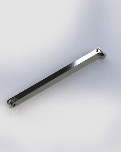
It is used most often in steam engines, and used to convert rotary into linear reciprocating motion to drive a sliding valve or pump ram. An attached eccentric rod is suspended in such a way that its other end can impart the required reciprocating motion.
Description
- The eccentric rods has its own mechanism and its purpose of function. It helps the valve rod to function as per the cycles.
- To achieve a perfect cycle in inlet and outlet of steam inside the cylinder by Valves the rod must be perfect in size.
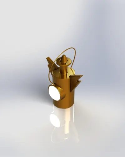
HEAD LAMP
The main purpose of the headlamp is that it can warn people on the track ahead of an approaching train, and with sufficient time for them to take evasive action. The other main benefit is the ability to light up whistle posts and landmarks.
DESCRIPTION
- The head lamp was designed by using Dome, Swept Boss/Base, Extruded Boss/Base, Offset and Fillets.
- The head lamp was placed before the smoke box.
- Since the motto of my project was to design an old steam locomotive the head lamp was designed as an old fashioned one.
PISTON
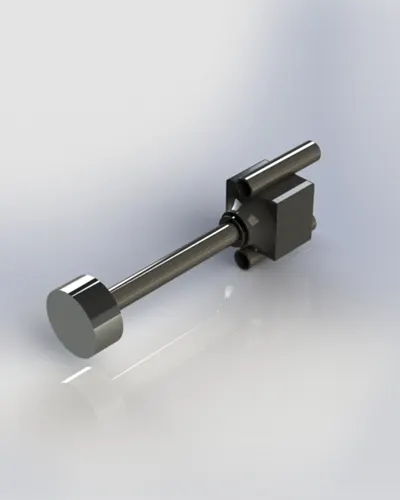
Piston valves are one form of valve used to control the flow of steam within a steam engine or locomotive. They control the admission of steam into the cylinders and its subsequent exhausting, enabling a locomotive to move under its own power.
DESCRIPTION
- The Piston was designed to produce the circular motion by converting the linear motion.
- The length of the Piston need to be accurate for smooth rotation of wheels.
- It uses the Steam generated from the boiler to move front and backward within the cylinder for transferring the energy to the wheels.
VALVE GEAR
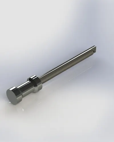
The valve gear of a steam engine is the mechanism that operates the inlet and exhaust valves to admit steam into the cylinder and allow exhaust steam to escape, respectively, at the correct points in the cycle. It can also serve as a reversing gear. It is sometimes referred to as the "motion".
DESCRIPTION
- The Valve Rod was used to function the inlet valve and exhaust valve in which the steam passes through to make the piston works intermittently.
- The valve rod was designed by using the exact dimensions of the cylinders and connecting rods.
CYLINDERS
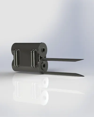
The cylinder is the power-producing element of the steam engine powering a steam locomotive. The cylinder is made pressure-tight with end covers and a piston; a valve distributes the steam to the ends of the cylinder. Cylinders were cast in iron and later made of steel.
Piston valves are one form of valve used to control the flow of steam within a steam engine or locomotive. They control the admission of steam into the cylinders and its subsequent exhausting, enabling a locomotive to move under its own power.
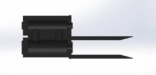
DESCRIPTION
- The Cylinders of the locomotive was designed to have two pathways inside in which the steam passes through for forward and backward movement of piston.
- The Cylinders were designed to have pipes which connects the valve cylinder and the Piston cylinder.
- The purpose of the cylinder was to regulate the pressure inside the cylinders.
- For the movement of piston the cylinders were connected together and designed to have a shaft outside.
CAB
The cab, crew compartment or driver's compartment of a locomotive is the part housing the train driver/engineer, fireman or second man/assistant (if any), and the controls necessary for the locomotive/self-propelled rail vehicle's operation.
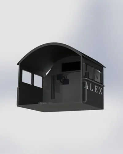
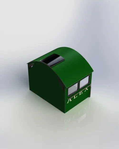
DESCRIPTION
- The Cab was fully Designed by using the Surface feature in Solid works.
- The commands used to model the Cab are Extrude Surface, Trim Surface, Filled Surface, Lofted Surface, knitted Surface and Fillets.
- For creating the hand support and windows some of the solid feature commands also used such as Extruded Boss Base, Extruded Cut, Swept Boss/Base.
- Inner side of the cab was designed to have a display for monitoring and some pipes for regulating the steam pressure and levers for controlling the brakes of the locomotive.
BOILER WITH SMOKE BOX
The Locomotive Boiler is a fire tube boiler. It is a device that is used to create steam from water by using heat energy. A locomotive boiler is a device that is used to create steam from water by using heat energy. This is a horizontal drum axis, multi-tubular, natural circulation, artificial draft, forced circulation, medium pressure, solid fuel fired fire tube boiler that has an internal fire furnace. The main function of it is to generate high steam rate because of that we see the grate area of this type of boiler is quite big also it has a number of fire tubes for improving the steam producing rate.
Smoke Box is a box in which the smoke of the burnt fuel after passing through the fire tubes gets collected and From there it is exhausted in the environment by the chimney.
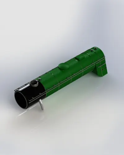
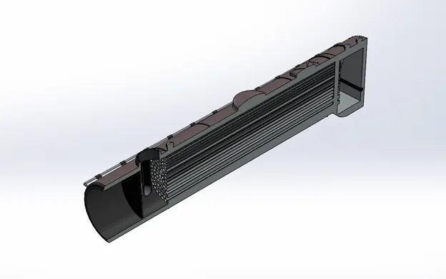
DESCRIPTION
- The Boiler and Smoke box both were designed as attached since the major idea of the project was to perform the valve gear system.
- The boiler was designed to have steam tubes inside to transfer the heat from the Burner.
- The burned exhaust waste was collected inside the smoke box which was cleaned periodically by removing the Smoke Box Cover.
- The Boiler was also designed to have two domes on top, one for filling of water and the other one has sand which will be use full in wet rail condition to increase the grips of the wheels.
SMOKE BOX COVER
Ashes and soot which may be present in the smoke are often deposited in the smoke box. The front of the smoke box has a door which is opened to remove these deposits at the end of each locomotive's working day. The handle(s) must be tightened fully to prevent air leaks, which would reduce the draw on the fire and can also allow any un burnt char at the bottom of the smoke box to catch fire there. Some smoke box doors have a single handle in the form of a wheel; many British-built locomotives have a pair of smoke box door handles resembling the hands of a clock; other designs also exist. On many steamrollers an extension to the body of the smoke box also houses the bearing which supports the front roller. Due to limitations of space, these rollers usually have a drop-down flap instead of a circular smoke box door.
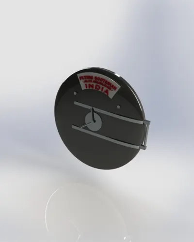
DESCRIPTION
- The Smoke Box Cover was designed to cover the smoke box along with the name plate.
- It was designed to function as a door hinge mechanism.
- The levers designed at the center of the cover was used to lock the Smoke Box Cover.
CRANCK PIN
A crankpin is a mechanical device in an engine which connects the crankshaft to the connecting rod for each cylinder. It has a cylindrical surface, to allow the crankpin to rotate relative to the "big end" of the connecting rod.
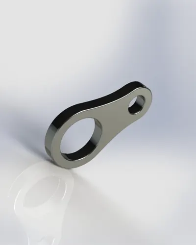
DESCRIPTION
- The Crank Pin was designed to connect the valve rod along with the Drive wheels to complete the cycle perfectly.
- The crank pin modeling was an easy task since it just requires the dimension of the wheel connectors.
ECCENTRIC LINK
In early locomotive practice, the eccentric rod ends were pivoted at the ends of the link while, in marine engines, the eccentric rod pivots were set behind the link slot (or below on a vertical engine). These became known respectively as the 'locomotive link' and the 'launch link'.
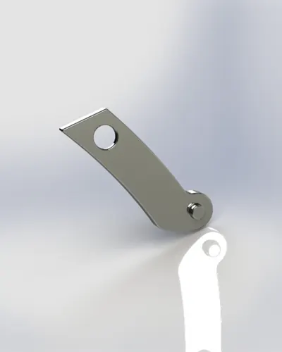
DESCRIPTION
- The eccentric link was designed to support the eccentric rod which fulfills the Southern Valve Gear System and its mounted on the sides of the frame of the locomotive.
- The movement of the locomotive was controlled by adding angle Mates.
SHOCK ABSORBER
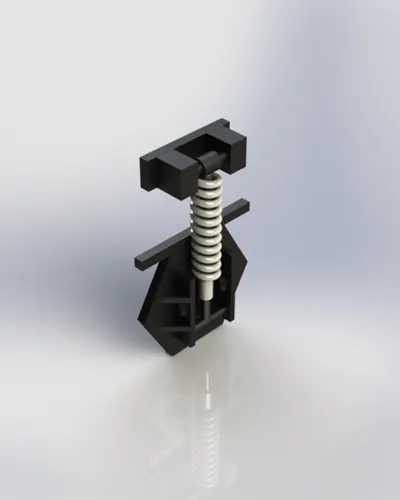
The shock absorbers are used to reduce the effects of vibration occurring as a result of the wheel/rail interface.
DESCRIPTION
- The Shock Absorber was designed as a set which will be mated perfectly along with the axles of the wheels.
- The commands used to model the Shock Absorber was Swept Boss/Base, Helix and Spiral, Revolved Boss/Base, Chamfer, Mirror and Fillets.
DRIVE ASSEMBLY
DESCRIPTION
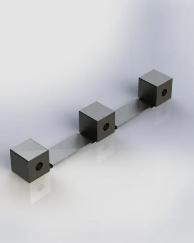
- The drive assembly of the locomotive was designed to fit inside the center portion between the drive wheels.
- Since the project was modeled only by using the LNER Class A3 4472 Flying Scotsman images found from online, the necessary details for modeling the inner portion was lacked.
- To get a perfect model while rendering the required Parts were compiled as drive assembly.
ASSEMBLY
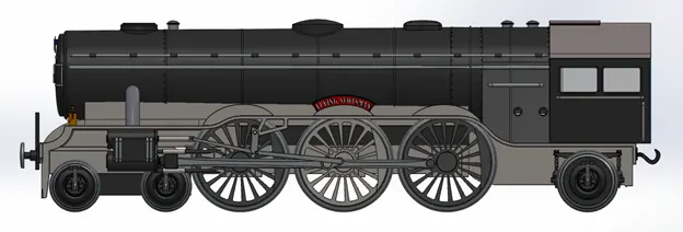
Combining multiple parts that fit together to create assemblies is called ASSEMBLY in SOLIDWORKS. We integrate the parts in an assembly using Mates, such as Concentric and Coincident. Mates define the allowable direction of movement of the components.
Assembly Definition
An assembly is a collection of related parts saved in one SOLIDWORKS document file with a .sldasm extension.
Assemblies
- Contain anywhere from two to over one thousand components, which can be parts or other assemblies called subassemblies.
- Display movement between related parts within their degrees of freedom.
The components in an assembly are defined in relation to each other using assembly mates. The assembly components were attached using various types of mates such as coincident, concentric, and distance mates.
Mates
Mates position the components in an assembly precisely with respect to each other. Positioning the components defines how they move and rotate with respect to each other. Mates create geometric relations, such as coincident, perpendicular, and tangent. Each mate is valid for specific combinations of geometry such as cones, cylinders, planes, and extrusions.
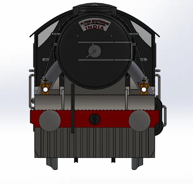
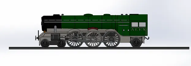
FRONT VIEW
Wheel Alignment
RENDERING
Rendering of the Solid works model is done using Photo View 360 and Solid works Visualize.
Photo View 360 is a visualization and rendering solution included with SOLIDWORKS. Providing a highly interactive environment for viewing designs as well as for creating photo-realistic renderings it can be used to showcase our designs.
SOLIDWORKS Visualize provides a suite of standalone software tools that combine industry-leading rendering capabilities with visual design-oriented features and workflows, allowing easy and fast creation of visual content that communicates a design's vision, passion, and emotion.
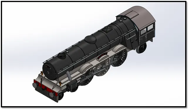
Photo View 360 Rendering Procedure
For each Solid Works model to be rendered, the process requires the same steps. Most of the steps are done within Solid Works with only a few steps requiring Photo View 360.
The following steps are repeated until a satisfactory output is obtained:
- Position the Model - Use a standard view, or use zoom, rotate and move to position the model in the desired position.
- Apply appearances to the model, features and/or selected faces.
- Set the Scene - Select one of the various preset scenes, or set your own background and scenery.
- Set Lighting - Adjust the environmental lighting or add direct lights. Preview Render The preview is a test of the settings before final render.
- Render the Model - The model is rendered to the Final Render window.
- Save Output - To be used, the final render must be saved as a separate image file.
- Post Processing - The rendered image output is not always the final product. Often the image output is used with other programs for additional effects.
SOLIDWORKS Visualize
Quickly and easily create professional, photo-quality images, animations, and other interactive 3D content to get your products to market faster.
SOLIDWORKS Visualize allows us to leverage our 3D CAD data to create photo-quality content in the fastest and easiest way we can–from images to animations, interactive web content, and immersive Virtual Reality. It brings our products to life. SOLIDWORKS Visualize is the “camera” for our CAD data.
Some renderers are fast but output low-quality images. Some produce great quality but take six months to learn. Others are easy to use, but take four hours to render an image. SOLIDWORKS Visualize provides the right combination of quality, speed, and ease of use, and is the best renderer.
Procedure for creating visualization
With its simple, intuitive user interface, SOLIDWORKS Visualize requires virtually no learning curve and lets users produce content quickly. Even non-technical staff can start creating amazing content instantly.
- Create new project by importing the required assembly or models into the Solid works Visualize.
- Add the required appearance, environments, back plates and lights.
- By using the camera tool position the designed model in a realistic view.
- Make sure that the model touches the floor. It can be achieved by using snap to the floor option on Models.
- By applying the required settings the required outputs can be rendered using output tool.
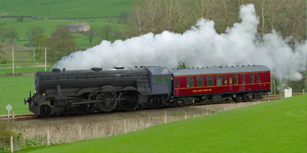
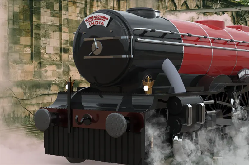
RENDERED IMAGE
CONCLUSIONS
- The replacement of the valve gear system with the real one helps in advancement of the locomotive design.
- The illustration of my project can be used to understand the design methodology like solid modelling, surface modelling and photo-realistic rendering.
- Since it was the first project on modelling a steam locomotive as of my knowledge it can be used as a resource for future reference.
Thus the project was completed by designing and modeling a fully functional Valve Gear System by replacing the Waslschaerts Valve Gear with the Southern Valve Gear.
REFERENCES
- Mechanical Engineering – Brittanica.com
- Chapter 5: Planar Linkage – www.cs.cmu.edu
- The Walschaerts Valve Gear – from Wikipedia
- The Traveling Engineers’ Association: from Project Gutenberg
- Stress Analysis of Bogie Frame Structure – 2017(https://www.diva-portal.org/smash/get/diva2:1194122/FULLTEXT03.pdf)
- History of the Railway Locomotive Head Lamp – presentationmagazine.com
- Classic Projects: LNER Class A3 4472 Flying Scotsman - By Nick Smith Published Monday, May 18, 2015
- Design and Assembly of American Chopper Bike with photo realistic Rendering using SOLIDWORKS – Alex A, November 2020