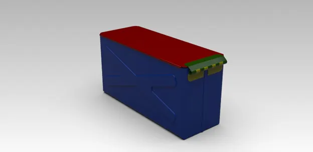
Advanced Sheet Metal designing of a Box Assembly
SHEET METAL DESIGNING OF A BOX ASSEMBLY
OBJECTIVE
The objective of the project is to design a Box Assembly using sheet metal application in Siemens NX software.
INTRODUCTION
Sheet metal is a metal formed by an industrial process into thin, flat pieces. Sheet metal is one of the fundamental forms used in metalworking, and it can be cut and bent into a variety of shapes. Countless everyday objects are fabricated from sheet metal.
A sheet metal Box Assembly was selected for this project to understand the basics of Sheet metal application in Siemens NX. The box assembly has some important features like flange, dimple, normal cutouts etc. The box assembly is a basic component which can be used as a CPU cover and other electronic components etc.
NX, formerly known as "unigraphics", is an advanced high-end CAD/CAM/CAE, which has been owned since 2007 by Siemens PLM Software. In 2000, Unigraphics purchased SDRC I-DEAS and began an effort to integrate aspects of both software packages into a single product which became Unigraphics NX or NX.
DESIGN METHODOLOGY
DESCRIPTION
SHEET PARAMETER = 200MM X 150MM X 1MM (Thickness)
FEATURES USED FOR CREATING BOX ASSEMBLY
- TAB – Creates a base feature by extruding a sketch along a vector by a thickness value or adds material to a planar face. Additional planar sections can be added to generate bends as part of the base feature.
- NORMAL CUT OUT – Cuts material by projecting a sketch onto the model and then cutting perpendicular to the faces intersected by the projection.
- BEND – Modifies the model by bending material on one side of one side of a sketch line, adding a bend between the two sides.
- FLANGE – Adds a flat flange at an angle to a planar face and adds a bend between the two.
- HEM FLANGE – Modifies the model by folding the edge of a sheet metal flange over onto itself for the purpose of safe handling or to increase edge stiffness.
- BREAK CORNER – Rounds or Chamfer a sharp corner of a Tab or Flange.
- UNBEND – Flattens a bend and the material adjacent to the bend.
- MIRROR – Copies a feature or body and mirrors it across a selected plane.
- HOLE – Adds a hole to one or more solid bodies in a part or assembly with options for counterbored, countersunk and threaded.
- DIMPLE – Lifts an area of the model inside a sketch that simulates a stamping tool.
- BEAD – Lifts a material along the contour of a sketch that simulates a stamping tool.
- REBEND – Restores an unbend feature to its previous bent state, along with any features added after the unbend feature.
- UNITE – Combine the volume of two or more solid bodies into a single body.
- FLAT PATTERN – Creates a flat pattern from the formed sheet metal part.
PROCEDURE FOR DESIGNING THE BOX ASSEMBLY
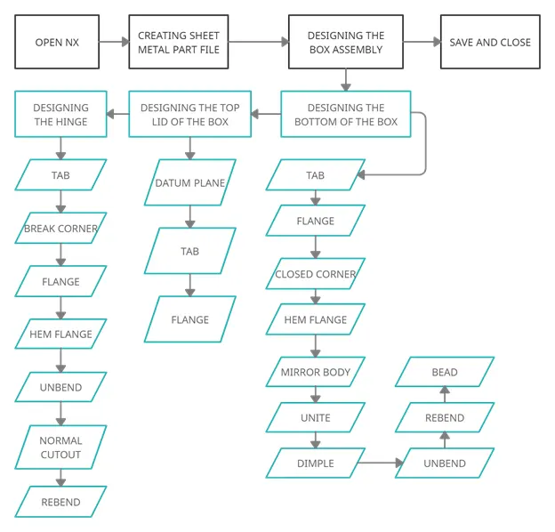
- First the bottom of the box was designed and then the top lid and the hinge of the box were designed.
- The tab was created by drawing the required sketch and then the flange were applied on both sides.
- Then by using the flange and hem flange the side portions were created.
- Then the closed corners were created to close the edge of the sheet metal box.
- Now the first half of the bottom sheet metal box was completed.
- The other half was created using mirror feature and then both the halves were combined using unite feature.
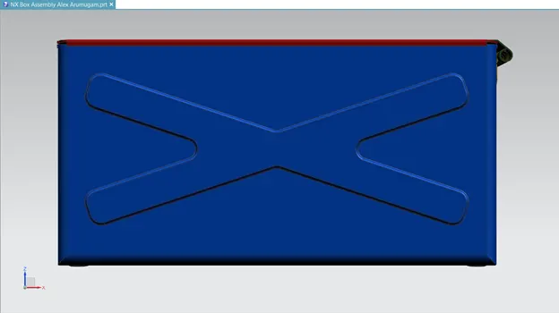
- Then for the side portion x-shaped dimple were created on both sides using dimple and mirror feature.
- For bottom a rectangular dimple was created and the four corners were provided with beads.
- Finally the bottom of the box assembly was completed by creating the hem flange on top edge of the box.
- For creating the top lid a datum plane was created at the required position and a tab was created along with the required flange.
- For creating the hinge for the top and bottom of the box assembly a small rectangular tabs were created on both faces of the box.
- By changing the sweep angle and the open loop hem flange was created.
- Then the flange were unbent using unbend command and the necessary cut outs were provided on both the tabs.
- After creating the cut outs the re-bent operation was carried out using re-bend feature.
- Finally the part was saved by adding appropriate appearances.
STANDARD VIEWS OF THE BOX ASSEMBLY
1.FRONT VIEW
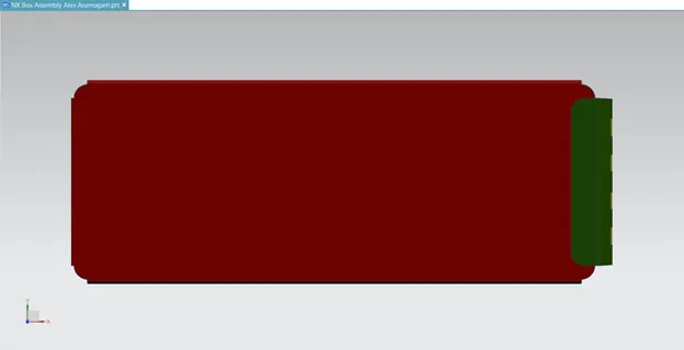
2.TOP VIEW
3.BOTTOM VIEW
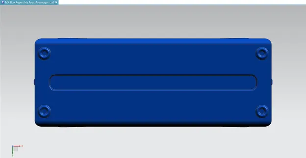
4.RIGHT SIDE VIEW
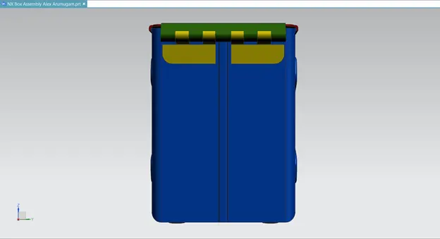
5.ISOMETRIC VIEW
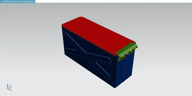
6.DRAWING SHEET BOX ASSEMBLY
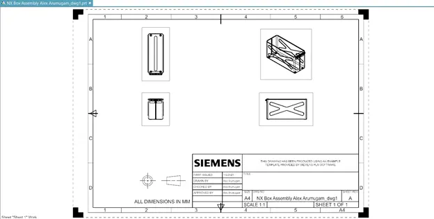
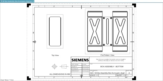
7.DRAWING SHEET OF BOX - BOTTOM
CONCLUSION
Thus the project has been completed by designing a sheet metal box assembly using the sheet metal application in Siemens NX.