Designing a Sheet Metal Casing in NX
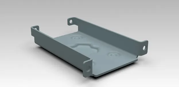
Designing a sheet metal Casing
OBJECTIVE
The objective of the project is to design a sheet metal Casing using Siemens NX-Sheet metal application. The Drawing Sheet should be created for the designed sheet metal casing.
INTRODUCTION
Sheet metal is metal formed by an industrial process into thin, flat pieces. Sheet metal is one of the fundamental forms used in metalworking, and it can be cut and bent into a variety of shapes. Countless everyday objects are fabricated from sheet metal.
Casing is a part which can be an outer shell for various components or products which has various flanges, dimples, cut outs etc.
NX, formerly known as "unigraphics", is an advanced high-end CAD/CAM/CAE, which has been owned since 2007 by Siemens PLM Software. In 2000, Unigraphics purchased SDRC I-DEAS and began an effort to integrate aspects of both software packages into a single product which became Unigraphics NX or NX.
DESIGN APPROACH
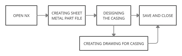
DESIGN METHODOLOGY
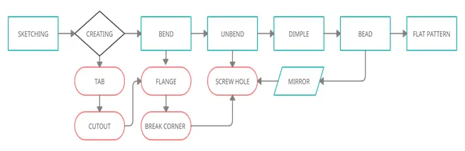
DESCRIPTION
Design requirements:
- SHEET SIZE = 60mm X 50mm X 1mm (Thickness)
- Flange length = 5mm
- Bend Angle = 90 degree
- Dimple Depth = 1 mm
- Screw Clearance hole = Normal H13, M2
- Break Corner = 1mm
- Bead Depth and Radius = 1mm
1. Feature used for creating the Casing:
- TAB – Creates a base feature by extruding a sketch along a vector by a thickness value or adds material to a planar face. Additional planar sections can be added to generate bends as part of the base feature.
- NORMAL CUT OUT – Cuts material by projecting a sketch onto the model and then cutting perpendicular to the faces intersected by the projection.
- BEND – Modifies the model by bending material on one side of one side of a sketch line, adding a bend between the two sides.
- FLANGE – Adds a flat flange at an angle to a planar face and adds a bend between the two.
- BREAK CORNER – Rounds or Chamfer a sharp corner of a Tab or Flange.
- UNBEND – Flattens a bend and the material adjacent to the bend.
- MIRROR – Copies a feature or body and mirrors it across a selected plane.
- HOLE – Adds a hole to one or more solid bodies in a part or assembly with options for counterbored, countersunk and threaded.
- DIMPLE – Lifts an area of the model inside a sketch that simulates a stamping tool.
- BEAD – Lifts a material along the contour of a sketch that simulates a stamping tool.
- REBEND – Restores an unbend feature to its previous bent state, along with any features added after the unbend feature.
- FLAT PATTERN – Creates a flat pattern from the formed sheet metal part.
2. Procedure for designing the Casing
- Created a sheet metal model and saved it as Casing.prt
- Sketched a rectangle using the XY plane and a Tab was created to get a rectangular metal sheet.
- Then a new sketch was drawn on XY plane to create a rectangular cut out using the Normal cut out feature.
- By drawing two parallel lines the sheet was bent on both sides.
- Then the required flange was created by selecting the required edges to create flange.
- Then the sharp corners were filleted using Break Corners.
- Then the bent faces were unbent by keeping the larger face as stationary face.
- Then by sketching four points on the flanges the screw clearance hole were created for the following specification,
Hole direction - Normal to Face
Form - Simple
Screw Type - General Screw Clearance
Screw Size - M2
Fit – Normal (H13)
Depth Limit - Through Body
- Then a dimple was created on the center portion of the casing by using Studio Spline by Selecting the Poles of the Sketch drawn already.
- Then four beads were created on the four corners of the sheet by selecting the circles drawn already and some of the features were mirrored as requirements.
- Finally the bent portions were re-bent using Rebend option.
3. Feature used for Drafting
- NEW SHEET – Creates a new drawing sheet.
- BASE VIEW – Creates a model based view on the drawing sheet.
4. Procedure for Drafting
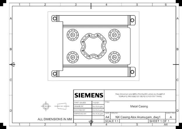
- A new drafting file was created by selecting the A4 size sheet and added the base view by giving proper scale.
- The Flat Pattern View was created and imported in the blank sheet.
- Rotated the model as required.
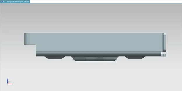
STANDARD VIEWS OF MODELLING
FRONT VIEW
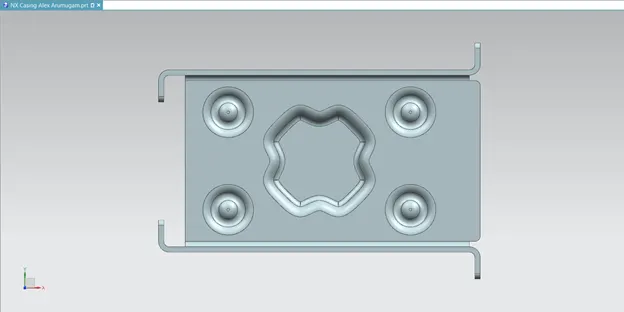
TOP VIEW
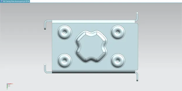
BOTTOM VIEW
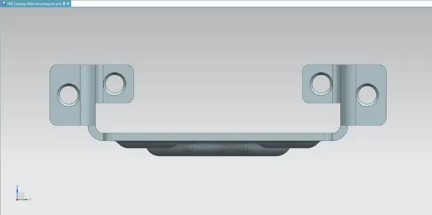
RIGHT SIDE VIEW
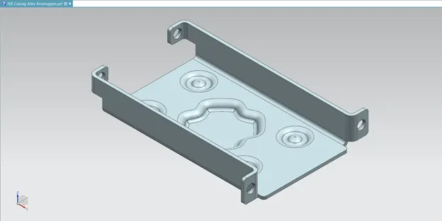
ISOMETRIC VIEW
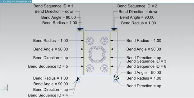
FLAT PATTERN VIEW OF THE CASING
DRAWING SHEET OF CASING
CONCLUSION
Thus the project has been completed by designing and drafting the casing using sheet metal and drawing application in Siemens NX.