Advanced Sheet Metal Design Using NX Cad Challenge_6_Bracket
DESIGN and MODELLING of SHEET METAL BRACKET
Objective:-
- To design and model the sheet metal bracket from a 2D Sketch in sheet metal workbench of NX CAD
- To master the user interface and basic features of Sheetmetal application in NX. like 'Contour flange', 'Normal Cutout', 'Break corner, 'Unbend', 'Bead', 'Rebend' and, 'Hole'.
INTRODUCTION:
Sheet Metal is a metal formed by an industrial process into thin, flat pieces. It is one of the fundamental forms used in metal working and it can be bent into variety of shapes. Countless everyday objects are fabricated from sheet metal. The thickness can vary significantly, extremely thin sheets are called foils and sheets having thickness greater than 6mm are called plates.
Design Methodology:
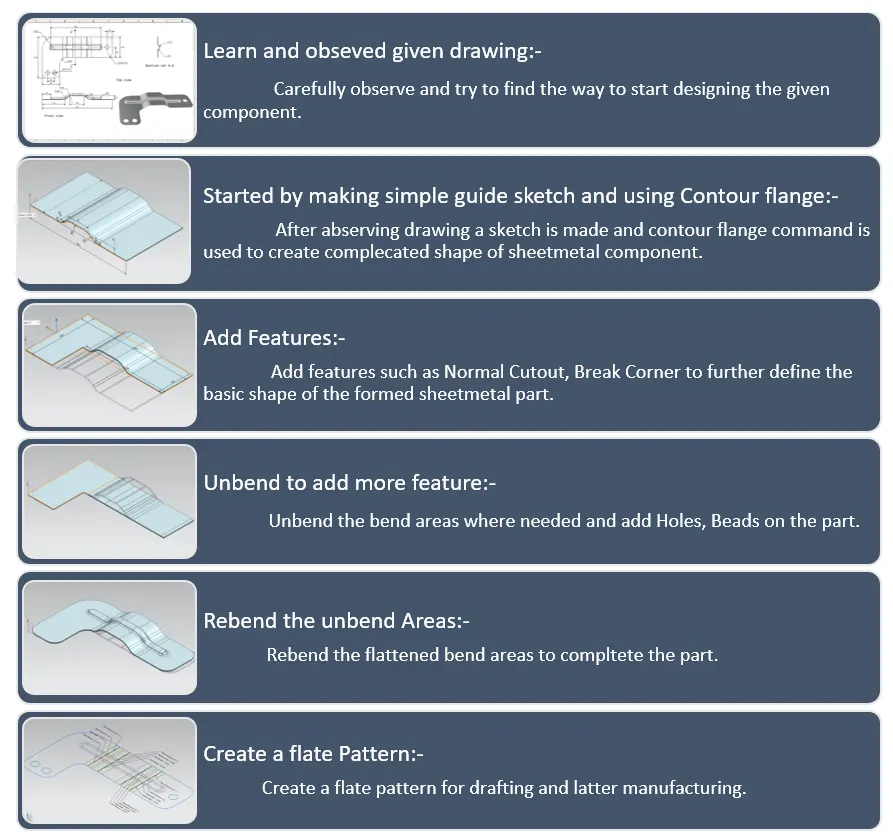
DESCRIPTION:
The tools and features used in the design and modelling of the enclosure are:
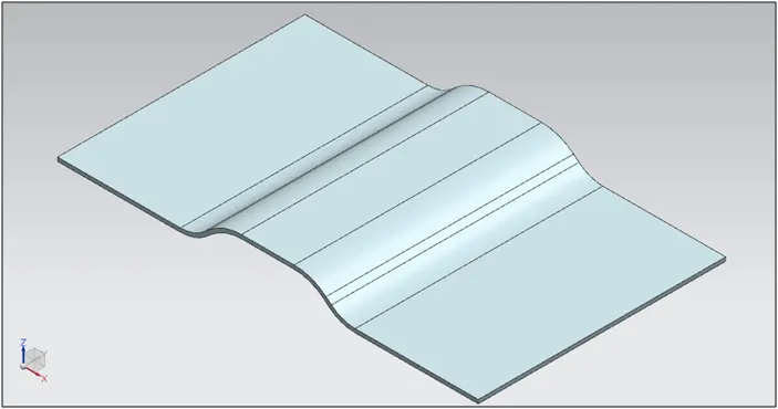
Contour Flange:
A profile for the contour flange is created. Using the command contour flange the 2D Sketch can be converted into a 3D flange.
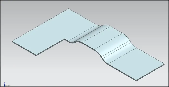
Normal Cut Out: Normal Cutout command extract volumes from sheet metal by using sheet metal production principles. Cutting faces will be perpendicular to the sheet metal surface.
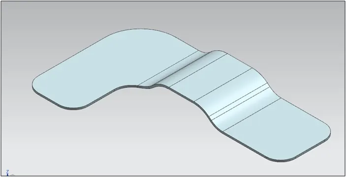
Break Corners:
It is to give smooth finish to the sharp corners.
Unbend:
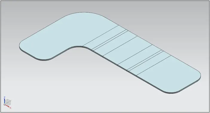
The part is unbend to create additional features such as hole, dimple, beads which otherwise cannot be created if it not unbend. Moreover it also helps to check whether the part is a sheet metal or not. If the part is unbending then it is a sheet metal otherwise it is still a solid body or dumb body.
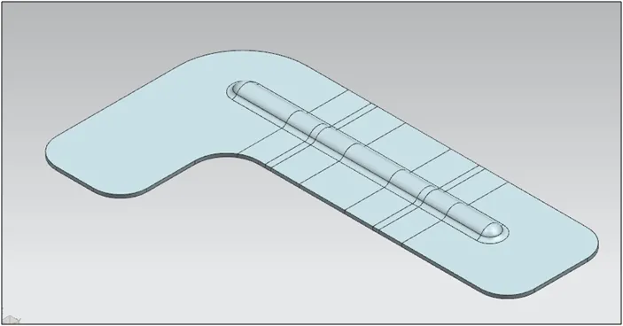
Bead – The bead is like a raised rib in the sheet metal panel. It requires that you have at least one sheet metal panel in the active part as well as an open or closed-loop sketch.
The Bead is another feature that has only a button for Options on the CommandBar.
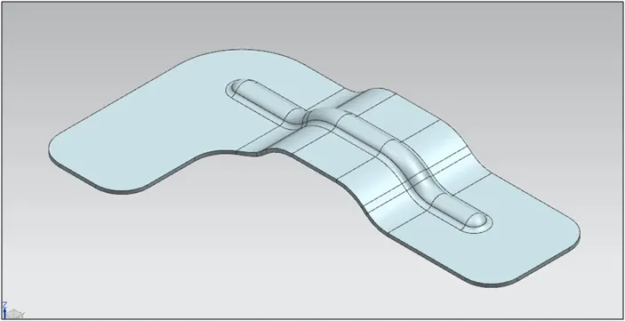
Rebend:
After creation of additional features the part is rebend back to get our required product.
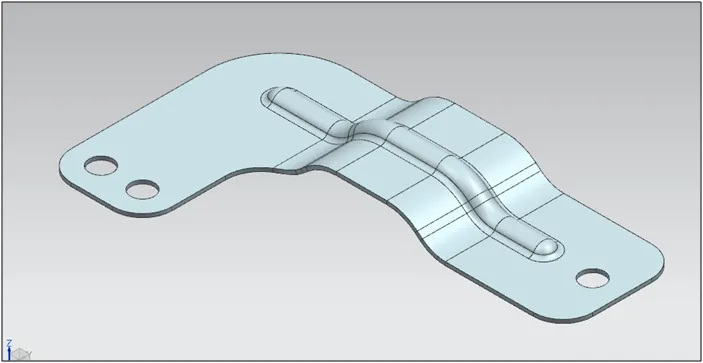
Holes:
The additional features holes are also created. Hole command is available in the sheet metal workbench of the NX CAD. The points where the holes are required are specified.
Flat Pattern View :
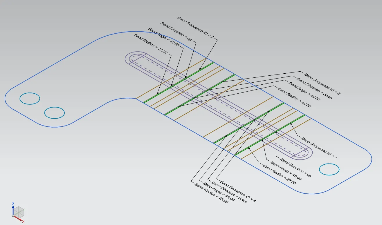
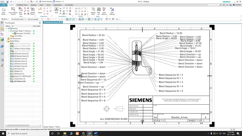
It is the last step of the sheet metal design. The created model is flattened out to know the exact length of the blank required for its manufacturability. By selecting the flat pattern the view of flat pattern is created and this view is added in the drawing sheet.
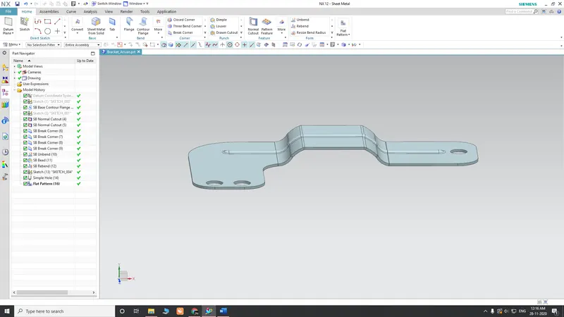
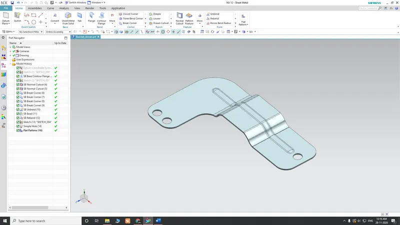
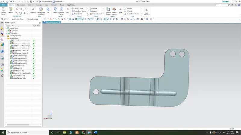
Some Views to Refer feature Tree:
CONCLUSION:
- This project helped me to understand how to convert a 2d Sketch into a 3D sketch.
- Got a good understanding of features like bead, holes, and flanges.
- The creation of flat pattern vie, bend table and the addition of flat pattern view in drawing sheet.