Advanced Sheet Metal Design Using NX Cad Challenge_6_Bracket

OBJECTIVE:
To create a bracket profile on the sheetmetal using beads and holes on the brackets.
INTRODUCTION:
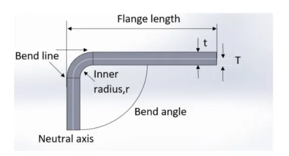
1) Sheetmetal is a metal drawn into thin sheets with some thickness on it basically the thickness range between (0.6-6mm),this may vary to the industrial standards
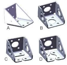
2) Sheet Metal Brackets are the small metallic components which are used in various different industrial utilities for fitting, fixing, holding and fastening.
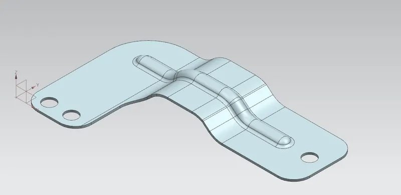
This is an example of brackets.
DESIGN METHODOLOGY:
TOOLS AND FEATURES USED:
1) Countour flange- This tool used to create a extrude of the profile along with the vector.(Menu-Insert-Bend-Contour flange)
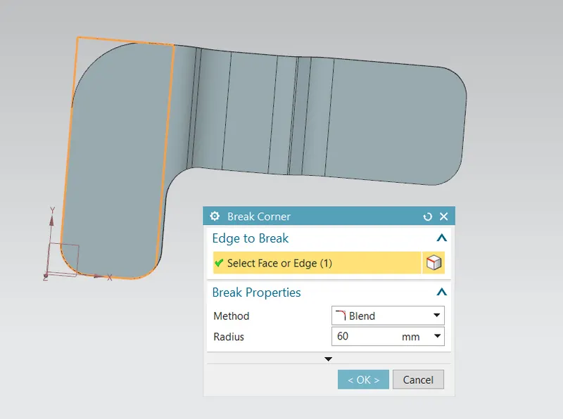
2) Break corner- This tool is used to break the sharp edges on the corners and have smooth curve on the edges.(Menu-Insert-Corner-Break corner)
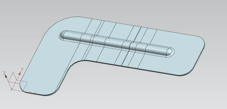
3) Bead- This tool is used to create a punch formation on the sheetmetal and to give strength on the sheetmetal (Menu-Insert-Punch-Bead)
4) Bend/Unbend- This tool is used to create a bend an unbend of sheetmetal. (Menu-Insert-Form-bend/unbend)
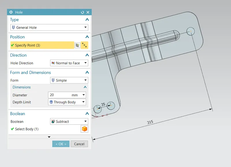
5) Hole- To create a hole on the sheets with respect to length and diameter. (Menu-Insert-Design feature-Hole)
DESIGN APPROACH:
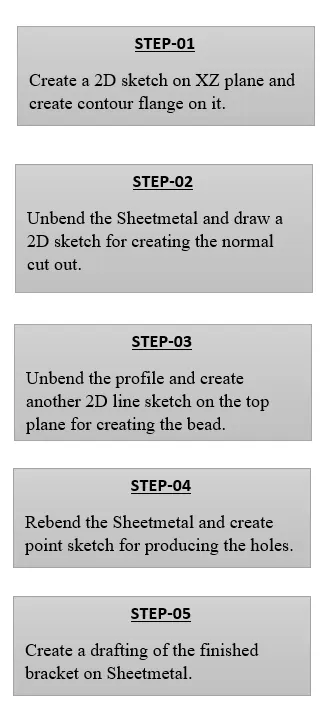
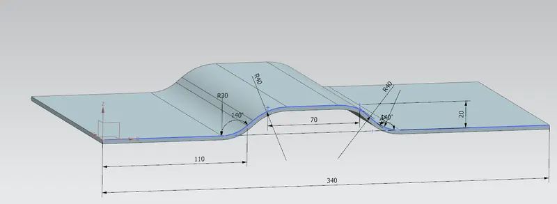
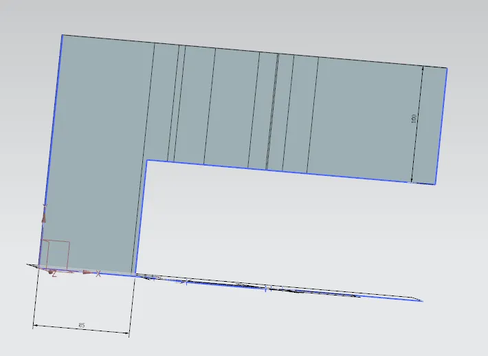
STEP-01: CREATE A 2D SKETCH AND USE A CONTOUR FLANGE TO EXTRUDE IT.
STEP-02: CREATE A NORMAL CUTOUT OF ANOTHER SKETCH.
STEP-03: CREATE A BREAK CORNER ON THE EDGES TO AVOID SHARP EDGES.
STEP-04: CREATE A 2D LINE SKETCH FOR CREATING A BEAD.
STEP-05:CREATE A POINT SKETCH TO CREATE A HOLE.
VIEWS:
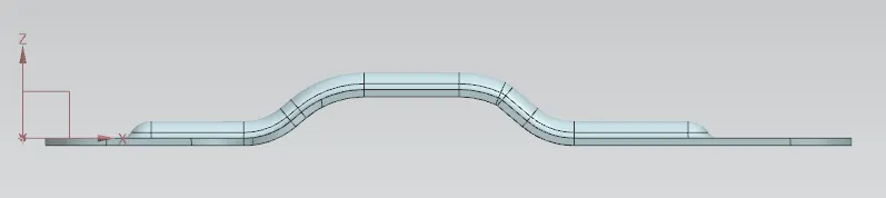
1) Front view:
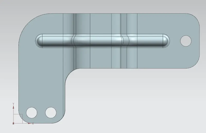
2) Top view:
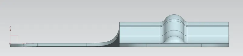
3) Side view:
4) Isometric view:
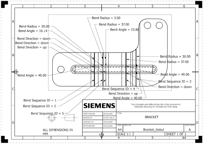
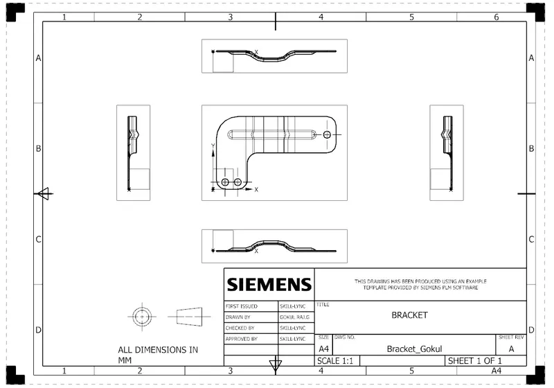
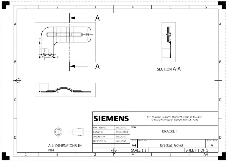
DRAFTING:
CONCLUSION:
FINALLY THE BRACKET IS DONE ON THE SHEETMETAL BY SIEMENS NX 11 AND LEARNED ABOUT THE FEATURES USED ON THE BRACKETS.