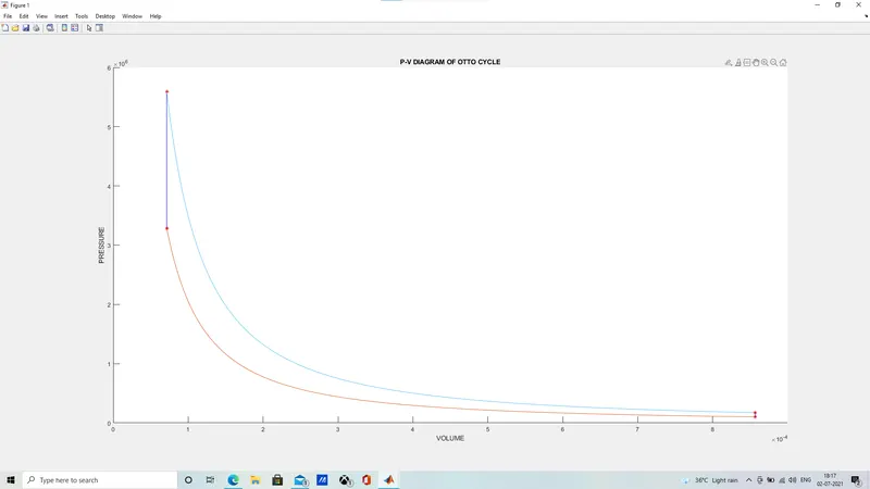
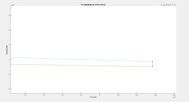
P-V DIAGRAM PLOT OF OTTO CYCLE USING MATLAB
The typical air-standard Otto-cycle which is generally used in the Petrol engines has 4 different process in its cycle. They are as follows
PROCESS 1-2 : ADIABATIC COMPRESSION
PROCESS 2-3 : CONSTANT VOLUME HEAT ADDITION
PROCESS 3-4 : ADIABATIC EXPANSION
PROCESS 4-1 : CONSTANT VOLUME HEAT REJECTION
STEPS FOLLOWED WITH CODE AND EXPLANATION
STEP 1 : PROVIDING THE REQUIRED INPUTS REQUIRED
clear all
close all
clc

%inputs
gamma = 1.4;
T3 = 2300;

%state variables
p1 = 101325;
T1 = 500;

%value of cv at 1200K based on avg temperature of the cycle
c_v = 0.886;
c_p = 1.173;
k = c_p/c_v;

%engine geometric parameters
bore = 0.1;
stroke = 0.1;
con_rod = 0.15;
cr = 12;
STEP 2: CALCULATING THE SWEPT VOLUME AND CLEARANCE VOLUME FROM THE GIVEN ENGINE PARAMETERS
%calculating swept volume and clearance volume
v_swept = (pi/4)*bore^2*stroke;
v_clearance = v_swept/(cr-1);

v1 = v_swept + v_clearance;
v2 = v_clearance;
STEP 3: CALCULATING THE STATE VARIABLES AT POINT 2
%state variables at point 2
%p2v2^gamma = p1v1^gamma
p2 = p1*cr^gamma;

%p1v1/t1 = p2v2/t2
T2 = (p2*v2*T1)/(p1*v1);
STEP 4: DEFINING THE ENGINE KINEMATICS FUNCTION THAT RETURNS THE VALUE OF VOLUME FOR COMPRESSION AND EXPANSION PROCESS
function [V] = engine_kinematics(bore, stroke, con_rod, cr, start_crank, end_crank)

a = stroke/2;
R = con_rod/a;

v_swept = (pi/4)*bore^2*stroke;
v_clearance = v_swept/(cr-1);

theta = linspace(start_crank, end_crank, 100);

term1 = 0.5*(cr-1);
term2 = R + 1-cosd(theta);
term3 = (R^2 - sind(theta).^2).^0.5;

V = (1 + term1*(term2 -term3)).*v_clearance;


end
STEP 5: CALCULATING THE VOLUME AND PRESSURE DURING COMPRESSION USING THE EXPRESSION (P1*V1^GAMMA = CONSTANT)[VALUE OF VOLUME DURING COMPRESSION IS CALCULATED BY CALLING THE ENGINE KINEMATICS FUNCTION THROUGH THE ANGLE 180,0]
constant_c = p1*v1^gamma;
V_compression = engine_kinematics(bore,stroke,con_rod,cr,180,0);
P_compression = constant_c./V_compression.^gamma;
STEP 6: CALCULATING THE STATE VARIABLES AT POINT 3
%state variables at point 3
v3 = v2;

%p3v3/t3 = p2v2/t2
p3 = (p2*T3)/T2;
STEP 7: CALCULATING THE VOLUME AND PRESSURE DURING EXPANSION USING THE EXPRESSION (P3*V3^GAMMA = CONSTANT)[VALUE OF VOLUME DURING EXPANSION IS CALCULATED FROM THE ENGINE KINEMATICS FUNCTION THROUGH THE ANGLE 0,180]
constant_c = p3*v3^gamma;
V_expansion = engine_kinematics(bore,stroke,con_rod,cr,0,180);
P_expansion = constant_c./V_expansion.^gamma;
STEP 8: CALCULATING THE STATE VARIABLES AT POINT 4
%state variables at point 4
v4 = v1;

%p3v3^gamma = p4v4^gamma
p4 = p3*(v3/v4)^gamma;

%finding T4
T4 = (p4*v4*T3)/(p3*v3);
STEP 9: PLOTTING
figure(1)
hold on
plot(v1,p1,'*','color','r')
plot(V_compression, P_compression)
plot(v2,p2,'*','color','r')
plot(v3,p3,'*','color','r')
plot([v2 v3],[p2 p3],'color','b')
plot(V_expansion, P_expansion)
plot(v4,p4,'*','color','r')
plot([v4 v1],[p4 p1],'color','b')

%plot([v2 v3],[p2 p3],'color','b')
%plot([v1 v4],[p1 p4],'color','b')

title('P-V DIAGRAM OF OTTO CYCLE')
xlabel('VOLUME')
ylabel('PRESSURE')
STEP 10: CALCULATING THE THERMAL EFFICIENCY
%CALCULATING THE THERMAL EFFICIENCY

q_in_to_q_out = (T4-T1)/(T3-T2);
Thermal_Efficiency_otto = 1 - q_in_to_q_out;
STEP 11: CALCULATING CARNOT EFFICIENCY
%CALCULATING THE CARNOT EFFICIENCY
carnot_efficiency = 1-(T1/T3);
ERRORS FACED:
1. ERROR IN THE GRAPH PLOTTED DUE TO MISPLACED PARANTHESIS IN THE CODE IN LINE 33
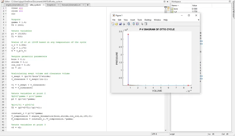
REMOVED THE PARANTHESIS IN THE LINE 33 TO GET THE DESIRED PLOT
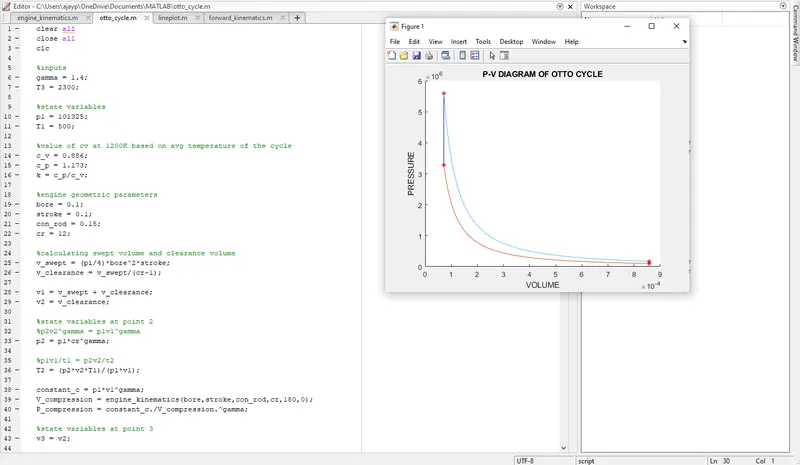
FINAL OUTPUTS:
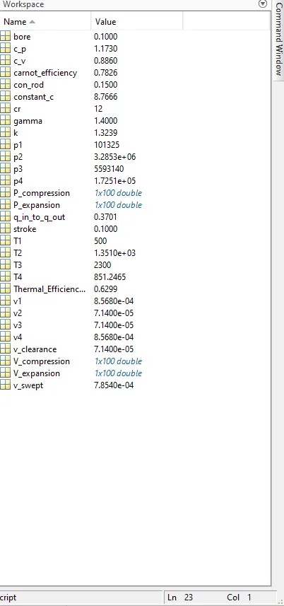
HERE IT CAN BE NOTED THAT THE EFFICIENCY OF THE OTTO CYCLE IS LESSER THAN THE CARNOT EFFICIENCY