Week - 4
CHALLENGE 1:
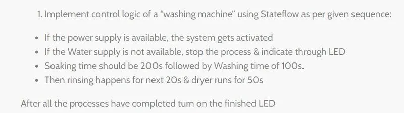
SIMULINK MODEL FOR IMPLEMENTING THE CONTOL LOGIC OF A WASHING MACHINE USING STATEFLOW AS PER THE GIVEN SEQUENCE:
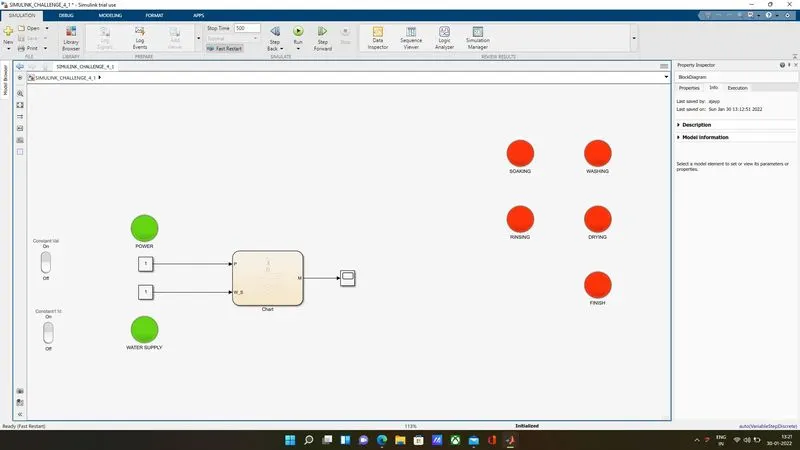
WORKING:
1. The following blocks are used in the shown model:
- ROCKER SWITCH (2) - to toggle ON/OFF the POWER & WATER SUPPLIES.
- CONSTANT BLOCKS (2) - to connect the ON/OFF values to the Input of the chart block.
- SCOPE BLOCK - to view the Output from the chart block.
- LAMPS (7) - to view the results as LED.
- CHART - to provide the control logic.
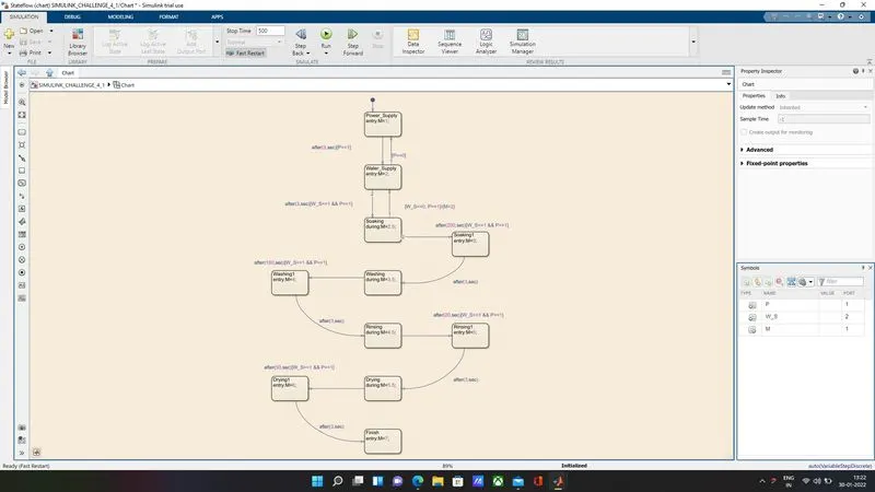
2. The control logic is given in the chart block as shown below.
3. The variables in the chart used for Inputs are P indicating the Power supply while W_S indicates the Water Supply, for Output M is used.
4. Once the Power and Water are turned ON after a gap of 3 seconds Soaking starts and continues for a period of 200 seconds.
5. Then a delay of 3 seconds is given after which the Washing process starts and continues for a period of 100 seconds.
6. Again after a delay of 3 seconds once the Washing process is completed, Rinsing starts and continues for the next 20 seconds.
7. This is followed by a 3 second delay and then Drying process starts and finishes at the end of the next 50 seconds.
8. Finally the Finish LED turns on after Drying is completed followed by a 3 second delay.
SIMULINK CHART SHOWING THE CONTROL LOGIC USED:
OUTPUTS AT DIFFERENT STAGES OF THE FUNCTIONING OF THE MACHINE AS PER THE GIVEN CONDITIONS:
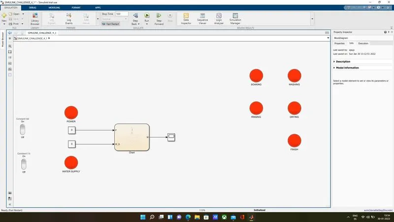
SIMULINK MODEL WINDOW WHEN POWER AND WATER SUPPLY IS TURNED OFF:
SIMULINK MODEL WHEN BOTH POWER AND WATER SUPPLY ARE TURNED ON:
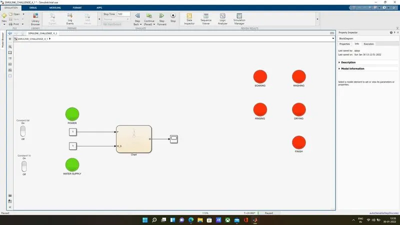
SIMULLINK MODEL AFTER 30 SECONDS - SOAKING ON:
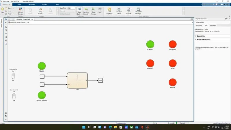
SIMULINK MODEL AFTER 240 SECONDS - WASHING ON:
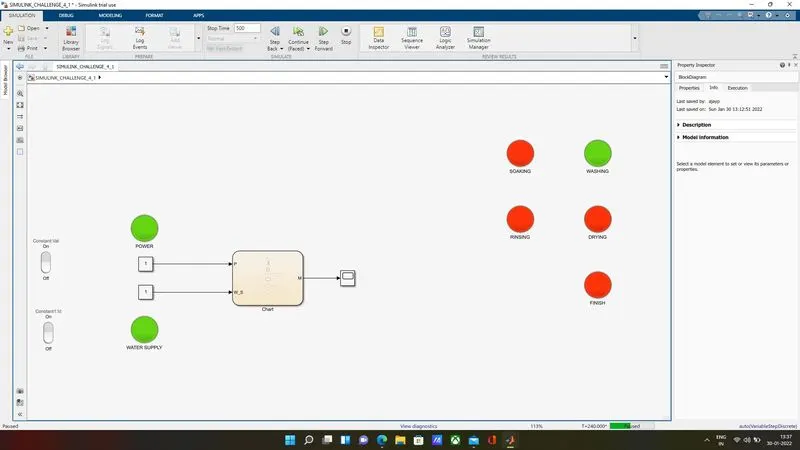
SIMULINK MODEL AFTER 350 SECONDS - RINSING ON:
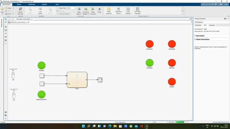
SIMULINK MODEL AFTER 380 SECONDS - DRYING ON:
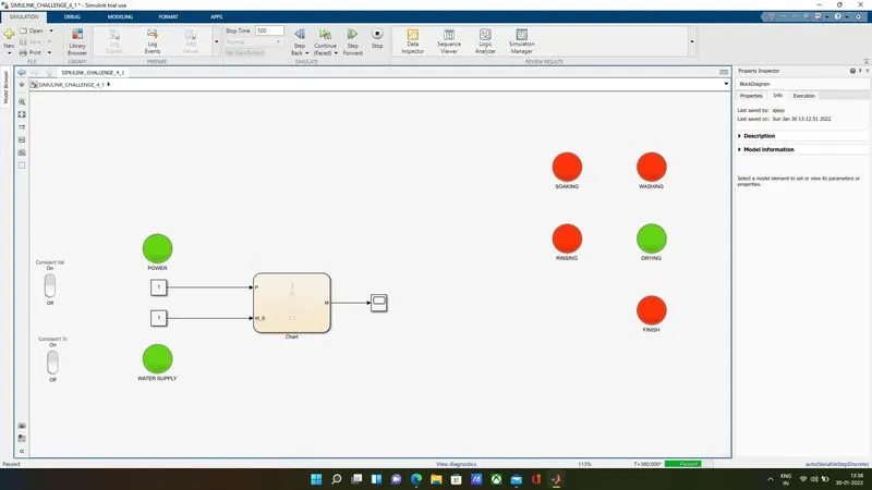
SIMULINK MODEL AFTER THE END OF THE CYCLE - FINISH ON:
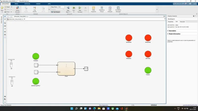
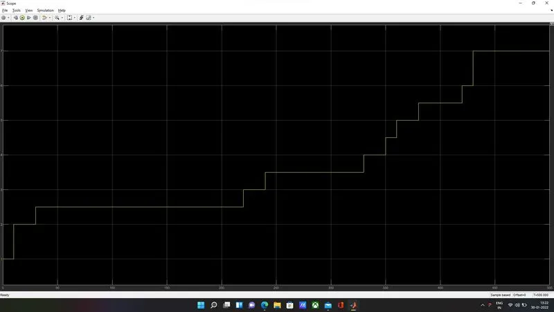
SIMULINK SCOPE WINDOW:
The Scope block output window shows the plot between time and the output M (values 1 through 7).
The values of M for each stages are as follows:
- M = 1 - Power ON
- M = 2 - Water ON
- M = 2.5 to 3 - Soaking ON
- M = 3.5 to 4 - Washing ON
- M = 4.5 to 5 - Rinsing ON
- M = 5.5 to 6 - Drying ON
- M = 7 - Finish
CHALLENGE 2:
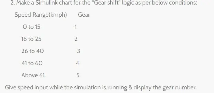
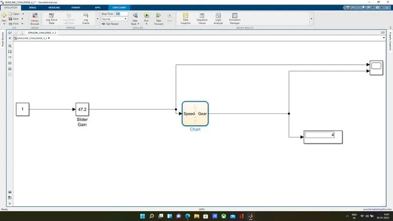
SIMULINK MODEL FOR GEAR SHIFT LOGIC USING SLIDER GAIN TO GIVE SPEED INPUT WHEN SIMULATION RUNS:
SIMULINK CHART WINDOW SHOWING THE CONTROL LOGIC USED:
WORKING:
1.The following are the blocks used in the model:
- SLIDER GAIN - to provide the input when the simulation is running.
- CONSTANT BLOCK - to give the initial input connection to slider gain block.
- CHART - to give the control logic for the model.
- DISPLAY - to display the current value of gear when the simulation is running.
- SCOPE - to view the plot between the speed and the gear shift after the simulation is completed.
2. The Input variable is Speed and the Output is Gear.
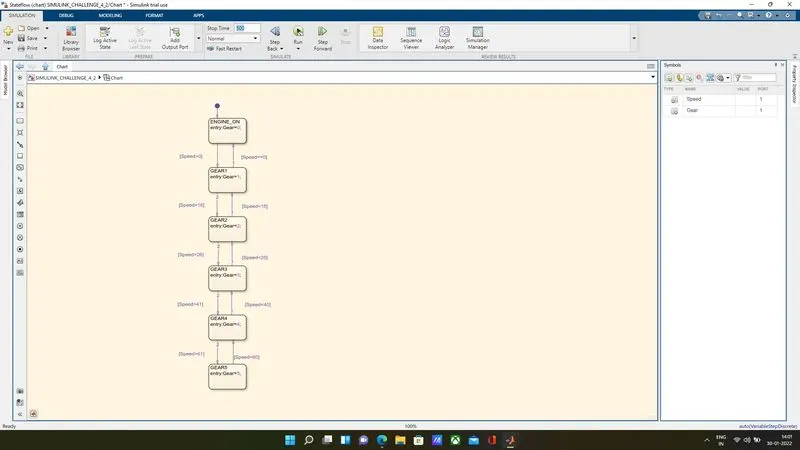
3. In the chart window, control logic is defined as follows:
- ENGINE ON State - Gear is set to 0.
- GEAR1 State - Gear is set to 1; condition is set to be Speed > 0 and control flows back to Neutral/Engine ON state when the value of Speed == 0.
- GEAR2 State - Gear is set to 2; condition is set to be Speed > 16 and control flows back to GEAR1 state when the value of Speed < 15.
- GEAR3 State - Gear is set to 3; condition is set to be Speed > 21 and control flows back to GEAR2 state when the value of Speed < 25.
- GEAR4 State - Gear is set to 4; condition is set to be Speed > 41 and control flows back to GEAR3 state when the value of Speed < 40.
- GEAR5 State - Gear is set to 5; condition is set to be Speed > 61 and control flows back to GEAR4 state when the value of Speed < 60.
4. The Scope block is then used to view the plot between the Speed and the Gear shifted for the given speed.
SIMULINK SCOPE WINDOW AS PER THE INPUTS GIVEN USING SLIDER GAIN:
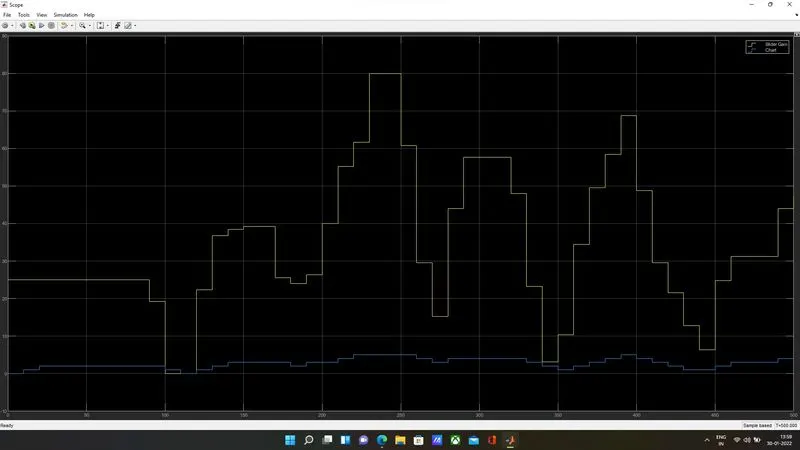
The input is varied during the runtime of the simulation for the given timespan of 500 seconds and the corresponding shift in gears is viewed from the Scope block used in the model.
CONCLUSION:
Thus using the SIMULINK model & the CONTROL LOGIC the required outputs are achieved for simulating the Working of a WASHING MACHINE & GEAR SHIFT.