Week -2
SIMULINK MODELING:
1. MAKING A SIMULINK MODEL OF A DOORBELL USING A SOLENOID BLOCK WITH 2 SECOND RELEASE OF SWITCH:
SIMULINK MODEL:
WORKING:
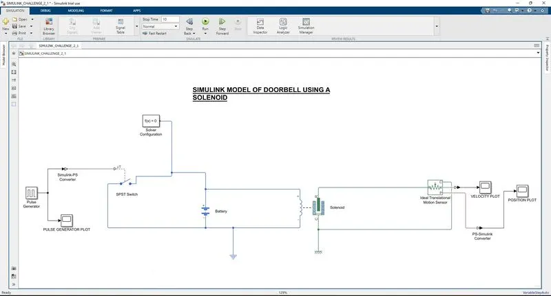
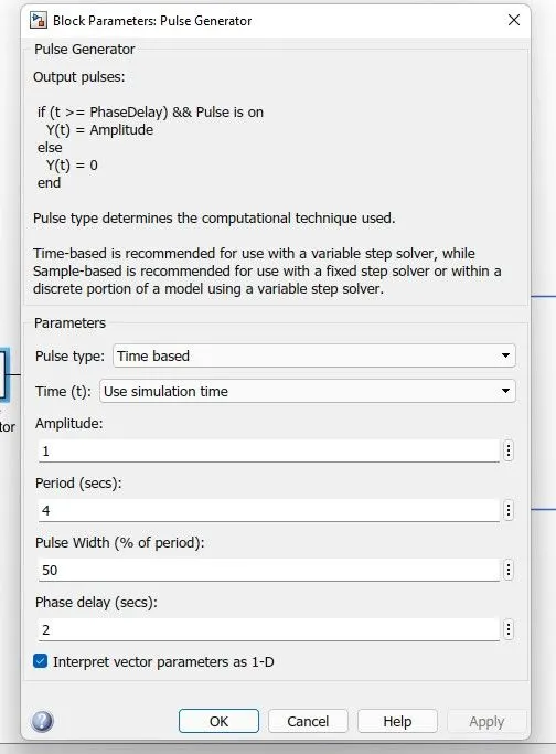
1. Pulse Generator block is used to generate the pulse to make the switch to Switch to ON state. Pulse Generator properties are set as shown below:
2. SIMULINK-PS Converter is used to convert the Simulink system signal into a Physical signal.
3. A SPST Switch is used to control the Power.
4. Power Source is required for the system, hence a battery is connected as shown.
5. Now the Solenoid is connected with the battery and the switch and an electrical reference block is also connected to ground the system.
6. Then the Solenoid block is connected with Ideal Translational Motion Sensor in order to note the motion caused by the solenoid.
7. The Ideal Translational Sensor is then connected to the respective scope blocks to get the position and velocity plots.
8. Also the system containing all the Mechanical blocks are then connected to the Mechanical Translational Reference.
9. This is followed by providing a Solver Configuration to the system to provide the Solver settings for the simulation to run.
INPUT PLOT:
OUTPUT PLOTS:
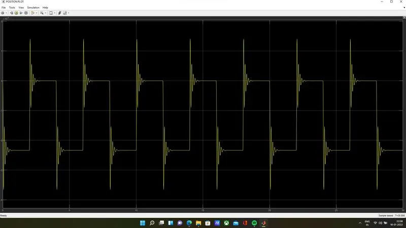
POSITION PLOT:
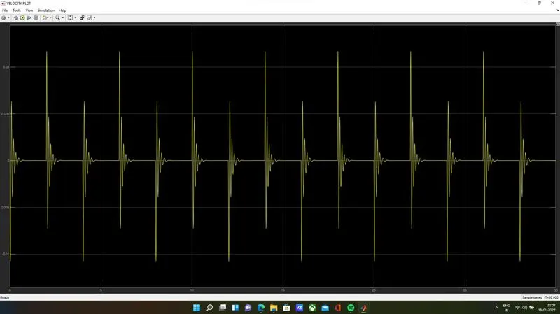
VELOCITY PLOT:
OBSERVATION:
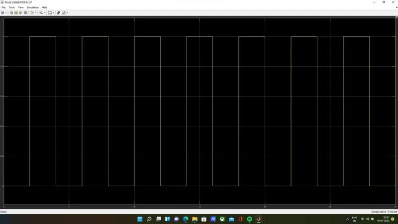
As per the Pulse Generated, whenever the Threshold value of the switch given is crossed the system gets the power and the Solenoid gets magnetized. This in turn causes the Hammer to strike the bell with a holding time of 2seconds as per our input and the same time is also acts as a holding time for the system to repeat the action.
2. USING A THERMISTOR TO SENSE THE TEMPERATURE OF A HEATER & TURN ON OR OFF THE FAN AS PER THE GIVEN CONDITIONS:

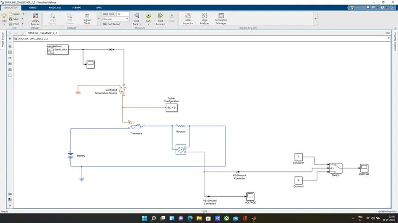
SIMULINK MODEL:
WORKING:
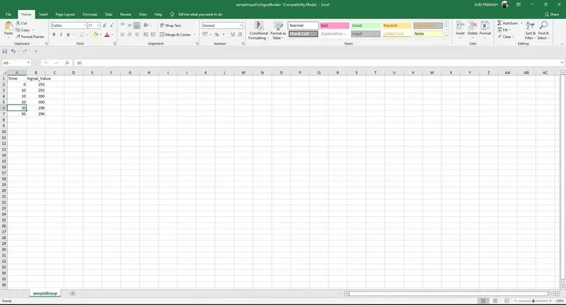
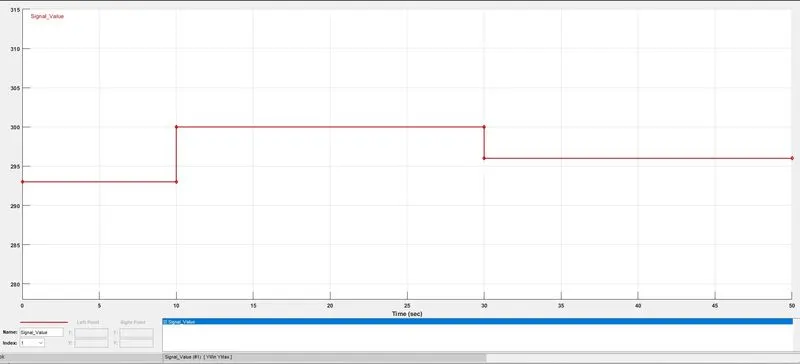
1. Signal Builder block is used to give the inputs as required. Through the import from file option the values are given.
2. The Simulink signal is then converted into a Physical Signal using a Simulink-PS Converter.
3. The physical signal is fed into the Controlled Temperature Source block in which A port is connected to a Thermal Reference.
4. The B port in the Controlled Temperature Source block is connected to a Solver to define the solver settings for the simulation and also is connected to A port of a Thermistor.
5. The positive end of the Thermistor is connected to a Battery source while the negative end is connected to the positive end of aa Resistor.
6. The Resistor is connected with Voltage Sensor as per the block diagram shown & the negative end is connected to the negative end of the Battery.
7. Electrical Reference is given to ground the system.
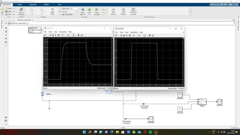
8. The Voltage Sensor signal is then converted to 2 different Simulink signals using 2 PS-Simulink Signal Converters which are connected to a scope for checking the Voltage and to provide the criterion for the Switch respectively.
9. As per the Voltage Plot the Threshold value is chosen to be 0.012V in the Switch.
10. 2 constant blocks are used to give the values to the Switch Ports based on the criteria set.
11. A Scope block is used to get the Plot from the Switch Block.
INPUT PLOT:
VOLTAGE PLOT & OUTPUT PLOT: