OTTO CYCLE
Aim
To find the pressure, volume, and temperature of the otto cycle at different states and plot graph P vs v graph.
Introduction:
Otto Cycle:
Otto cycle is used in internal combustion engines. It follows the 4 states that is 1->2 is isentropic compression process, 2->3 is isochoric heat addition process, 3->4 is isentropic expansion process, 4->1 is isochoric heat rejection process.
Forumlas:
1. 
i.`R= "connecting rod length"/"crank pin radius"`
ii.`"Crank pin radius (a)" = "stroke length"/2`
rc is compression ratio
`theta` is crank angle.
2. `Volume swept = pi/4 * d^2. L`
where d is bore diameter in m.
L is the stroke length in m.
3.`"Clearance Volume" = "Volume swept"/(compression ratio-1)`
4.`V1 = swept volume + "clearance volume"`
5. `V2 = "Clearance volume"`
6. 
7. Isentropic Compression Process
`P1V1^gamma = P2V2^gamma`
8. Thermal Efficiency
`eta = 1- Cr^(1-gamma)`
Intial Conditions
bore diameter = 0.1m
stroke length = 0.1m.
compression ratio = 12
connecting rod ratio = 1
P1 = 101325 Pascals.
T1 = 500K
Tmax = T3 = 2300K.
`gamma`= 1.4.
Logic Used:
The pressure, volume, and temperature are calculated sequentially from state 1 to state 4.
The change in volume and pressure during the isentropic compression and expansion process is calculated using the ode function.
The graph is plotted for P vs V for different 4 states.
Code:
close all
clear all
clc

%inputs

%bore represents the bore diameter in m
bore = 0.1;

% stroke represents the stroke length in m
stroke = 0.1;

%compression ratio
cr = 12;

%connecting rod ratio
con_rod = 1;

% swept volume and clearance volumer formula
v_s = pi*0.25*bore^2*stroke;
v_c = v_s/(cr-1);

% volume at state 1
v1 = v_s+v_c;

%volume at state 2
v2= v_c;

%Pressure and temperature at state 1
p1 = 101325;
t1 = 500;

%temperature at state 3
t3 = 2300;

gamma = 1.4;

%Pressure and temperature after isentropoic compression process i.e., at
%state 2
p2 = p1*(cr)^gamma;

t2 = p2*v2*t1/(p1*v1);
c_constant = p1*v1^gamma;

%change in pressure and volume for every 1 degree change of the crank
V_compression = engine_kinematics(bore,stroke,con_rod,cr,180,0); %<-- call for function engine_kinematics
P_compression = c_constant./(V_compression.^gamma);

%Pressure and temperature at constant volume compression process (state 3)
v3 = v2;
p3 = p2*t3/t2;

%Constant c at state 3
c_constant = p3*v3^gamma;

%Pressure and temperature after isentropoic expansion process i.e., at
%state 3
V_expansion = engine_kinematics(bore,stroke,con_rod,cr,0,180); %<-- call for function engine_kinematics
P_expansion = c_constant./(V_expansion.^gamma);

%pressure and volume at state 4.
v4=v1;
p4 = (v3/v4)^gamma*p3;

%thermal efficiency of the engine in percentage

n = (1 - cr^(1-gamma))*100

%Ploting of graph of all 4 states.
figure(1)
hold on
plot (v1,p1,'*','color','r') %<-- point representing state 1
plot (V_compression,P_compression,'color','g') %<-- curve representing isentropoic compression process
plot (v2,p2,'*','color','r') %<-- point representing state 2
line ([v2 v3],[p2 p3],'color','b')  %<-- line representing constant volume heat addition process
plot (v3,p3,'*','color','r') %<-- point representing state 3
plot (V_expansion,P_expansion,'color','g') % <-- curve representing isentropic expansion process
line ([v4 v1],[p4 p1],'color','b') %<-- line representing constant volume heat rejection process
plot (v4,p4,'*','color','r') %<-- point representing state 4
xlabel('V')
ylabel('P')
Function to find the Volume change during isentropic compression and expansion process.
%Function to calculate change in volume in the combustion chamber.
function [V] = engine_kinematics(bore,stroke,con_rod,cr,start_crank,end_crank)

        a = stroke/2;
        R = con_rod/a;

        v_s = pi*bore^2*stroke*0.25;
        v_c = v_s/(cr-1);

        %theta is angle of crank from top dead centre
        theta = linspace(start_crank,end_crank,180);

        %Formula to find the change in volume inside the engine chamber as
        %combustion takes place
        %The forumula is divided into smaller parts to reduce the
        %compelxity while coding.

        term_1 = 0.5* (cr -1);
        term_2 = R+1 - cosd(theta);
        term_3 = (R^2 - sind(theta).^2).^0.5;

        V = (1+ term_1*(term_2 - term_3)).*v_c;
end
Explanation.
The pressure, volume, and temperature are found sequentially from state 1- state 4.
The pressure and temperature for the isentropic compression and expansion process is found out by using
Isentropic Compression Process
`P1V1^gamma = P2V2^gamma`
Isentropic Expansion Process
`P3V3^gamma = P4V4^gamma`
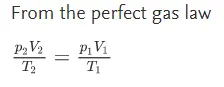
The pressure and temperature for constant volume heat addition and heat rejection are found out using the perfect gas law equation.
Use of function:
The function created is used for the calculation of change in volume during the isentropic compression and expansion process.
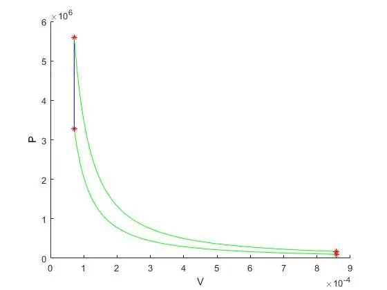
Graph
The graph is plotted between P Vs V.
red dots represent the 4 states in the otto cycle.
The green line represents the isentropic compression and expansion process
Blueline represents the constant volume heat addition and heat rejection process.
P Vs V