Multibody Analysis of Trunk lid mechanism using Altair Motionview
https://drive.google.com/file/d/1A8pyel0ki08KrB1lK7rTL2tDzI6LF9YI/view?usp=sharing
Aim
To design the Trunk lid mechanism using Bistop Function and Curve Function
Software Used
Altair Motionview / Hypergraph / Hyperview
PROCEDURE
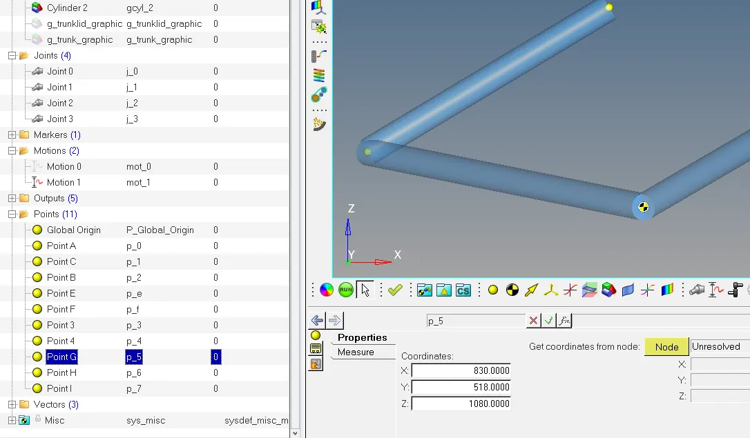
- First plot points as given below :
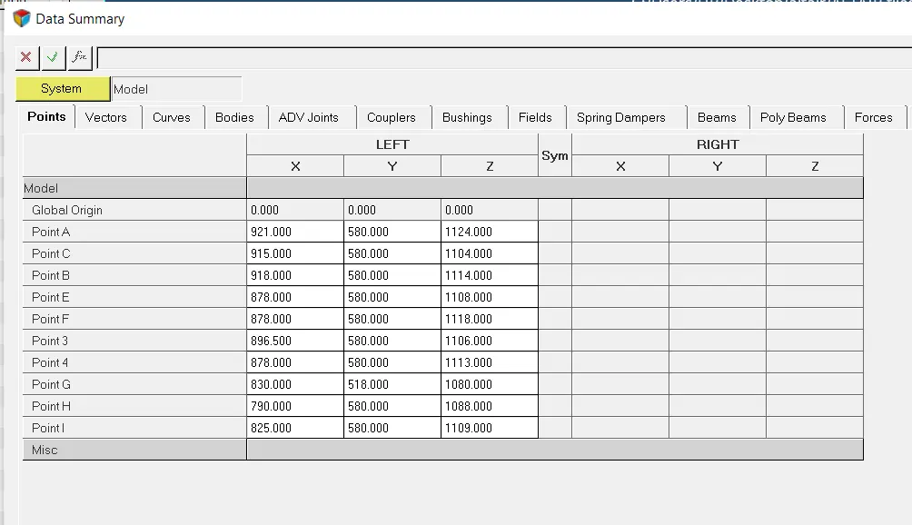
2. Now create bodies for the follower , coupler , input link assign COM using point B , point 3 , point G .
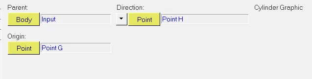
3. Now create associated graphics for each bodies like this
4. You can give some random values of inertia and mass for the bodies such as
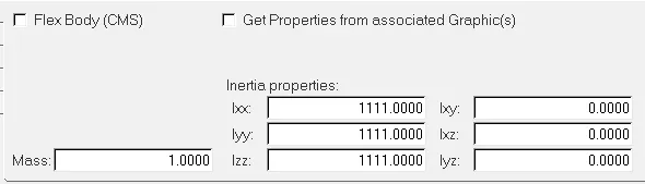
5. Do remember , that after creating the graphics of the four bar with the extended input link , change the COM from point 4 to point G beacause according to the COM critiria the COM is the location where the average mass of all the parts of the system is located . So we can assume Point G to be the new COM after the extension of the input link .
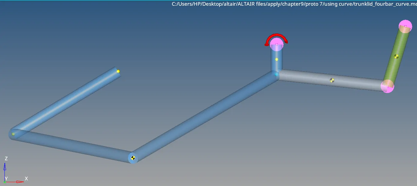
7. Now we have to add joints , 3 revolute joints at point A , point C and point F and 1 inline joint at point C .
6. Now the structure is ready .
Assigning the motion
To use the motion feature , you have to add a motion from the taskbar.
1. MOTION USING CURVE :
- We will first add one curve for to define a motion . For that you have to add one curve then add the curve file from the location where that file is saved .
- Mention the block number and column under the x axis , y axis options so that the curve function can relate the entities like displacement and time with the motion feature .

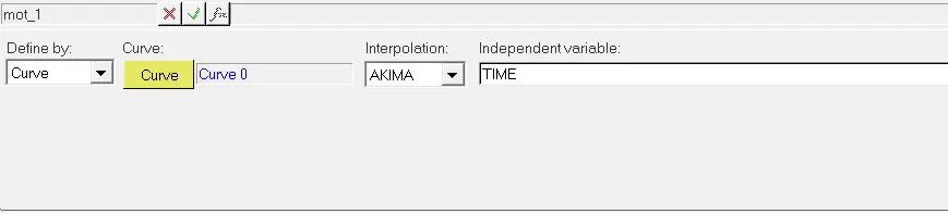
- Now go under the motion feature to activate the curve and use ' AKIMA' interpolation method . We use 'AKIMA' when the data points are equally spaced to get smooth curves .
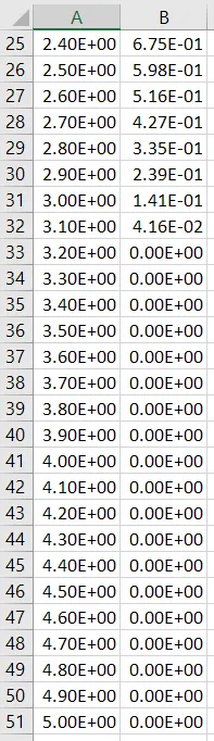
Now as we know we have to modify the motion curve because the trunk lid passes across the BIW Fixture of the car model instead of stopping exactly when it touches the car . So we have to modify the motion curve . We will update all the values of the displacements after time 3.1 seconds to 0 .
2. Using the BISTOP Function
- We can also use BISTOP Function to stop the trunk lid exactly when it comes into contact with the BIW Fixture of the car .
- We know the syntax of the BISTOP Function

where
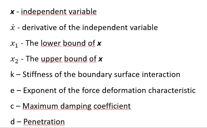
in this we have to remember that the value of X1 is always smaller than X2 .
- To activate BISTOP first , add the Force in the model tree then activate BISTOP by using expression and making BISTOP Expression in the function builder .
- Using HIT and TRIAL method i got the values of X1 and X2 that satisfy the condition which is to stop the trunk lid at the time when it touches the car . That were 35 and 65 .
- The BISTOP Function along with the parameters that i used was :
BISTOP(AZ({j_0.joint_i.idstring},{j_0.joint_j.idstring}),WZ({j_0.joint_i.idstring},{j_0.joint_j.idstring}),35*PI/180,95*PI/180,1e4,2,100,0.1)
IMPORTING CAD GEOMETRY
- From the Tools menu, select Import CAD or FE.
- From the Input File option drop-down menu, select HyperMesh.
- Click the browser button next to Input File and select trunklid.hm, located in <working
directory>, as your input file.</working - Click the file browser button next to Output File and specify the name for the output H3D
files as trunklid.h3d under .
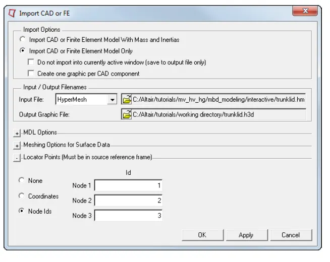
- Click OK to begin the import process.
- Click the Graphics icon on the Reference Entity toolbar.
- Select g_trunklid - from the graphics area. In the Connectivity tab, double click the Body collector under Parent. Select Input
Link from the Select a Body list. - Click OK.
The Graphics panel is displayed. - Similarly, select the newly created g_trunk graphic from the Project Browser and set the
as Ground Body. Click the Save Model icon on the Standard toolbar.
OUTPUT CREATION AND ITS ANALYSES
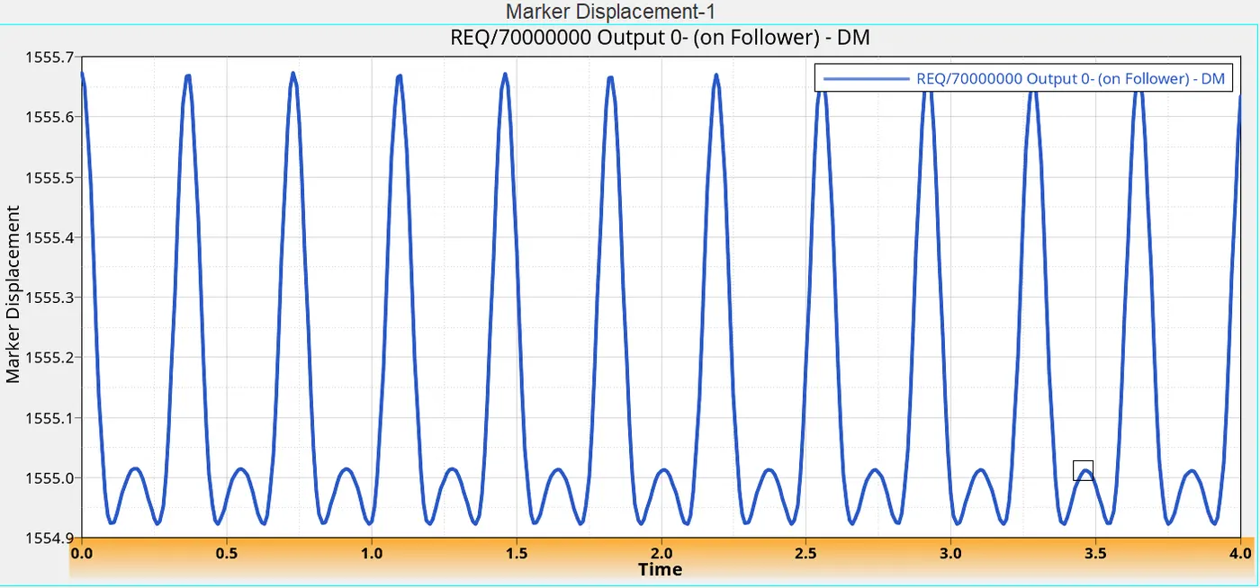
- OUTPUT 0 : We created a displacement ouput of the follower . We selected the entity to get analysed .

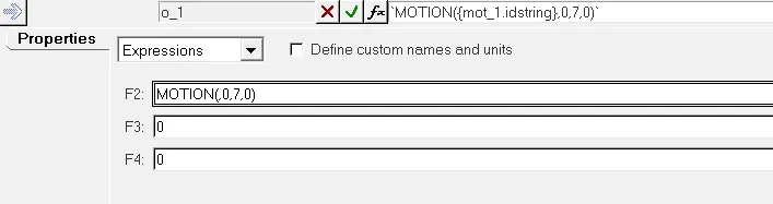
- OUTPUT 1 : We used MOTION Function to calculate the torque along the axis of revolute joint 3 .
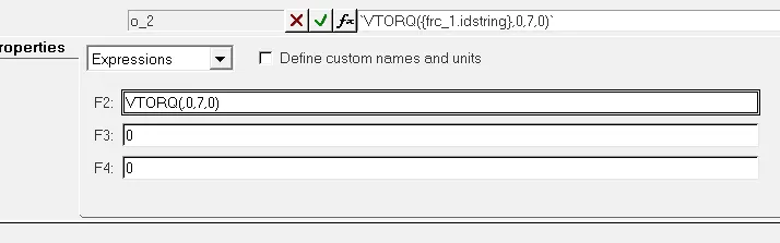
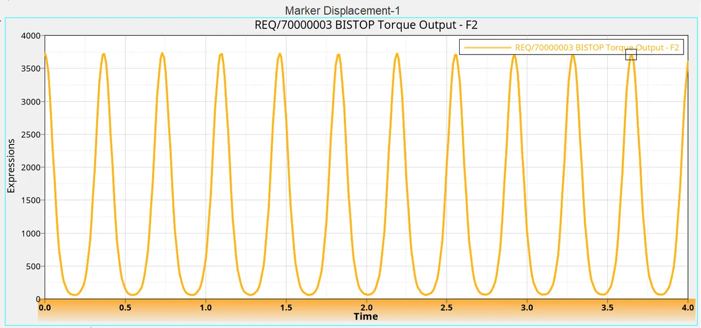
- OUTPUT 2 : We used VTORQ Function to calculate the y component of the torque at the joint 3 which is caused by the BISTOP Function .
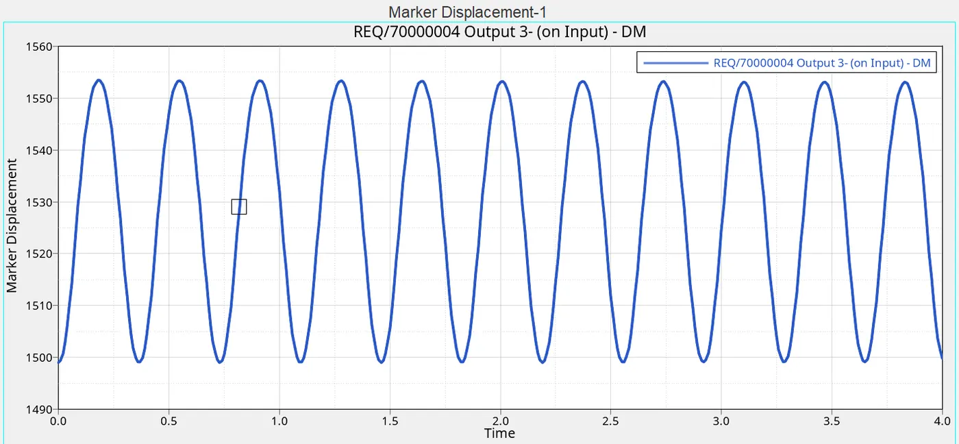
- OUTPUT 3 : We used it to calculate the dislpacement of the tip of the trunk lid which is situated at point I with respect to the ground .

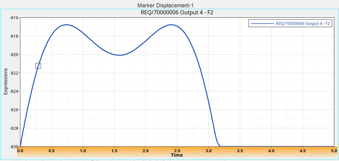
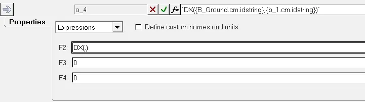
- OUTPUT 4 : We used DX function which is used to calculate the displacement of the I marker wrt to J marker . Here , the COM of the input link is analysed.
DX (I,J,K)
I : marker whose displacement is to be computed.
J : marker with respect to which the displacement is to be computed.
K : resultant displacement vector is resolved in the coordinate system of the K marker. This argument is optional. If omitted, it defaults to the ground coordinate system.
RESULTS
BISTOP : HERE I WILL EXPLAIN ONLY IMPORTANT OUTPUTS BRIEFLY .
- OUTPUT 0 : THE FOLLOWER GETS MAXIMUM DISPLACEMENT WHEN THE TRUNK LID CLOSES . THE CURVE GETS WAVY WHEN THE TRUNK LID REACHES THE MAXIMUM HEIGHT BECAUSE AT THAT TIME THE TRUNKLID JUST STOPS AND GETS DOWN TO ITS CLOSING POSTION.
- OUTPUT 2 : The bistop torque becomes maximum when the trunk lid is just about to close and is minimum when it reaches its maximum height . The BISTOP Function tries to close the trunk lid when it is just about to reach the BIW Fixture of the model , it works against the gravity to stop the lid , thats why it reaches the maximum value .
- OUTPUT 3: The displacement graph of the tip of the lid .
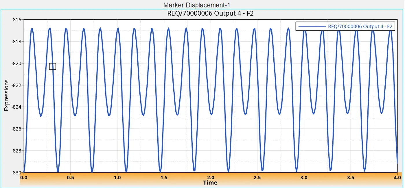
- OUTPUT 4 : The displacement of COM of input link . The displacement value becomes maximum when the trunk lid reaches maximum height .
CURVE :
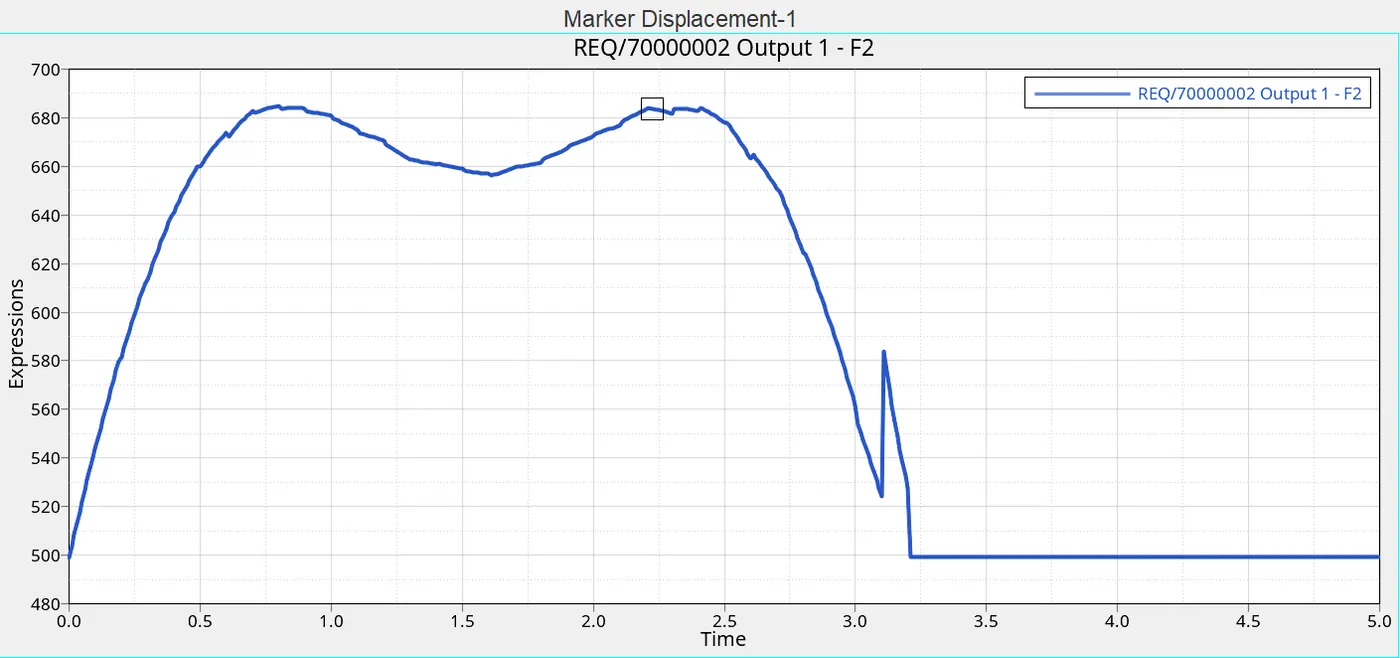
- OUTPUT 1 : This is the torque at the joint 3 when we are using curve . It is very interesting to see the curve which is looking like a smooth curve but it is actually having some sharp ends througout its path . It is because of the less sufficient data points of displacement , in place of which the other values are generated using the Interpolation technique ' AKIMA' which has also has some drawbacks in generating smooth curves . Interpolated displacement data making the motion follow it , thus causes jerky torque movements .
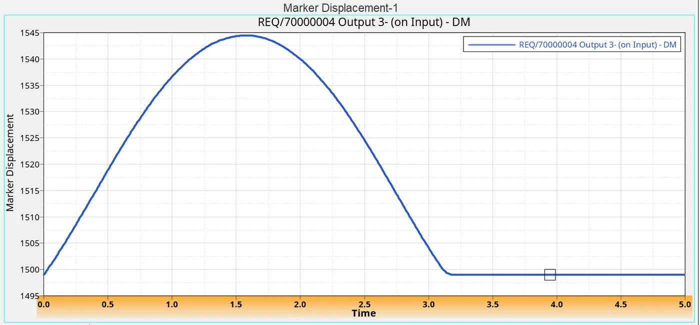
- OUTPUT 3 : Simple displacement graph of the input link tip . You can also genrate this graph in excel .
- OUTPUT 4 : The displacement of the COM of the INPUT link . You can see a curvy slope at the top of the graph which has small depression during the time interval of 0.75 sec to 2.4 sec ( approx ). As we can see in animation the trunk lid at that moment just stops to descend back into the descending position of the car , there is a little decrease in the displacement .