Modelling of 25 storey building with the specified properties using ETABS
Model a 25 story building on ETABS with structural properties as specified below. Ground floor or plinth floor level can be taken at a height of 1.5 metres from the base. Each of the successive 25 storeys has a storey height of 3 metres.
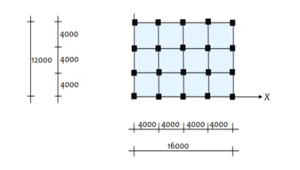
Structural Element Sizes
- Beams : 300 × 400 mm
- Columns : 800 × 800 mm
- Slab : 150 mm thick
Material Properties
- Grade of Concrete : M30
- Grade of Steel Reinforcement Bars : Fe 415
Loading
- Dead Load on beams from infill wall : 10 kN/m (Let us assume the same for roof floor in view of parapet)
- Live load on floor : 3 kN/m2 (Let us assume the same for roof floor)
a) Buildings are assumed to be pinned at the base
b) All columns in all storey are of the same size
c) All beams in all storeys are of the same size
d) Building is located on Soil type-II and in Zone-III. Assume other factors if required.
ANSWERS:
COMPLETE STEPWISE PROCEDURE TO MODEL A 25 STORY TOWER IN ETABS
- Start the Software and Setup the New Model
- Start the ETABS software from the desktop shortcut or by searching in the start menu.
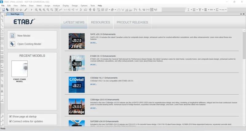
- Then, the ETABS intro page will be displayed on your screen. Look for the new model option present on the left side of the screen.
- Once you click on the new model option, you will be required to set up some basic details pertaining to the project.
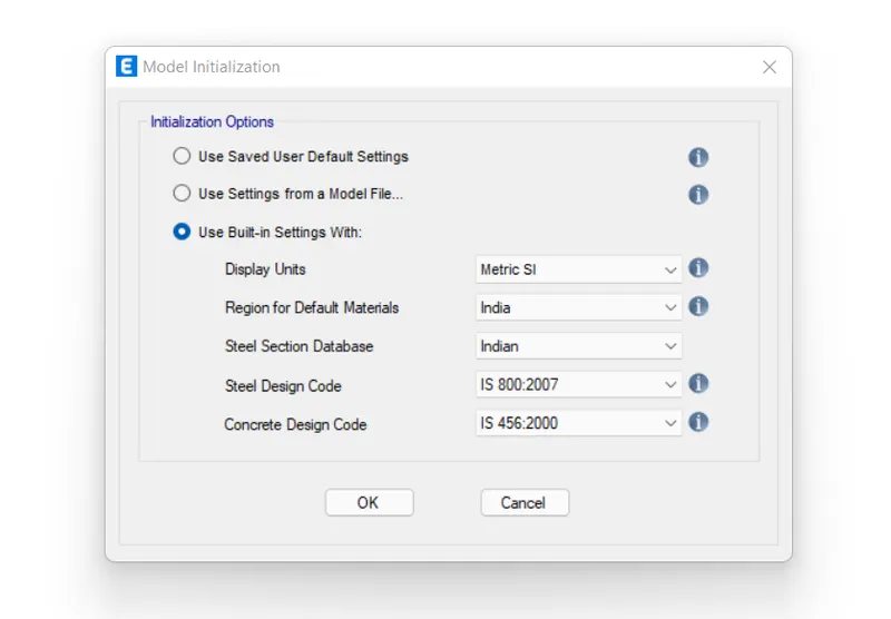
- You can fix the standard codes you will be using for the design from the dropdown list that pops up when you create a new model in ETABS.
- So, the same was done and the new model for our 25 story tower was initiated as inserted below:
- Setting up the Grid and Story Data for the Project
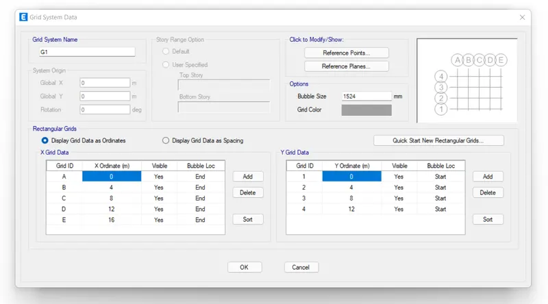
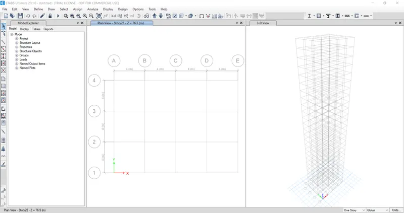
- After starting a new model in the software, you can set up the grid locations as per the Architectural drawings received.
- And in our case, we have been given a 5x4 grid system with 4 meter uniform spacing in-between.
- So, select the custom grid option and specify the number of grids with the total relevant spacing in-between and form a grid system for the ETABS model.
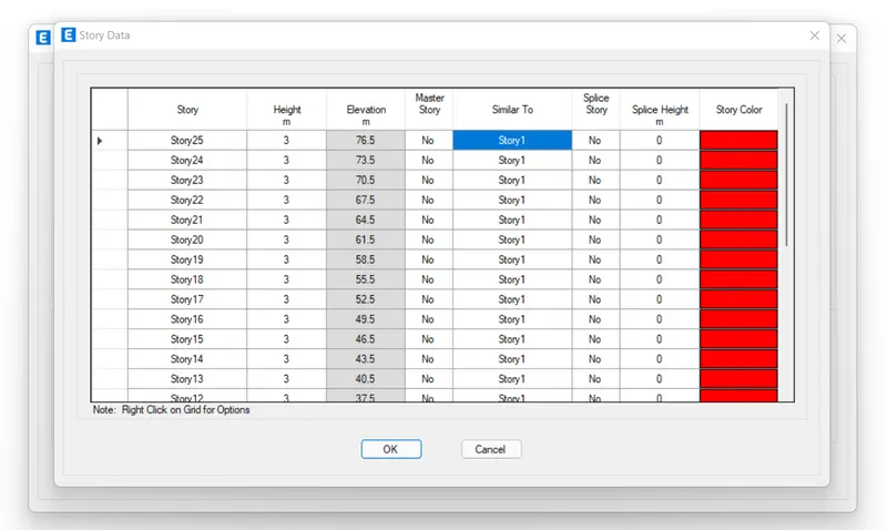
- Similarly, go to custom story data and insert the total 25 stories as required for our project with each story height of 3 meters.
- Also, set up the plinth from the base at the height of 1.5m.
- And, make the first floor as the master story and all remaining floors as similar floors to that of the first story.
- Define Material Properties
- After setting the grid and story data and before executing the modeling part, we need to specify the material properties we will be needing for our project.
- And as specified in the question, we need M30 grade concrete and FE415 steel for this model.
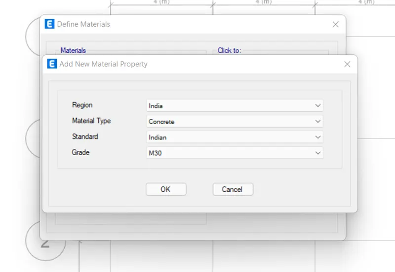
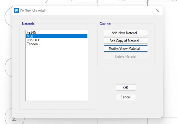
- So, go to define>material properties> add new material.
- Now from the dropdown menu, select India as the region, concrete as the material type and Indian standard with M30 grade.
- Follow the same procedure and define the HYSD 415 steel.
- Define Section Properties
- After defining the materials, we now need to go ahead and set the details for beam and column sections as well as the slab we need for our 25 story model.
- And to do that, again go to define then select section properties and choose frame sections.
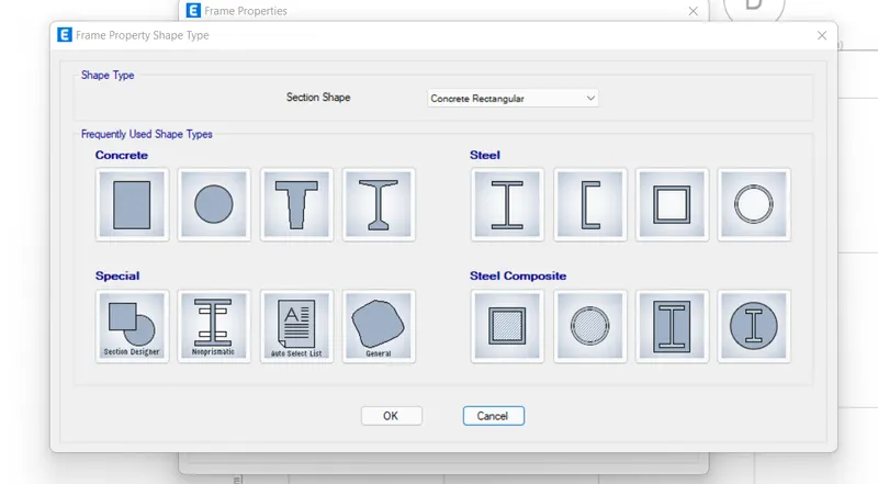
- Then, select the concrete rectangular section from the list of different section shapes.
- Now, set up the grade as M30 and give column dimensions as 800 x 800.
- Similarly for beams, enter the dimensions as 300 x 400 as specified in the question.
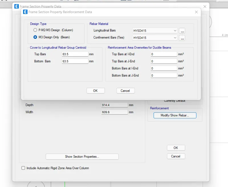
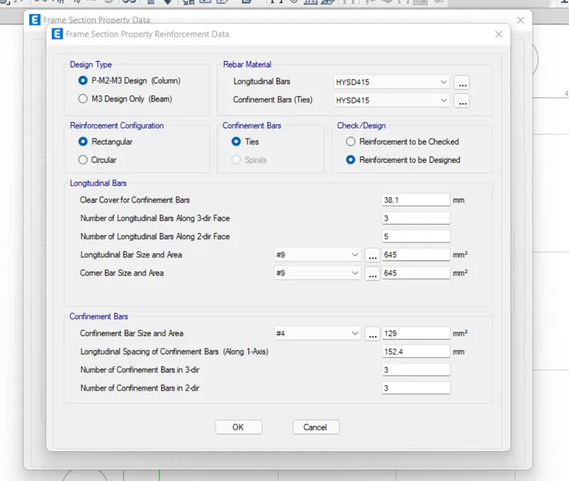
- Then, go to reinforcement details and set up the the standard reinforcement for beams and columns.
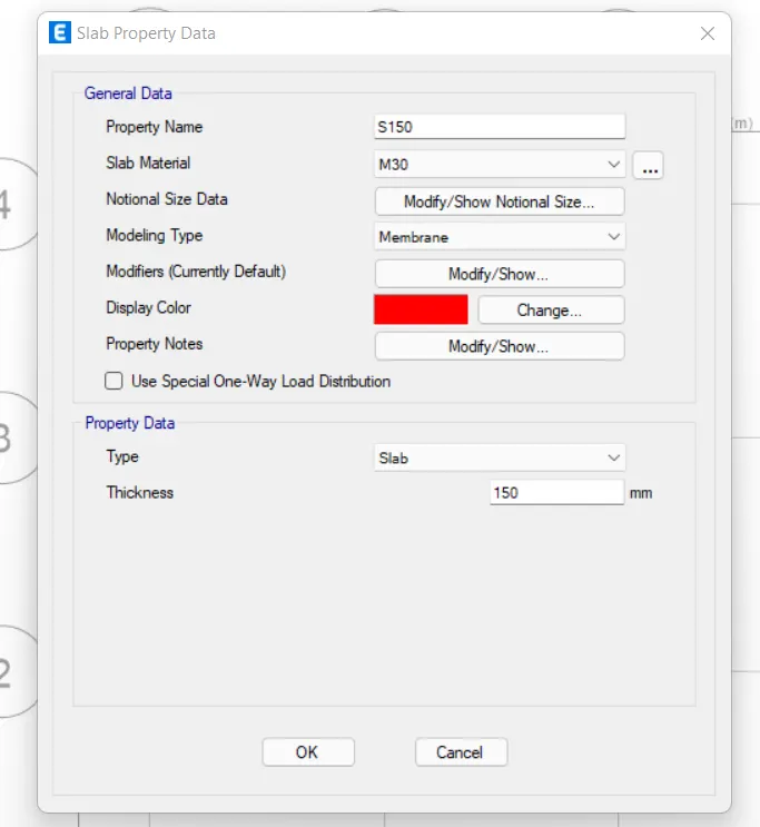
- Now, again go to the define>section properties and select slab sections.
- Then, choose the slabe type as membrane and specify the thickness as 150mm as specified in the question.
- Execute the Modelling
- Now that we have specified the sizes and type of frame and slab to be used for our project, we can start the modelling phase in ETABS.
- So, there are number of ways ETABS allows you to model the structural element for your project.
- One of the ways is called quick draw tool. This tool allows you to quick draw beams/columns and floors at specified locations on your grid system.
- Therefore, the same tool is used and the all the beams, columns, and slabs are modelled as per our grid system.
- Also, make sure to use proper one story, similar story, or all stories options available at the right hand side bottom of your ETABS screen while modelling the structural elements.
- For example, columns will be modelled at all stories while slabs shall be done for the similar stories as there's no slab at the base of plinth of the building.
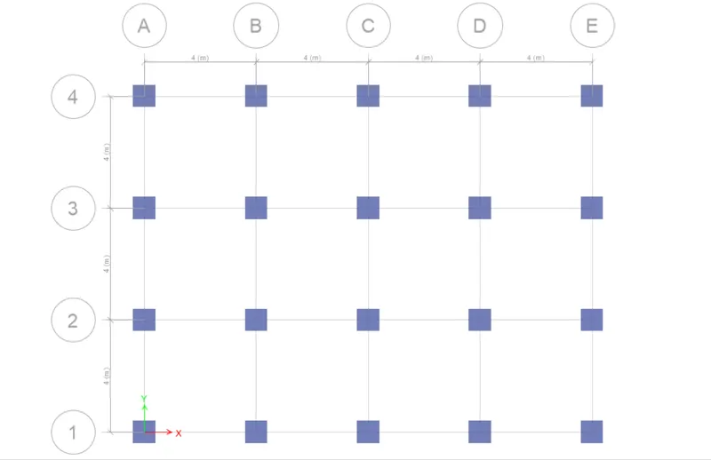
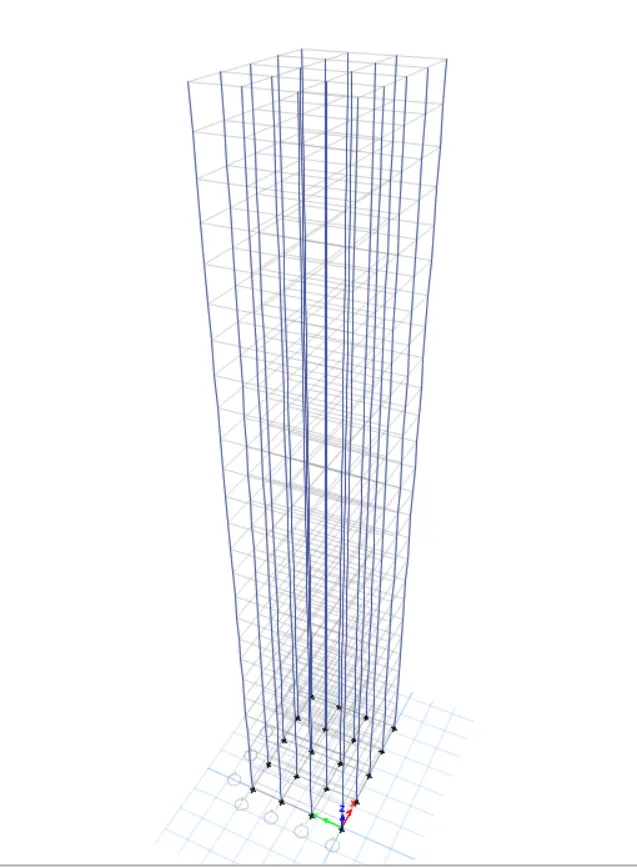
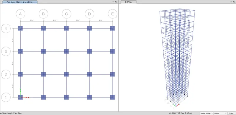
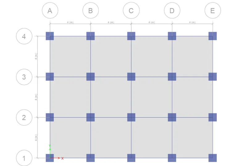
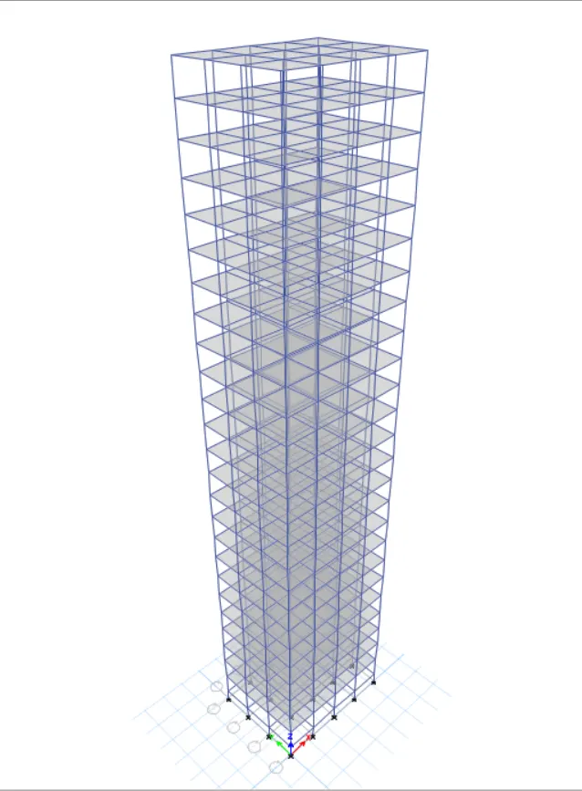
- Thus, all the beams, columns and floors were drawn and the following model was prepared in ETABS.
Columns Modelling
BEAMS
SLABS
- Defining Load Patterns
- After completing the modelling part, now it's time to define all the loads that our is model is expected encounter.
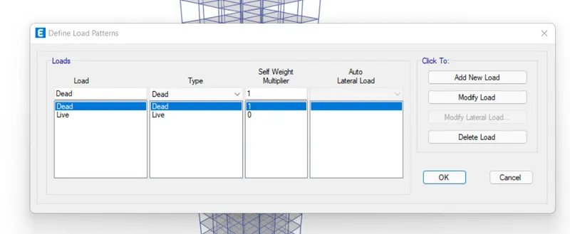
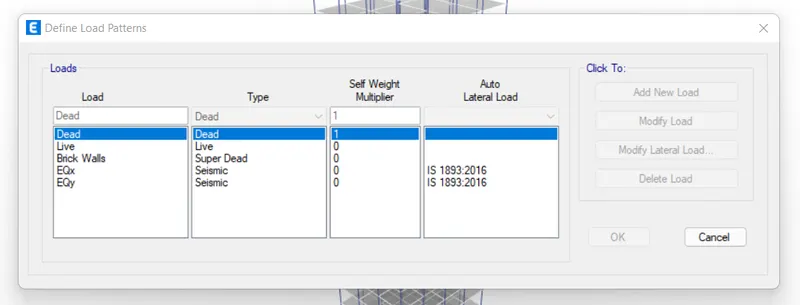
- So, go to define>load patterns and a dialogue box will open up that will contain all the load cases that you can define for your project.
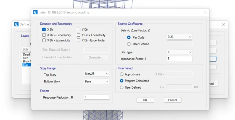
- From the same menu, choose the dead load, super dead load (Brick wall load), and the earthquake load in both the orthogonal directions.
- Define Mass Source
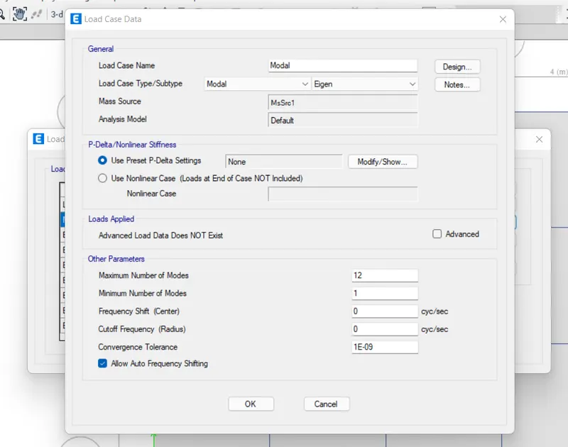
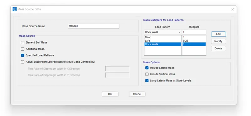
- In order to run the seismic analysis for a building, we need to define the relative seismic weight of the building which is also known as the mass source.
- So, to define mass source in ETABS, go to define> mass source.
- Now, modify the mass source and add up the values to be included in the seismic weight of the structure.
- And according to the codes, total seismic mass of the building includes 100% of dead load, super dead load and 25% of the live load present on the structure.
- Generate Load Combinaitons
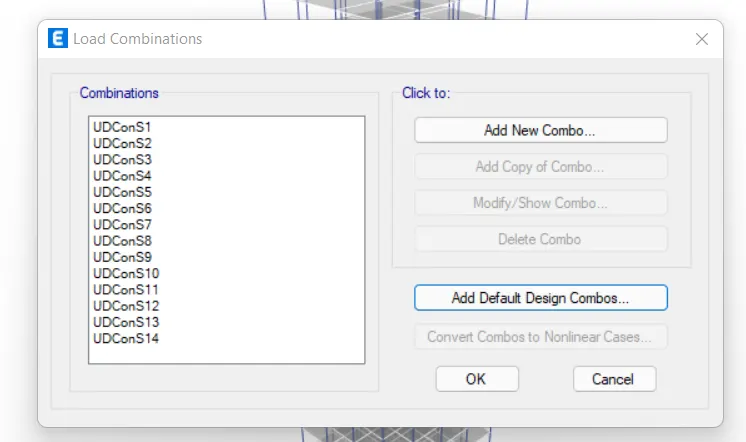
- To generate load combinations, go to define>load combinations.
- Then, select on add default dsign combos.
- Check the concrete frame design and click on ok button to generate the default load combos.
- Assign the Frame and Shell Loads
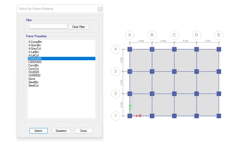
- To assign loads, we first need to select the section on which we are assigning the loads.
- So, go to select>section>B300x400 to assign the superdead load as specified in the question.
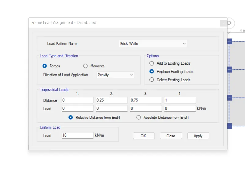
- After selecting the beam section, go to assign then frame loads.
- A dialogue box will open where you can specify the type and intensity of loading.
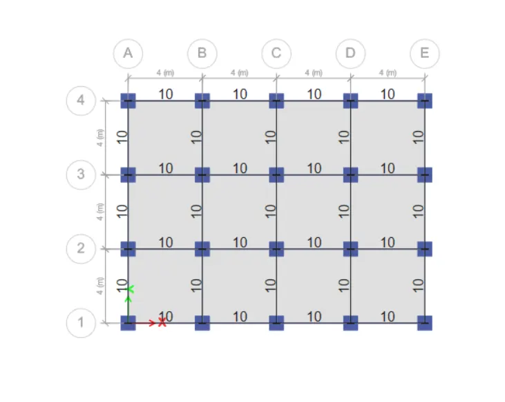
- And as given in the question, beam sections are subjected to a uniform loading of 10 KN/m due to the super dead load imposed by the brick walls.
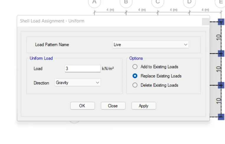
- Similarly, a uniform shell load of 3 KN/m^2 is to be assigned for all the slab sections.
- Assign the Diaphragm
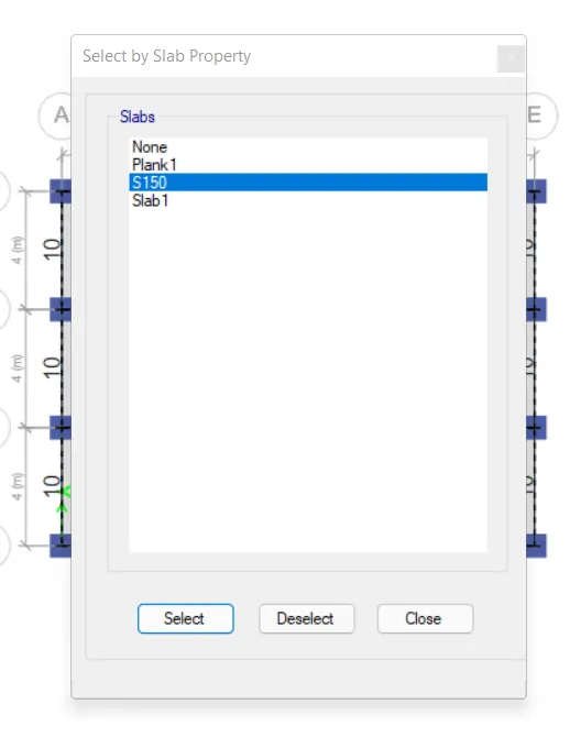
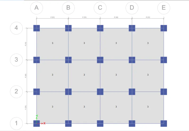
- Go to select>section>slab section>S150.
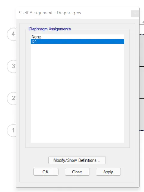
- After selecting the slab, go to assign and click on the diaphragm.
- Now, select the D1 from the diaphragm list.
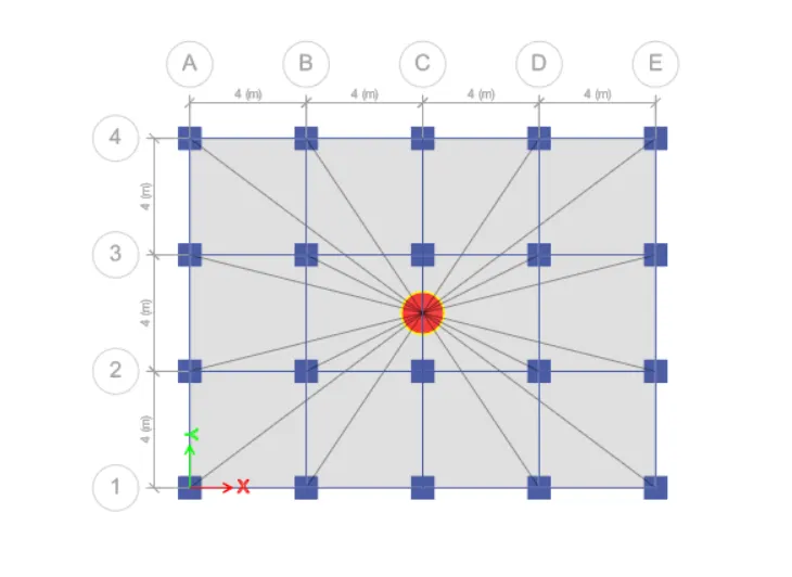
- The center of mass for our building will be automatically generated after assigning the floor diaphragm.
- Run the Analysis
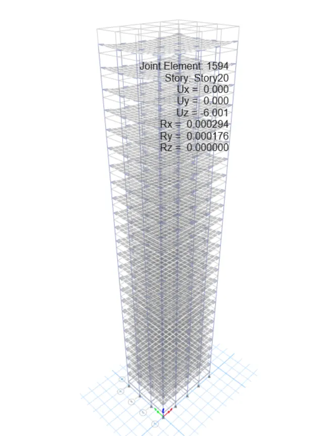
- You can go to the Analysis tab and run it from there or either you can simply press F5 on your keyboard and the ETABS will run the analysis for you.
- Wait for the analysis to complete and the building to take the deflected shape.
- Generate the Output
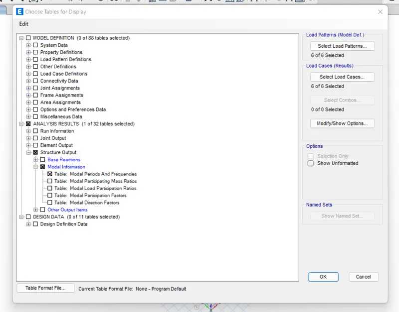
- Now after successfully running the analysis, go to display and show table.
- A list in a tree format will appear from where you can generate the results of your choice as per the analysis.
- So, go to the structural output>modal information>modal periods and frequencies.
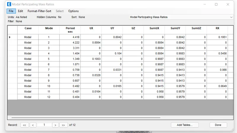
- Similarly, do it for the modal participation ratio and the maximum inter-story drift.
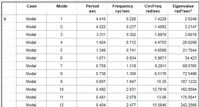
MODAL RESPONSE TABLE
MODAL PARTICIPATING MASS RATIOS
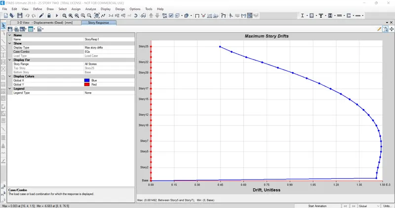
MAXIMUM STORY DRIFTS DUE TO EQx
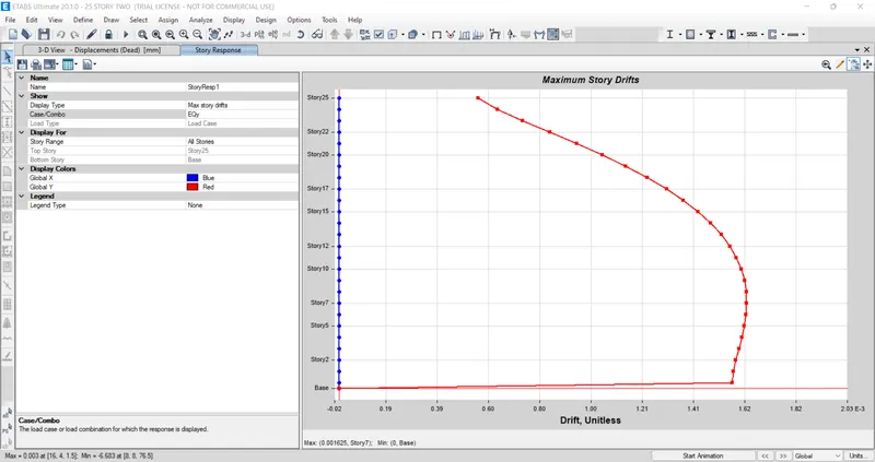
MAXIMUM STORY DRIFT DUE TO EQy
Analysis Related Q&A
- Check if the translational fundamental natural period of vibration in both the x and y direction is approximate: Tx1= 4.4 seconds Ty1= 4.2 seconds
ANS:
As can be seen from the table inserted for the modal response, the first modal period (Tx1) = 4.416 and the second modal period (Tx2) = 4.222. Therefore, YES! the translational fundamental natural periods of vibration in both the x and y directions are approximate to the desired value.
- Check if the following provision in Table 5 of IS 1893 (part 1) – 2016, on torsional irregularity is satisfied:
The natural period corresponding to the torsional mode of oscillation must be less than the two fundamental translational modes of oscillation along with each principal plan direction.
ANS:
YES! The natural period corresponding to the torsional mode of oscillation is less than the two fundamental translational modes of oscillation along with each principal plan direction. T1 = 4.416, T2 = 4.222 > T3 = 3.311
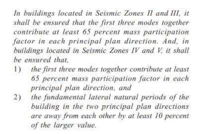
- Check if the two provisions of clause 7 in Table 6 (shown below) of IS 1893 (part 1) – 2016, regarding vertical irregularity is satisfied
ANS:
The table for modal mass participation ratio has been inserted which showcases that around 80% of the mass accounts in the first three fundamental modes. Hence, the first provision of clause 7 is satisfied.
However, the second provision which specifies that there should be a difference of at least 10% between both the fundamental lateral natural periods of the building in the two principal plan directions is not satisfied for our model. We have T1= 4.416 and T2 = 4.222 and clearly, the difference between these values is not more than 10%.
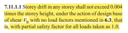
- Check if the provision on inter-story drift limitations in clause 7.11.1.1 is satisfied. Please note that this check is for Serviceability Limit State and hence is for situations when the structure is subjected to unfactored seismic base shear
ANS:
There are two graphs inserted in the project which represent the maximum story drift at all levels due to the forces EQx and EQy. And we can see from the graph that the above condition for the inter-story drift has not been satisfied in both cases.