Modelling of 25 storey building with the specified properties using ETABS
Aim - Model a 25 story building in ETABS by the given properties.
Procedure
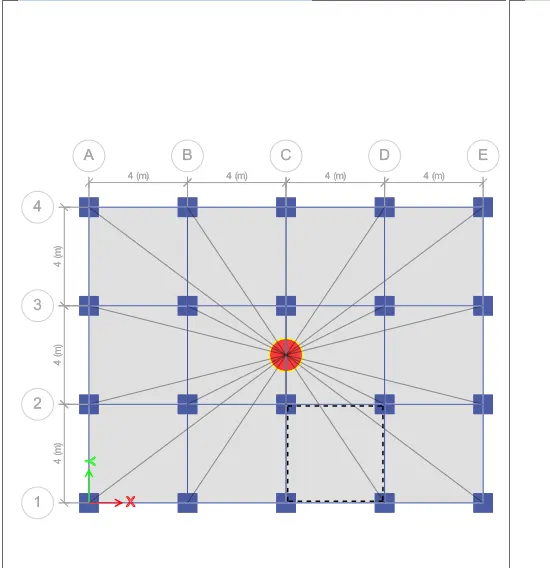
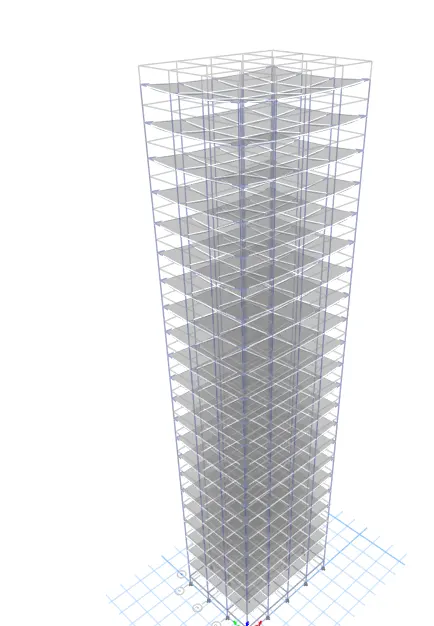
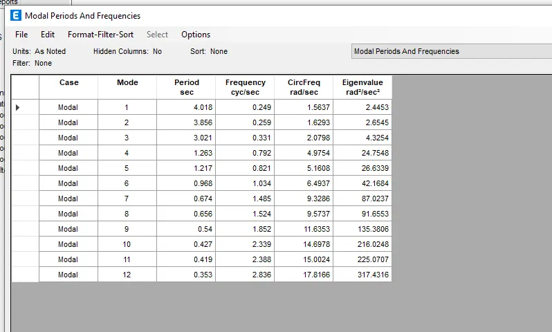
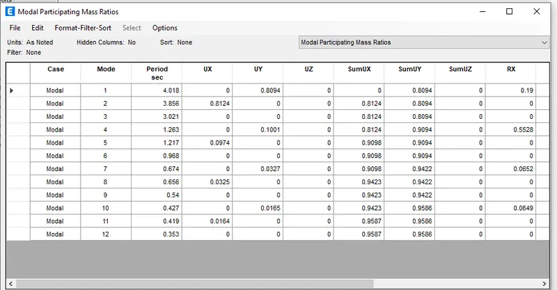
Open a new model in etabs
Give units as metric SI
Steel as indian
Design code as IS 800 : 2002
Concrete design IS 456 : 2000
Then give grids and story data
Give spacing in X and Y direction for the grids
Then gove story data
From base to plinth give height as 1.5m and remaining all floors as 3m
Give story 1 as master story
Then give remaining all as similar to 1st story
Give material properties
In the define tab go to material properties
Add new material India concrete and grade as M30
Again add new material
Material type as rebar , indian standard and grade as FE415
Give beams,coloumns and slab
In the define tab select sectional properties and framed sections for beam and coloumns
Add new propert and rectangular concrete
Give property name as B300x400
Give depth as 400 and width as 300 as given
In the same process add new propert as coloumn and name it as C800x800
Give depth as 800 and width as 800
For slab
In the define tab select sectional properties and select salb sections
Add a new property
Then rename as S150 and give modelling type as membrane and give thickness as 150 and OK
Then start modelling
Go to any plan view and select all stories
Select quick draw coloumns and select C800x800 and draw at the grid points
Then select quick draw beams and select B300x400
Then draw beams at the grid lines
You can also replicate the beams and coloumns by giving offset and no of times
Add slab
First select similar stories
Go to any plan view and select quick draw floors and select S150
Select the space where slab to be laid
Then assign the loads
In the define tab select load patterns
Select dead load with multiple of 1
Add live load of multiple 0
Wall load as super dead load and multilpe 0
Eq in X directiion of seismic load and code of IS 1893 2016
Eq in Y directiion of seismic load and code of IS 1893 2016
Then select Eqx and modify and select zone as 2 and I factof as .16 same for Eqy
Then OK
Assign live loads
Select all the slabs
Then assign shell loads and uniform loads and as live and give value of 3KN/M
Then assign wall loads
Select all beams
Then assign and frame loads
Then UDl and give value as 10
Mass source
For earthquake load we have to assign mass source
Define and mass source
Select specefied load pattern and Ok
Now generate load combinations
Define tab and load combinations and select default design combinations
Then select concrete frame design and edit table and OK
Diaphragm
Select all the floors
In the assign tab and shell tool and select diaphragm
You can see the eccentricity of the structure which is useful in lateral loading
We can check the model cases in define
Then analyse the structure by clicking run analysis key
Go to tables in the left side
Analysis result and structural output and model oinfo
Vibration in X and Y direction
Model periods and dispaly tables
Model 1 - 4.01
Model 2 - 3.08
Which is approximately equal
Torsional deviations
Torsional mode time period is less than X and Y direction time period
X - 80%
Y - 81% (yes)
Fundamental natural periods are almsot equal not less than 10% (NO)
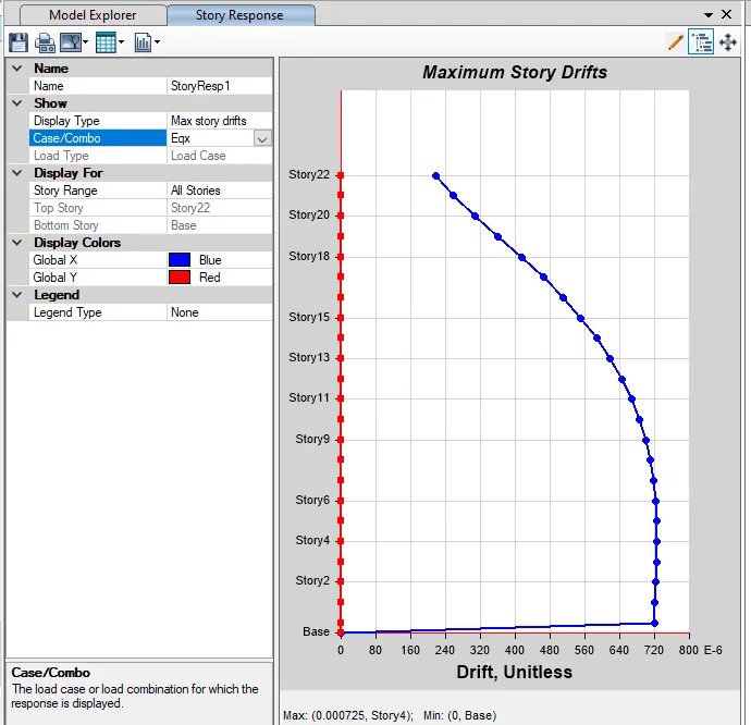
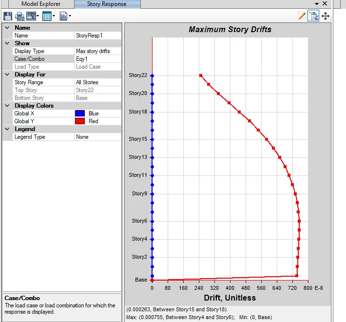
Interstorey drift
It should not exceed 0.004 times height of building
The valus is almost same as we see in the graph