Modelling of 25 storey building with the specified properties using ETABS
- Aim: To Model a 25 Storey on ETABS With structural Properties as Specified Below. Ground Floor or Plinth Floor Level Can Be Taken at a Height of 1.5 Meters from the base. Each of the Successive 25 storeys has a storey height of 3 Metres
- Structural Element Sizes:
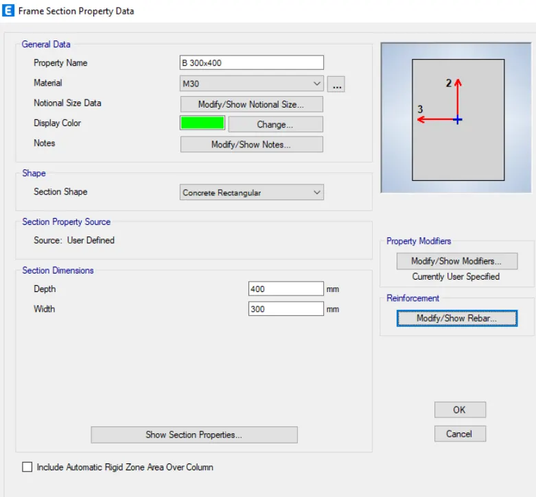
- Beams: 300 × 400 mm
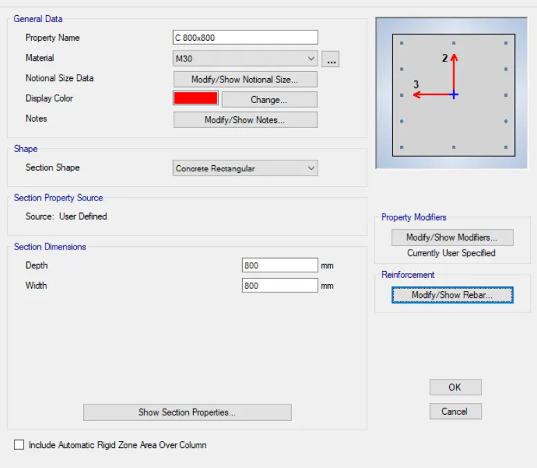
- Columns: 800 × 800 mm
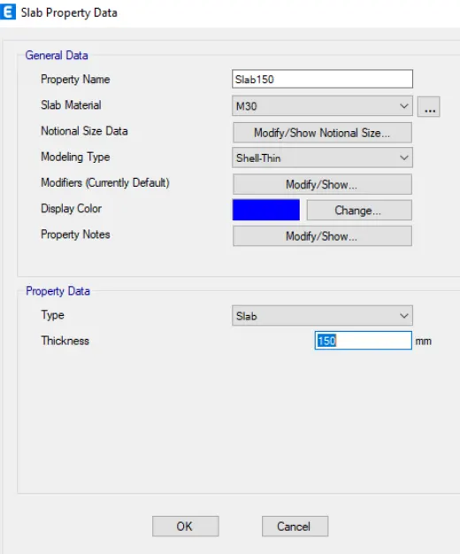
- Slab: 150 mm thick
- Material Properties
- Grade of Concrete : M30
- Grade of Steel Reinforcement Bars : Fe 415
- Loading
- Dead Load on beams from infill wall : 10 kN/m (Let us assume the same for roof floor in view of parapet)
- Live load on floor : 3 kN/m2 (Let us assume the same for roof floor)
- a) Buildings are assumed to be pinned at the base
- b) All columns in all storey are of the same size
- c) All beams in all storeys are of the same size
- d) Building is located on Soil type-II and in Zone-III. Assume other factors if required.
- To Carry out the following exercises:
- Check if the translational fundamental natural period of vibration in both the x and y direction is approximately:
- Tx1= 4.4 second Ty1= 4.2 second
- This check will help confirm if modelling is done correctly. Some deviations from the above values is possible (± 2%). But any major deviation will suggest an error in modelling.
- Check if the following provision in Table 5 of IS 1893 (part 1) – 2016, on torsional irregularity satisfied:
- The natural period corresponding to the torsional mode of oscillation must be less than the two fundamental translational modes of oscillation along each principal plan directions.
- Check if the two provisions of clause 7 in Table 6 (shown below) of IS 1893 (part 1) – 2016, regarding vertical irregularity is satisfied
- Procedure:
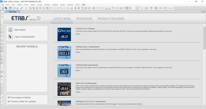
- Open the ETABS Application and Click on the New Model Option From the File Menu
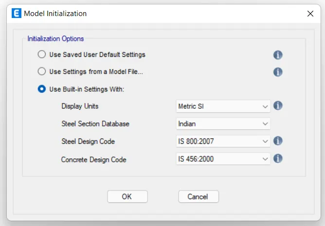
- Now in the Model Initiation Window Desired Units, Design Codes Which are to be Used was selected and then Click ok
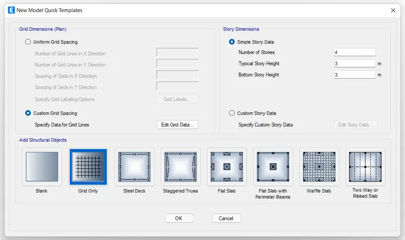
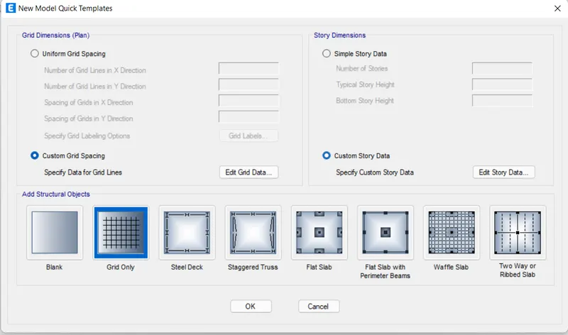
- In New Model Quick Templates Under Grid Dimensions Select the Custom Grid Spacing and then Click edit Grid Data
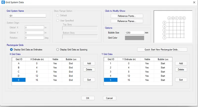
- The Grid dimensions Was Inserted according to question as follows and Click Ok
- In New Model Quick Templates under Story dimensions Select the Custom Story Data and then Click Edit Story Data
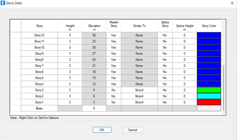
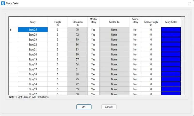
- Now Input the storey Details as given In Question and Story 1 was Selected as the Master Story and was applied to rest story From 2nd Story to roof and then Click ok.
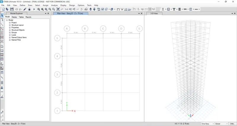
- The Plan and 3D View of all the data’s Which we have given till now is shown on the Image Below
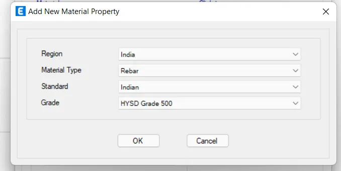
- Now to Define the Properties of elements go to define menu and then select Material Properties. The Grade of Concrete was Selected and Click ok
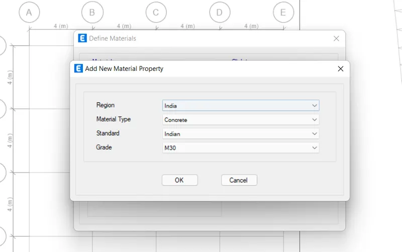
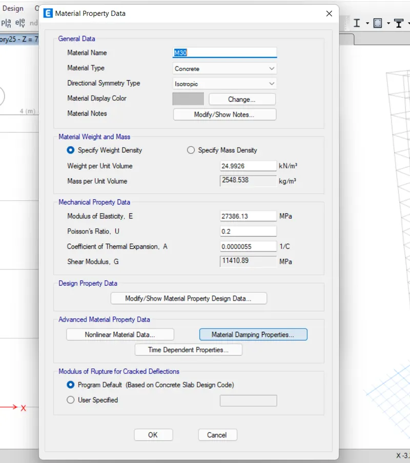
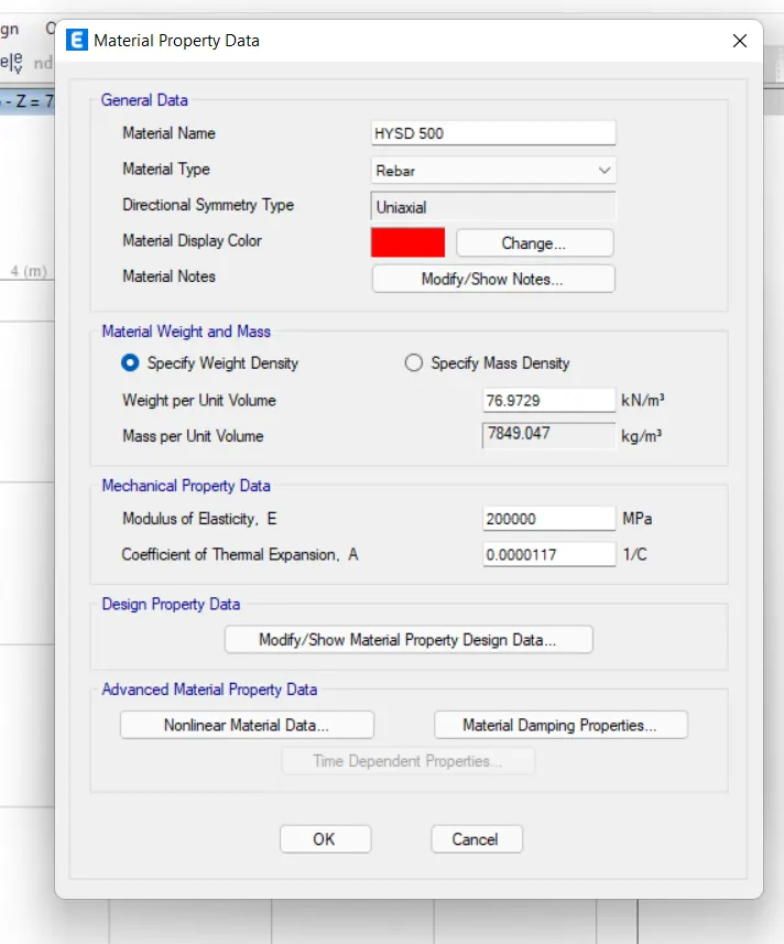
- The Material Property data Dialogue Box will Show Up Ensure all the data’s are Correct and then Click Ok at the Bottom
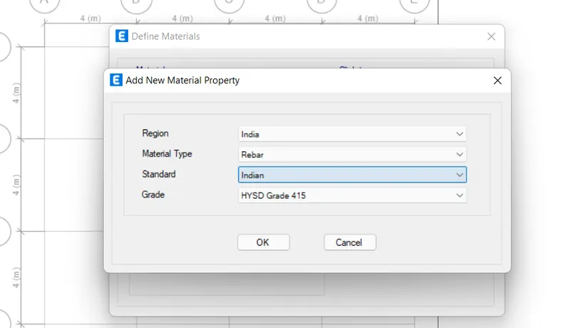
- Similarly HYSD 500 and HYSD 415 Steel Was Added
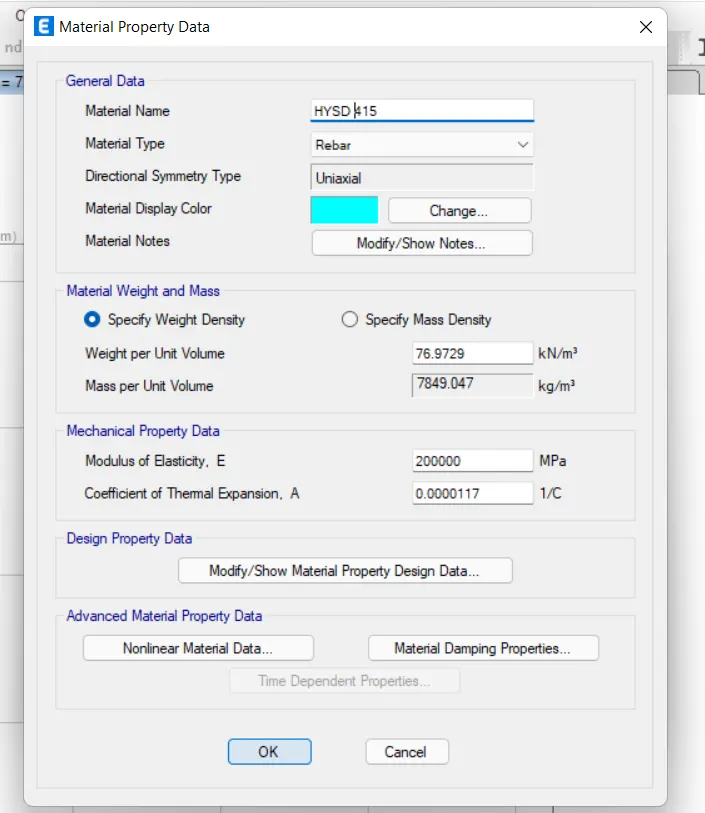
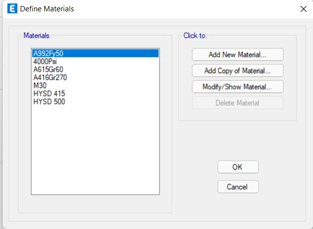
- Steel and Concrete properties was added to the list now as shown and then Click Ok
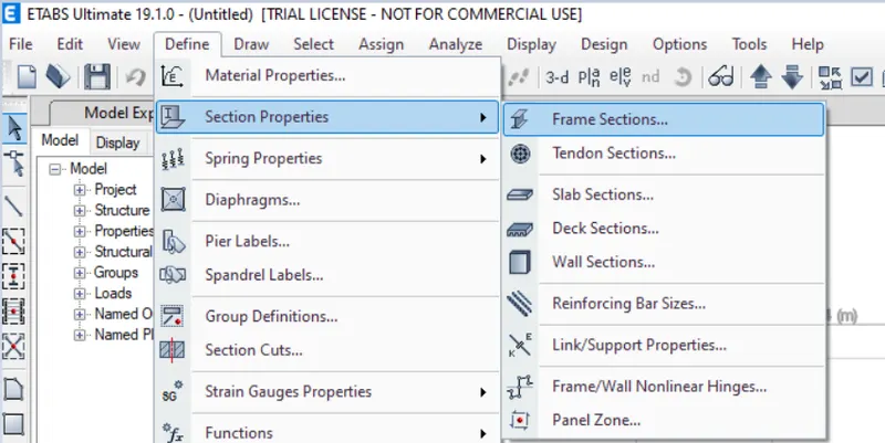
- Now, We Need to add the frame Members I.e. Beams, Columns and Slabs. Go to Define Tb>Section Properties>Frame Sections
- Frame Properties window Opens and in that go to add new Material Property
- The Reinforcement Details and Cover to the Reinforcement is also Provided
- Similarly add Column to the list by providing the reinforcement details
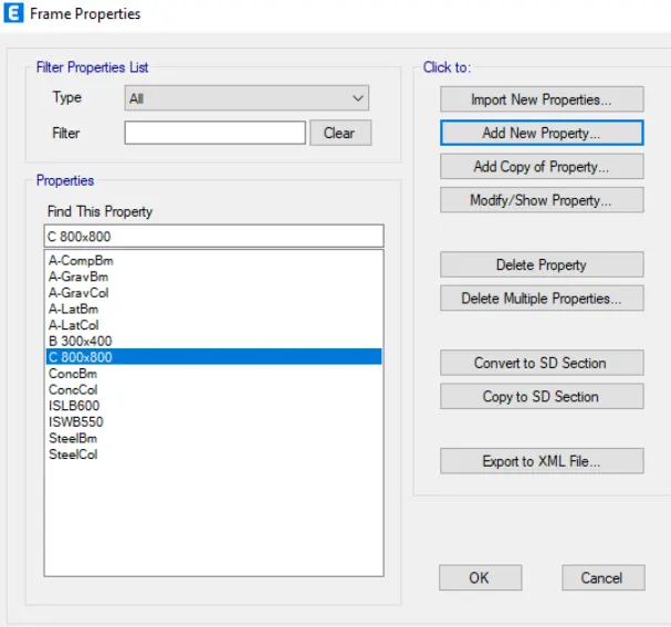
- Hence the Materials added to the list is as given below
- Next we have to add the slab details. For this go to define tab> section Property> slab sections. Box Opens in the edit the Slab Properties
- So all the Properties Frame members have been added correctly, now we have to place the structural Members
- For this choose quick draw column option from the tools available at the left side of the screen and place the columns at all the grid intersections
- Since columns extends throughout the height of the structure so care should be taken to check whether columns are assigned to all storeys
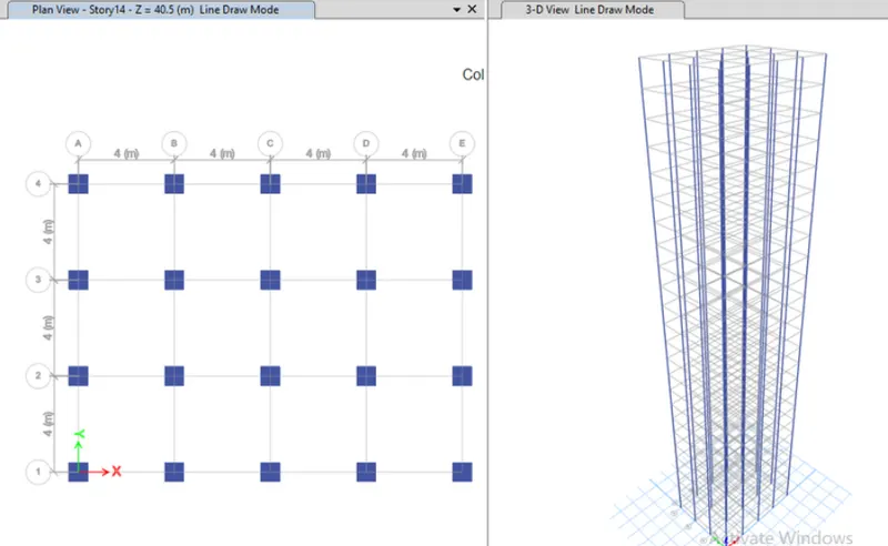
- Next we have to place the position of beams, for this also quick draw beams option can be choosen
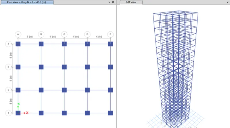
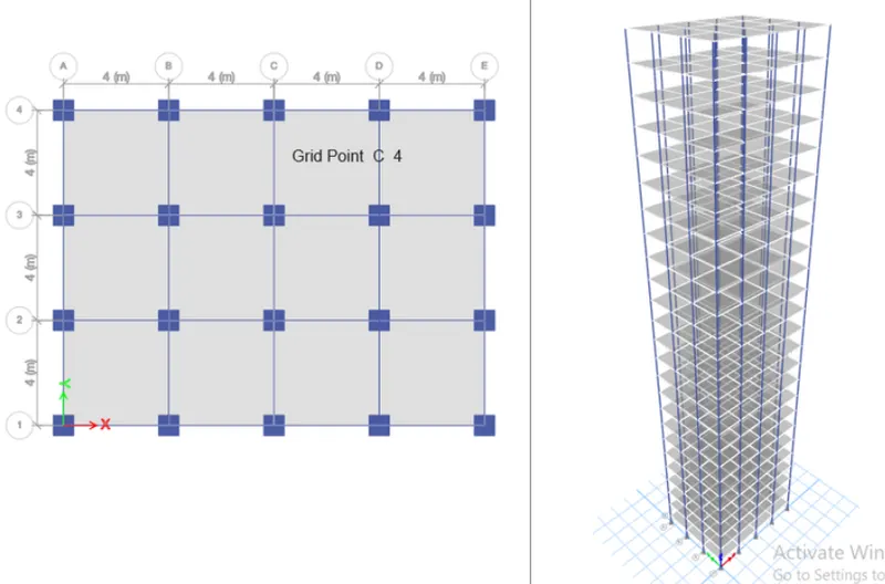
- Now we have to create the slabs for this initially change the all storeys option to similar storeys which may exclude the base
- Then choose quick draw floor or wall option to easily draw the floor slabs
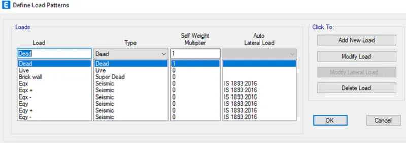
- Next we have to assign loads to the frame for this go define tab>Load Patterns> Define Load Patterns Dialogue box appears. Then apply the Loads .
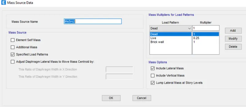
- Now Provide the Mass source Value to Calculate the Seismic weight
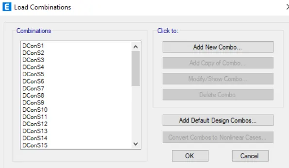
- We Need to define the Load Combination For this Go define>Load Combination. Provided the Default Load Combination Itself
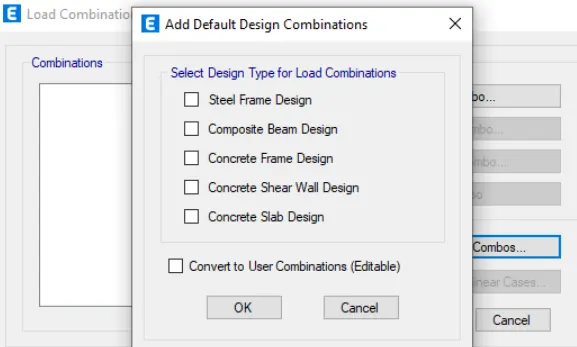
- Choose Concrete Frame Design and Click
- Select all the Floors. Select>Object Type>Floors. Hence all the Floors are Selected
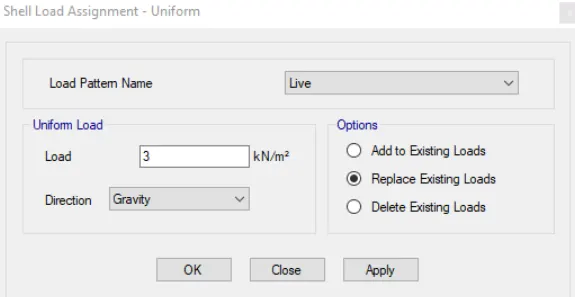
- Then Go to Assign > Shell Loads > Uniform> Live Loads> 3Kn/m^2>Apply>Ok.
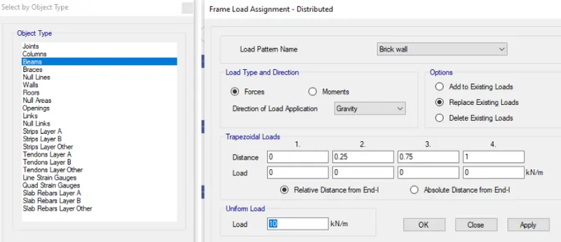
- Select all the Floors Select Object Type Beams . Hence all the Beams are Selected
- Then Go to assign Frame Loads Distributed>Load Patterns>Brick Wall Load>Load>10 Kn/m>apply ok
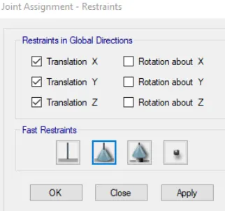
- We have to keep the support as pinned so for this select all joints by keeping in view the base storey
- Then go to assign>Joint>restraint>select Pinned Joint
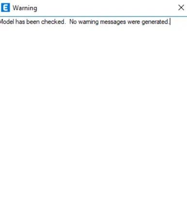
- Go to analysis tab>Check Model>Its Checked for any Errors and Warnings
- Now the Model Can be analysed for this, Go to analysis>run Analysis.
- Hence , analysis has been Completed
- Now, we need to check the details given in the question
- So, for this initially go to display tab show tables>analysis result>Structure Out put>Model Information> Model Periods and Frequencies
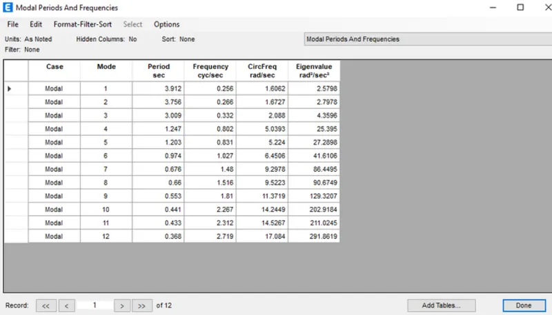
- Check if the translational fundamental natural period of vibration in both the x and y direction is approximately: Tx1= 3.7 second Ty1= 3.9 second
- This check will help confirm if modelling is done correctly. Some deviations from the above values is possible (± 2%). But any major deviation will suggest an error in modelling.
-
This check will help confirm if modelling is done correctly. Some deviations from the above values is possible (± 2%). But any major deviation will suggest an error in modelling.
- Check if the following provision in Table 5 of IS 1893 (part 1) – 2016, on torsional irregularity satisfied:
- Tx1= 3.7 second Ty1= 3.9 second
-
Hence its Verified that the natural Period Corresponding to the torsional mode of oscillation is less than the natural period corresponding to two translational modes of oscillation
-
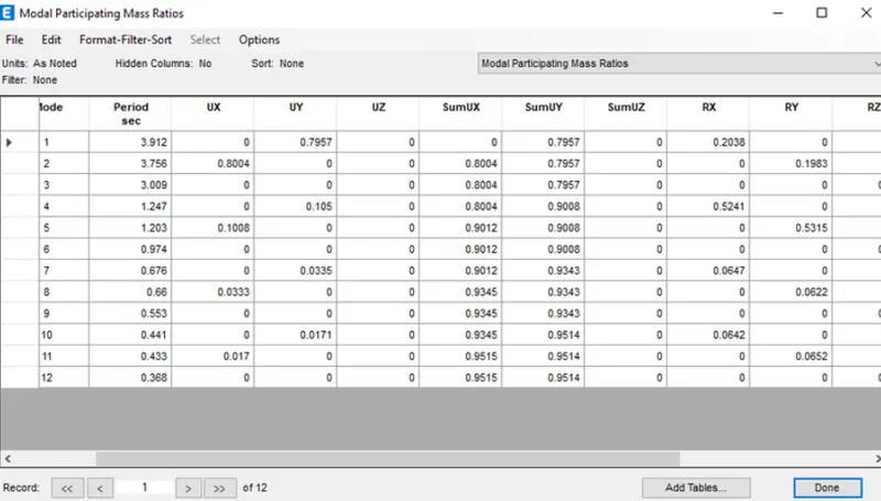
Now model Participation ratios to be taken for this got o display tab>show tables>analysis result>Structure Output>Model Information>Modal Participating Mass ratios
- Check if the two provisions of clause 7 in Table 6 (shown below) of IS 1893 (part 1) – 2016, regarding vertical irregularity is satisfied
- Modal Mass participation ratios of first three modes in x direction is obtained as obtained are
- 1st =0.2038
- 2nd = 0.8004
- 3rd= 0
- Summing these three we get 0.8004+0.2036+0=1.004=100%.65% hence satisfied the Criteria
- Now the Difference between x and Y time Period is Given by 3.912-3.756=0.156=3.98% hence satisfied the Criteria
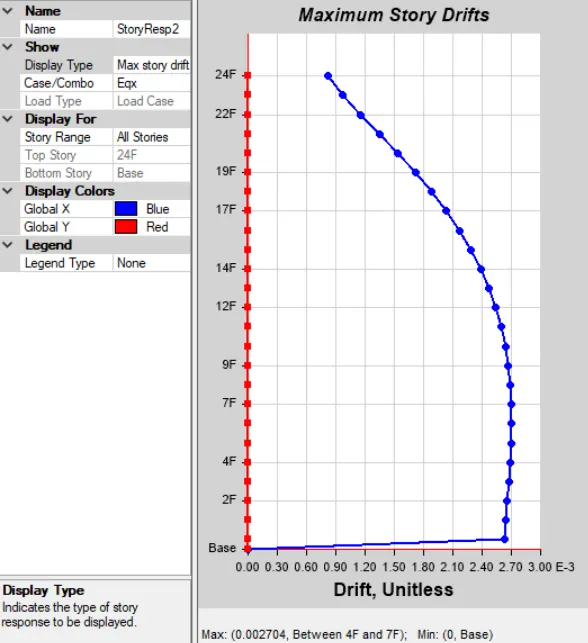
- Check the Provision on inter storey Drift Limitations in Clause 7.11.1.1 Satisfied
- Please Note that this Check is for serviceability limit state and hence is for situation when structure is subjected to unfactored seismic base shear
-
For Obtaining the story drift graph go to display >story response plots>Change the Display type to Max to Story drift> Load Case Combo
-
Here the maximum storey drift obtained is 0.0027 which is less than 0.004 hence local Provision is satisfied
-
Model a 25 storey building on ETABS with structural properties as specified Checks also Carried out. The Structure Satisfies all the Codal