Modelling of 25 storey building with the specified properties using ETABS
Challenge 6 – ETABS modelling of a 25 storey building
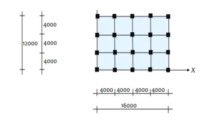
Model a 25 storey building on ETABS with structural properties as specified below. Ground floor or plinth floor level can be taken at a height of 1.5 metres from the base. Each of the successive 25 storeys has a storey height of 3 metres.
Material Properties
- Grade of Concrete : M30
- Grade of Steel Reinforcement Bars : Fe 415
Loading
- Dead Load on beams from infill wall : 10 kN/m (Let us assume the same for roof floor in view of parapet)
- Live load on floor : 3 kN/m2 (Let us assume the same for roof floor)
Solution:
The Above mentioned Project is done as per Is 1893 Part-1 2016 the following procedure is as follows,
Step-1
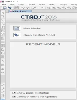
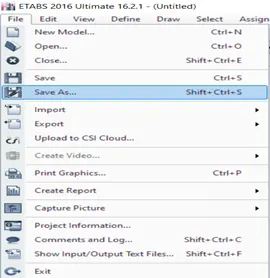
- Open E-tab Software and Select a new file and save the project as Challange 6
Step-2
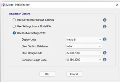
- Now the is step is to set the Model initialization.
- Select the built in option.
- In which select unit as metric SI.
- Steel section database as Indian.
- Steel Design code as IS 800 2007.
- Concrete Design code as Is 456 2000 and press ok as shown below.
Step-3
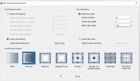
- Now Giving the Spacings of Grids.
- Select grid only option and press ok.
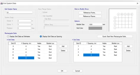
- Now select display grid data as spacing.
- and provide spacing of 4m in x direction and 4m in y direction.
- 5 grids along x and 4 grids along y as mensioned in question.
- As shown below.
Step-4
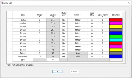
- Select the Storey Data and input the data as mensioned.
- That is select 25 story that is Plinth level and 23 Floors and Roof.
- With 1st floor as master storey and remaining 22 floors as its copy as shown below.
- After completely renaming the Storey press ok.
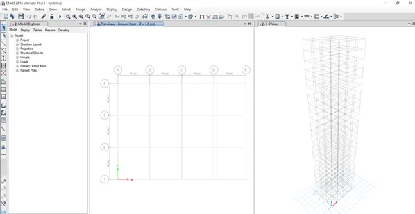
- Now the model will appear as shown below.
Step-4
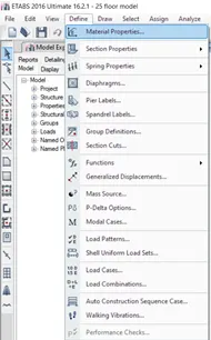
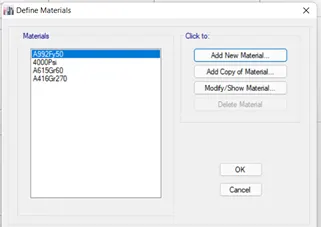
- Now its time to define the materials Properties
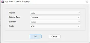
- Select concrete as Indian and M30 grade.
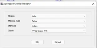
- For steel select Rebars Indian ie HYSD 415 grade.
- After completing Selct ok as shown Below.
Step-5
- Now give Section Properties for Column, Beam and Slab ie.,
- For Column select size as 800x800mm
- For Beam 300x400mm
- And For Slab 150mm thk.
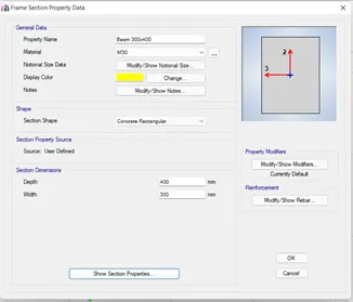
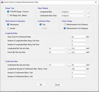
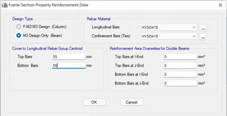
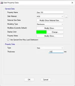
Step-6
- Now placing of Columns and Beams is done.
- select the quick column option and select Column C1 i.e., 800x800 and place it where required.
- Simillarly select quick beam and select the grids where beams are required.
- and also select quick slab selection and place the slab of given size i.e., 150mm thk.
- And Must be noted that the all storeys option should be selected.
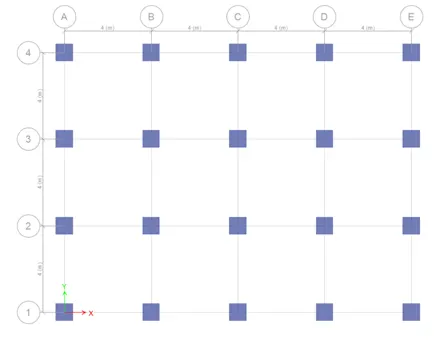
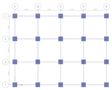
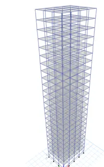
- This is how it will appear after assigning the materials to the grids.
Step-7
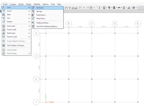
- Now its time to assign the Supports whether fixed or hinge or pined
- In this case hinge support is given that is restricted along x and y only.
- it is done by selecting the points from base plan and assigning the hinge support as shown below.
Step-8
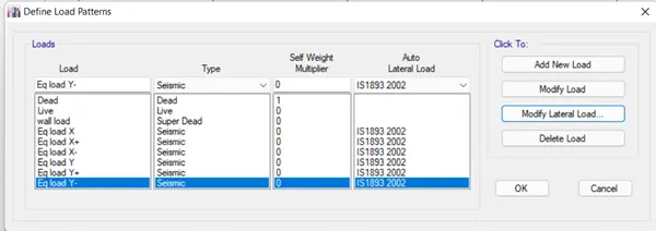
- Defining of loads acting on the building that is
- Dead load, live Load, Wall Load, and Earthquake load.
- For Earthquake load There loads are given those are EQ in X, EQ in X+, EQ in X- and EQ in Y, EQ in Y+ and EQ in Y-
- As shown below.
Step-9
- Now Its time to assign the loads where ever acting
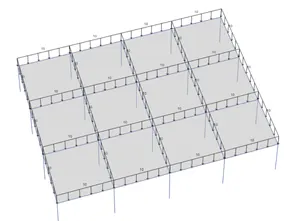
- Select the shell load option and assign the shell load of 3kN/m2 ton each slabs.
- and by selecting distributed load option and giving 10kN/m to all the beams placing between the column as shown below.
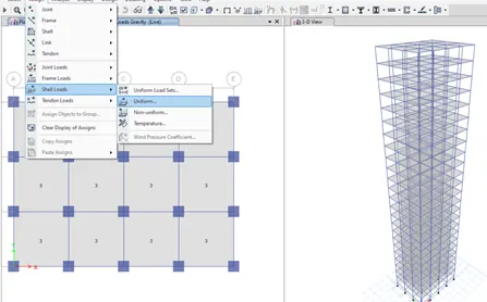
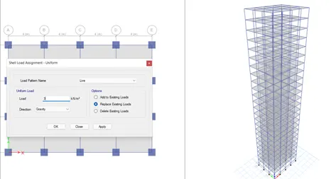
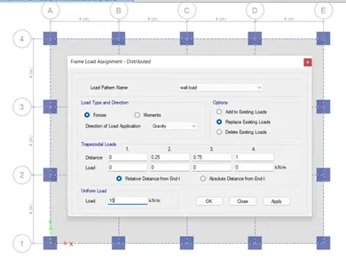
- To Check whwther the loads are propery placed use Perspective Toggle option.
Step-10
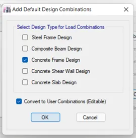
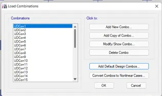
- Now its time to assign the load combinations
- As in etabs Load combination is alreay defined just to select proper load combination
- and press okay to assing as shown below
Step-11
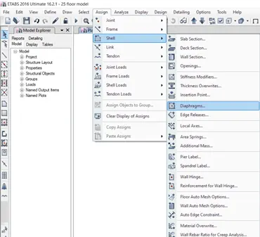
- Now Assign the Diaphagram in the sloabs.
- as it is important to set the center gravity of structure as shown below
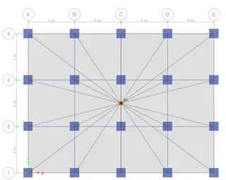
Step-12
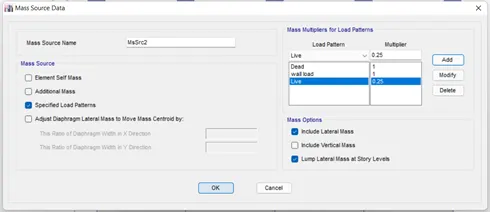
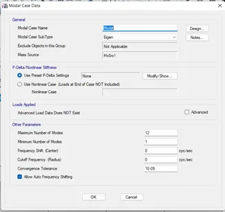
- Now Assign the mass sorce data and modal case data
- so that select the assign option and select modal sorce data
- and along with that select modal case data and assign to the structure.
- As shown below.,
Step-12
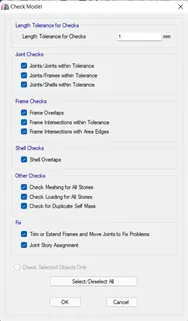
- Now the last step is to annalyze whether the structure is free from errors or not
- So select the analyze option and check all the options as shown
- and wait for the message to display as shown below,
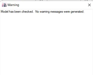
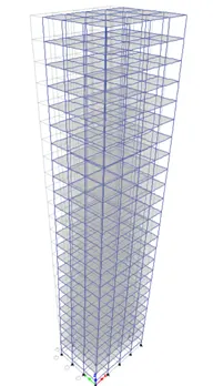
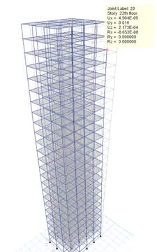
- This completes the modelling of 25 storey building using Etabs
- Now it time to check whether the building is satisfying the clause given by the IS Code 1893 part 1 2016
#2 Check if the translational fundamental natural period of vibration in both the x and y direction is approximately: Tx1= 4.4 second Ty1= 4.2 second
This check will help confirm if modelling is done correctly. Some deviations from the above values is possible (± 2%). But any major deviation will suggest an error in modelling.
Observation:
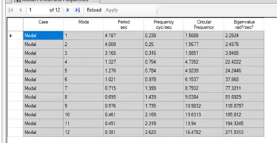
- From the above table the translational fundamental natural period of vibration in both the x and y direction is approximately: Tx1= 4.187 & second Ty1= 4.2 second Respectivelly
- Hence there is a varion grater than 2% hence there is some mistakes in modelling.
#3 Check if the following provision in Table 5 of IS 1893 (part 1) – 2016, on torsional irregularity satisfied:
The natural period corresponding to the torsional mode of oscillation must be less than the two fundamental translational modes of oscillation along each principal plan directions.
Observation:
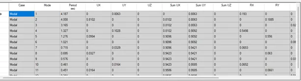
From the above modal participation mass ratio table obtained in etabs it is clearly shown that The natural period corresponding to the torsional mode of oscillation is less than the two fundamental translational modes of oscillation along each principal plan directions. that is 0 <0.8063 along Y and 0.8102 along x Hence this clause is satisfied.
#4 Check if the two provisions of clause 7 in Table 6 (shown below) of IS 1893 (part 1) – 2016, regarding vertical irregularity is satisfied
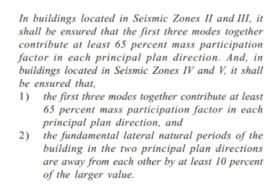
Observation:
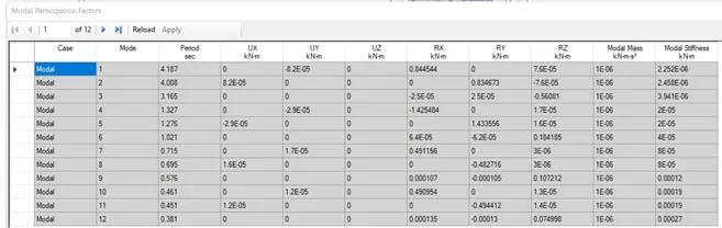
- From the above table the 1st 3 modes that is 4.187+1.327+0.715=6.229 along X Similarly
- 4.008+1.276+0.635=5.919 along y and 3.165+1.021+0.576=4.746 along torsional hence all the values are greater that 65% of total modes hence it is satisfied.
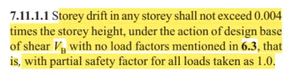
#5 Check if provision on inter-storey drift limitations in clause 7.11.1.1 satisfied. Please note that this check is for Serviceability Limit State and hence is for situation when stucture is subjected to unfactored seismic base shear
Observation:
- From the above table the displacement value is shown
- Hence Storey drift is given by horizontal displacement / storey height
- Therefore along Y =0.8063/3 =0.268 >0.004
- And Hence the Structure is not safe for Eq as it doesnot satisfy the clause.