Modelling of 25 storey building with the specified properties using ETABS
AIM: To model a 25 storey building on ETABS with structural properties as specified below in the condiitons and carry out the followig excercis:
- Check if the translational fundamental natural period of vibration in both the x and y direction is approximately: Tx1Tx1= 4.4 second Ty1Ty1= 4.2 second.
- Check if the following provision in Table 5 of IS 1893 (part 1) – 2016, on torsional irregularity satisfied.
- Check if the two provisions of clause 7 in Table 6 (shown below) of IS 1893 (part 1) – 2016, regarding vertical irregularity is satisfied.
- Check if provision on inter-storey drift limitations in clause 7.11.1.1 satisfied. Please note that this check is for Serviceability Limit State and hence is for situation when stucture is subjected to unfactored seismic base shear
INTRODUCTION:
Extended Three-Dimensional Analysis of Building System(ETABS), it is a sophisticated and suitable special purpose analysis & design program particularly developed for building systems.This software mainly used for structures like high-rise buildings, steel and concrete structures means,the building is subjected to accelerations from earthquake records which represent the expected earthquake at the base of the structure. It gives the structural response through and after the time of application of load.
Here we follow IS 1893:2016 code book for seismic deign.
IS 800:2007 code for steel design.
IS 456:2000 code fro concrete design.
CONDITION:
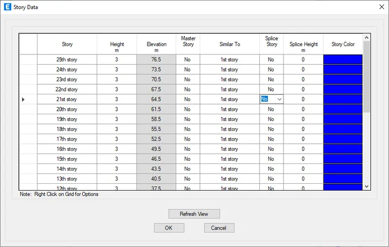
Ground floor or plinth floor level can be taken at a height of 1.5 metres from the base. Each of the successive 25 storeys has a storey height of 3 metres.
Structural Element Sizes
- Beams : 300 × 400 mm
- Columns : 800 × 800 mm
- Slab : 150 mm thick
Material Properties
- Grade of Concrete : M30
- Grade of Steel Reinforcement Bars : Fe 415
Loading
- Dead Load on beams from infill wall : 10 kN/m (Let us assume the same for roof floor in view of parapet)
- Live load on floor : 3 kN/m2 (Let us assume the same for roof floor)
a) Buildings are assumed to be pinned at the base
b) All columns in all storey are of the same size
c) All beams in all storeys are of the same size
d) Building is located on Soil type-II and in Zone-III. Assume other factors if required.
PROCEDURE:
- open ETBAS software and click on new project.
- select user built-in setting option and set to above mentioned codes.
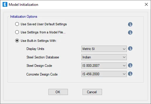
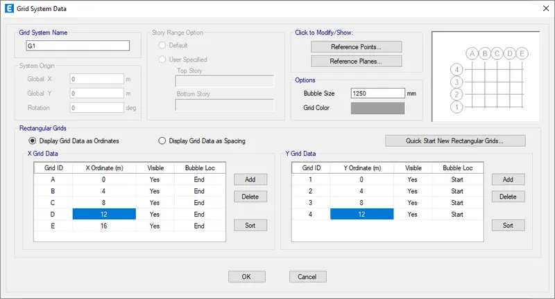
- from new model template,select custom grid spacing on both side and edit the grid pattern as per the condition.
- as well as,custom and edit story data as 25+Gl(1.3m and remaining floors as 3m)
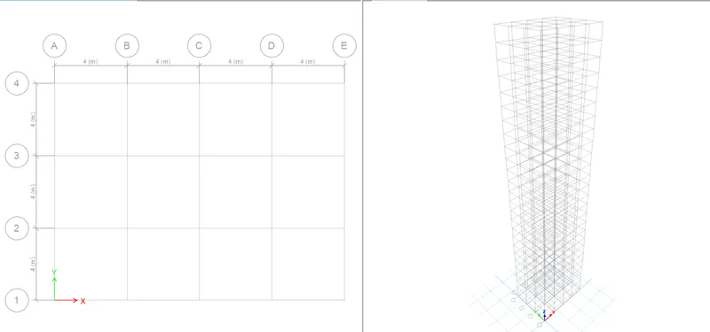
- once grid and story is defined,tab with 3 windows of resultant opens.
- in order to place structural element,need to define the material.
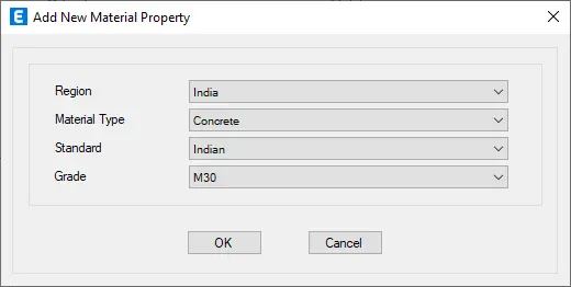
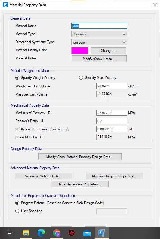
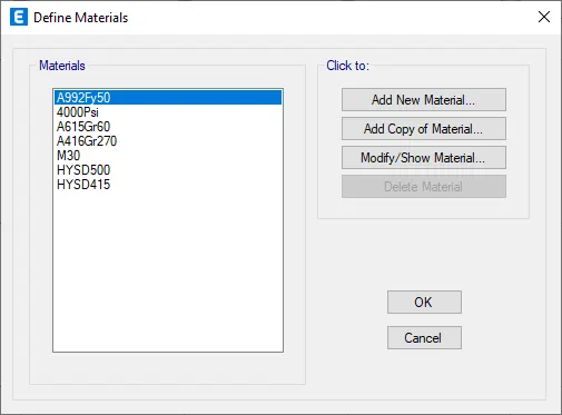
- click on define,select material properties and define for conceret and reinforcement.
- define the column and beam in section properties-frame section.
- click on add property and select rectangular section,define for 300x400 beam.
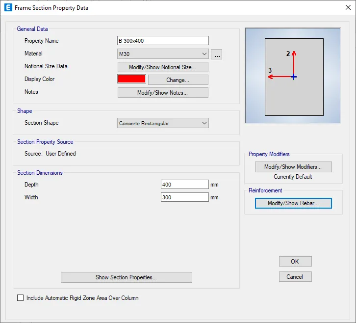
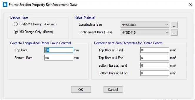
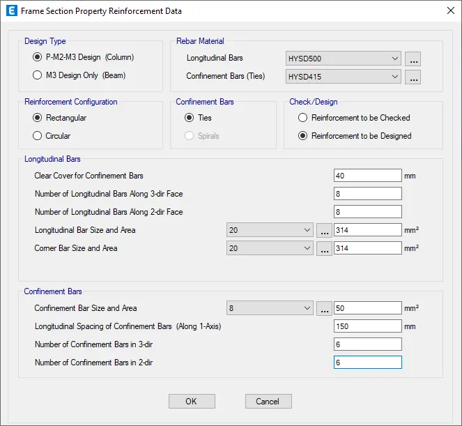
- similalry define for 800x800 column.
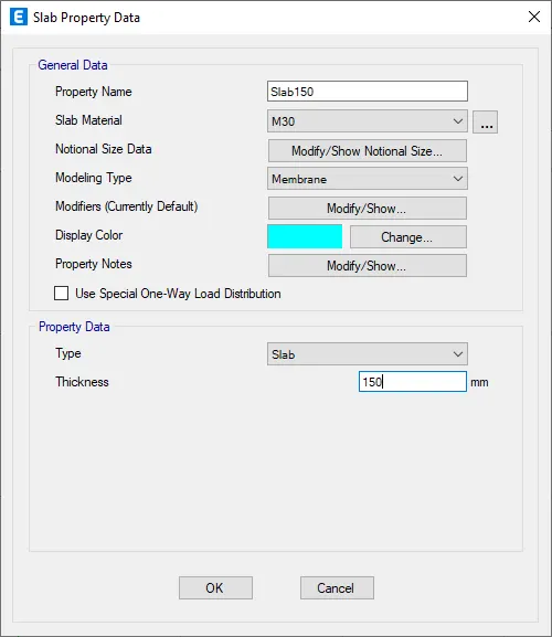
- similarly define slab property.
- set any floor plan and select all stories for column and beam drawing.
- select quick column draw toolbar and place column at grids.
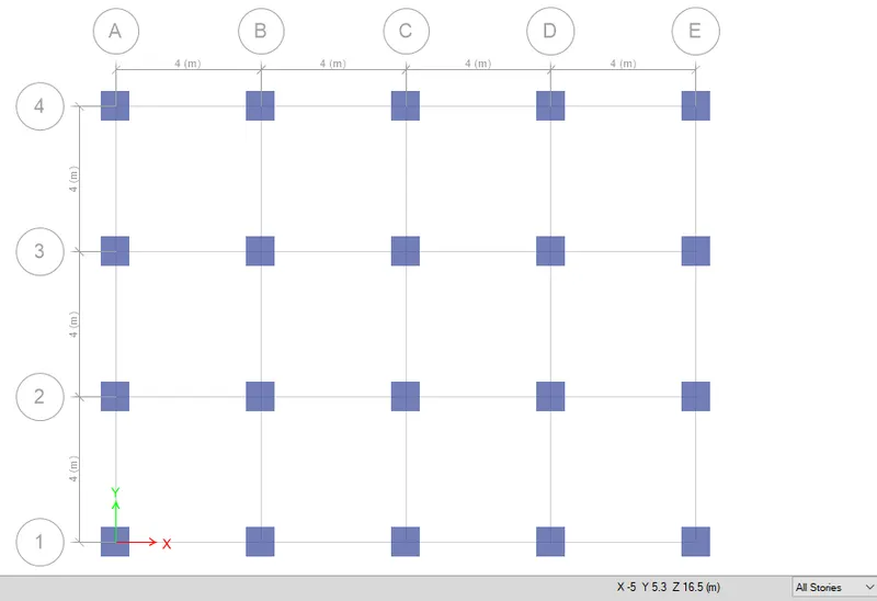
- similarly quick beam/column toolbar as beam is same throughout the structure.
- select quick draw rectangular floor toolbar and set to similar floors,draw the slabs.
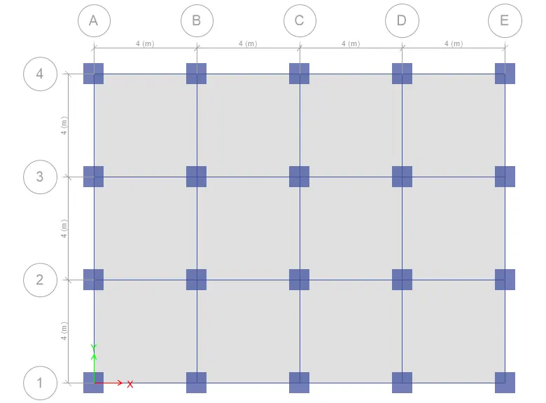
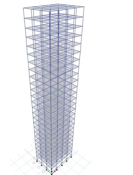
- once structural elements are drawn,set the base condition.
- select base plan-set to one story-select all,go to assign and select restraints from joint option.
- set the base as pinned.
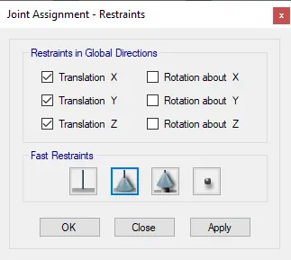
- next step is to to define the loads for dead,live and seismic.
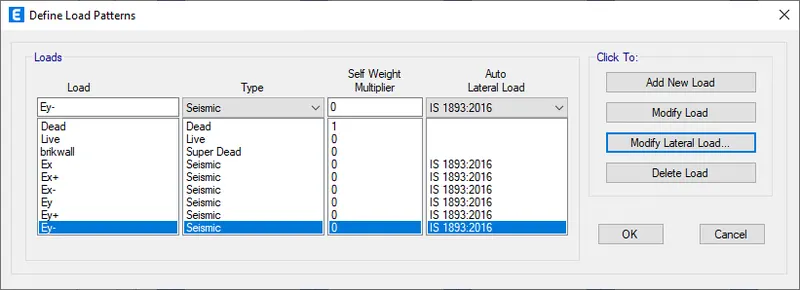
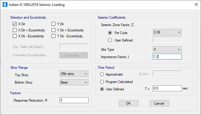
- for sesimic load,keep importance factor as 1.2,time period as 0.5 and soil type II with Z factor 0.36.
- as dead load will be predefined by etabs itself,assign live load and brickwall load to overall strcuture.
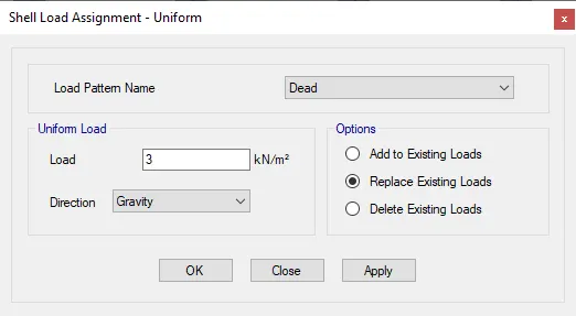
- select all select using select toolbar command,go to assign-select shell load with unifrom pattern and assign live load as 3kN/m2.
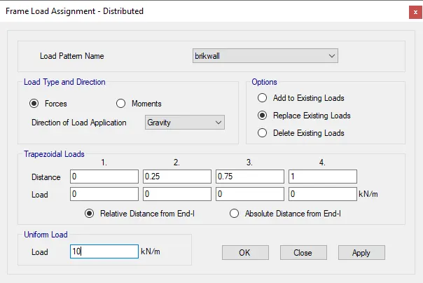
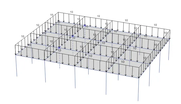
- similarly assign brickwall of load 10kN/m2 by selecting all beams.
- in order to assign earthquake load,define the mass source.
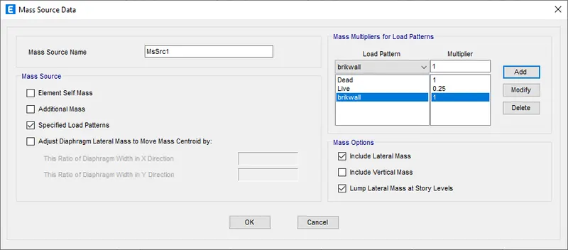
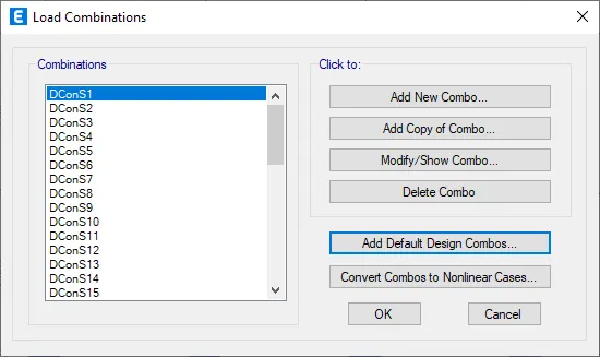
- add load combination,selecting add default and concrete frame.
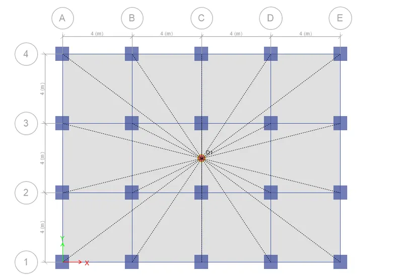
- assign diaphragm by selecting all floors-assign-shell-diaphragm and select D1.
- go to analyze and check model.

- Run analysis-from analyze toolbar.
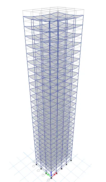
RESULT:
- For given column and beam condition,a 25 story building is modeled and loads are assigned.
- Run analysis is done,with no overlappring of structural elements.
- go to display>show tables>structural output>modal output>modal participating mass ratios.
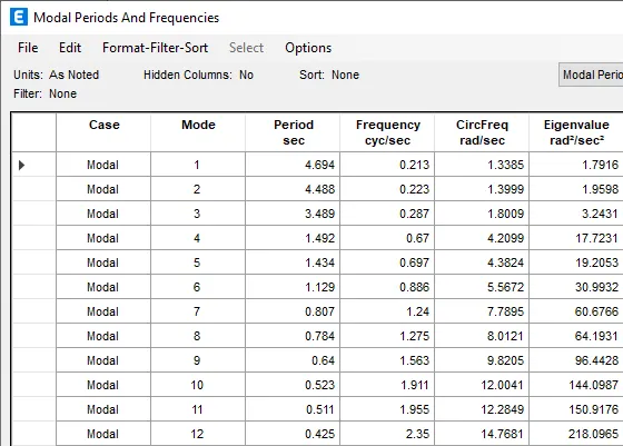
- from the table above,the translational fundamental natural period of vibration in both the x and y direction is approximately are Tx1=4.6 sec and Ty1-4.4sec.Hence modelling is done correctly.
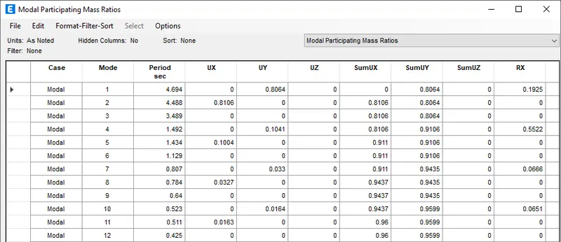
- from above table tx1=4.6 ,ty1=4.4 and txy1=3.4,so the natural period corresponding to the torsional mode of oscillation is less than the two fundamental translational modes of oscillation along each principal plan directions.So torrsional irregularity as per Table 5 of IS 1893 (part 1) – 2016 is satisfied.
- when we add first three modes mass ratio we get more than 0.9,means the first three modes together contribute 65% the mass ratio of whole building.
- But the fundamental natural period of building in the two principal plan direction are away from each other by less than 0.5%.Therefore, the 2nd provisions of clause 7 in Table 6 of IS 1893 (part 1) – 2016, regarding vertical irregularity is not satisfied.
- go to display>story response plot.
- set the display type as maximum story drift and load as Ey.
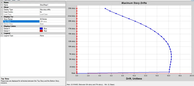
- the maximum storey drift for Ex was found to be 0.016 under the action of design base shear with load factors.storey drift has exceeded 0.004,structure may undergo defromation when subjected to earthquake loads.