Modelling of 25 storey building with the specified properties using ETABS
Aim:
To Model and Analyze a 25 Multi-Story Building using ETABS and checking those results with respect to the IS 1893-2016 Part-1.
Introduction:
- The Seismic Design for the Building or Structures is given by IS 1893-2016.
- We can select the basis for design in the ETABS software while anayzing the structure.
- We can cross-check the results after the analysis performed on the structure with the specification provided in the IS code 1893-2016.
Procedure:
- Grid Creation:
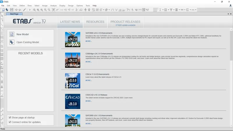
- Open and create a New project in ETABS.
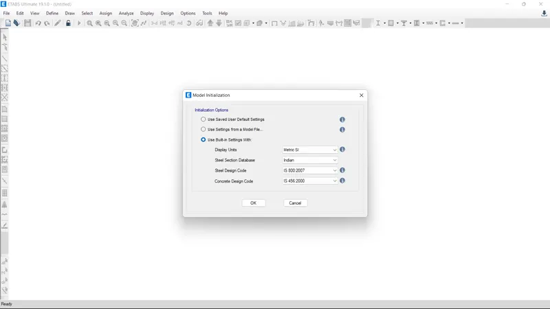
- Give the code and units which needed to be followed.
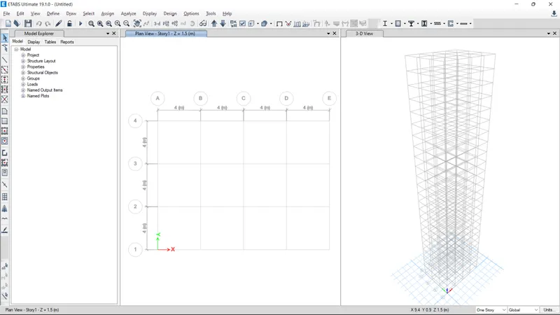
- Create the Grid spacing either custom or inbuilt Grid spacing by giving the number of grids in X and Y direction.
- Now enter the storey heights using custom option.
- Rename the storey names as per the requirement.
- Assign the Master storey for the required storey or floors for easy modelling and load assigning.
- After creating the grids and storey definitions a skeleton structure is developed both Plan and 3D view.
- Modelling:
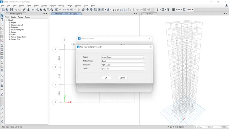
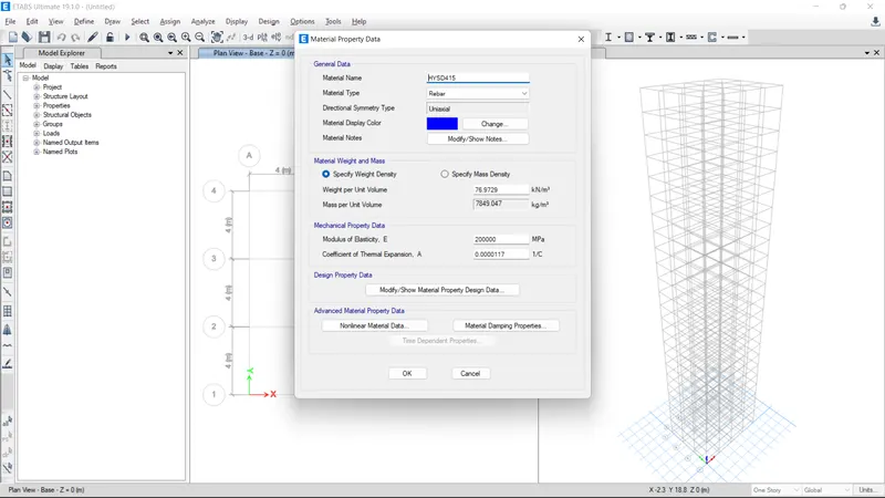
- We need to create the Material Properties.
- For concrete create M30 and for Steel reinforcement create Fe-415.
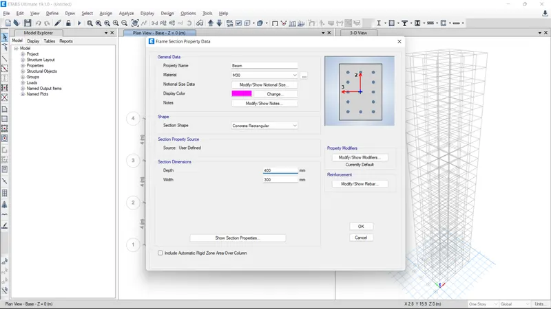
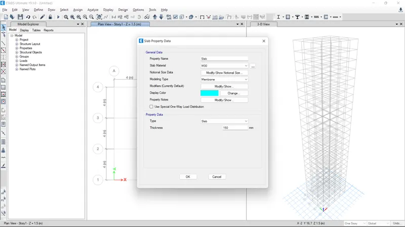
- Now we need to create the Section Properties for Beams, Columns and Slabs.
- Go to Define Tab > Section Properties > Frame Sections > Add new property > Select the material from the material property already created.
- Add the reinforcement details for the Column and Beams respectively.
- The same procedure is followed for the Columns also.
- For Slab - Select the Model Property as Membrane because we dont want the slab element to act as a Flange section by taking the Shear Force.
- After creating the Sections we need to model them into the structure.
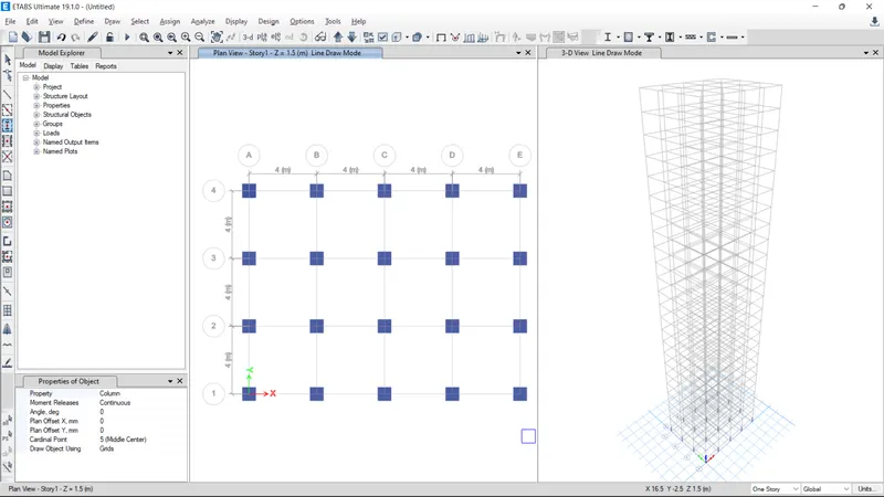
- Select Quick Draw Column option and provide columns at every grid intersection.
- Check whether the option is selected to all floors.
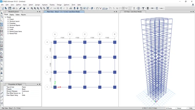
- Now comes the Beam modelling, click on Quick Draw Beam and select All floors option.
- Select the required data type and select the grid lines where we need to model the beam.
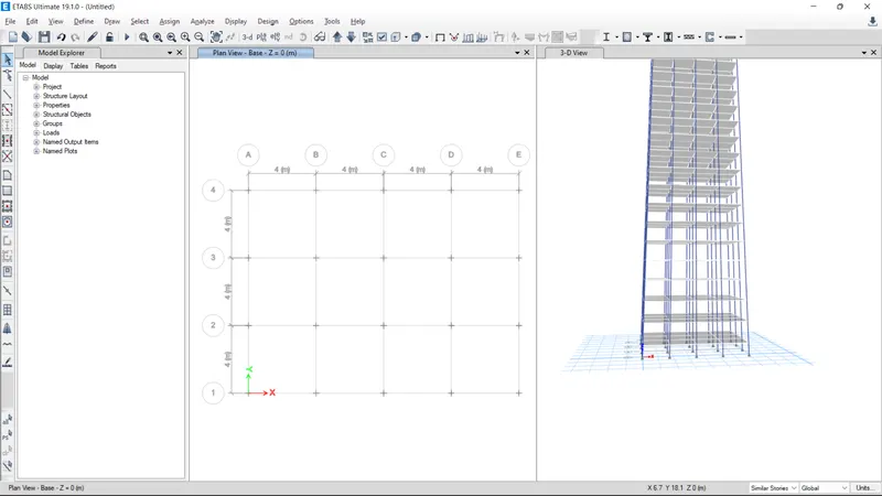
- Now for slabs we do not want to model it in Plinth.
- Therefore go the First storey and select similar storey option.
- Model the slabs as per the requirement by selecting Quick Draw Slab.
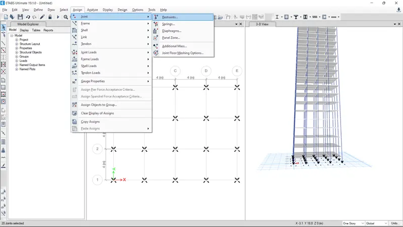
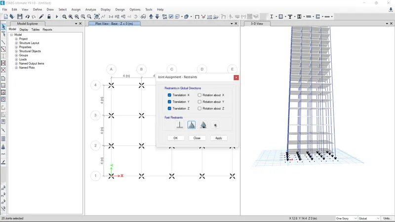
- Now for assigning the supports go the Base floor and select the grid points.
- Go to Assign > Joints > Restrain > Se;ect the required support condition.
- Assigning the Loads:
- Go the Define > Load Patterns.
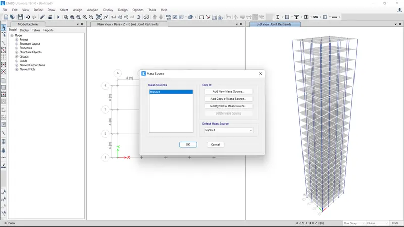
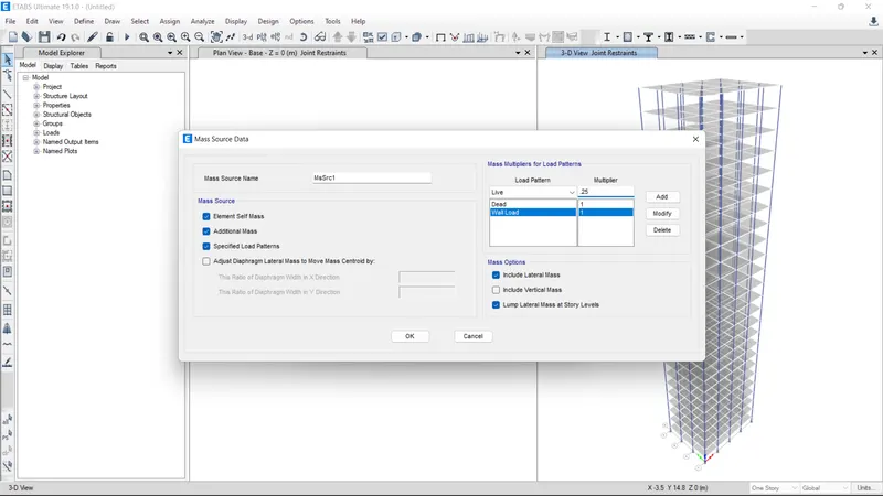
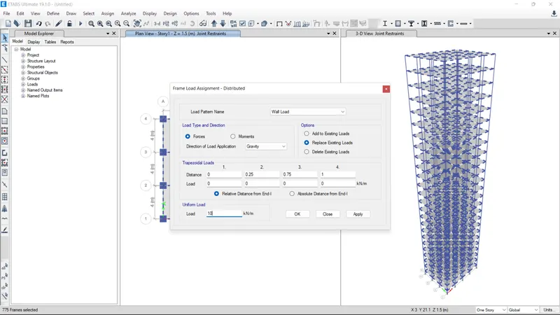
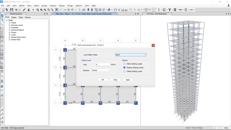
- We need to add new load properties such as Seismic, Live and Wall loads.
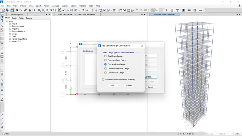
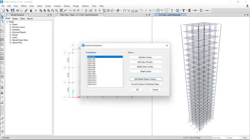
- Give the load combinations to the loads assigned.
- Analysis Commands:
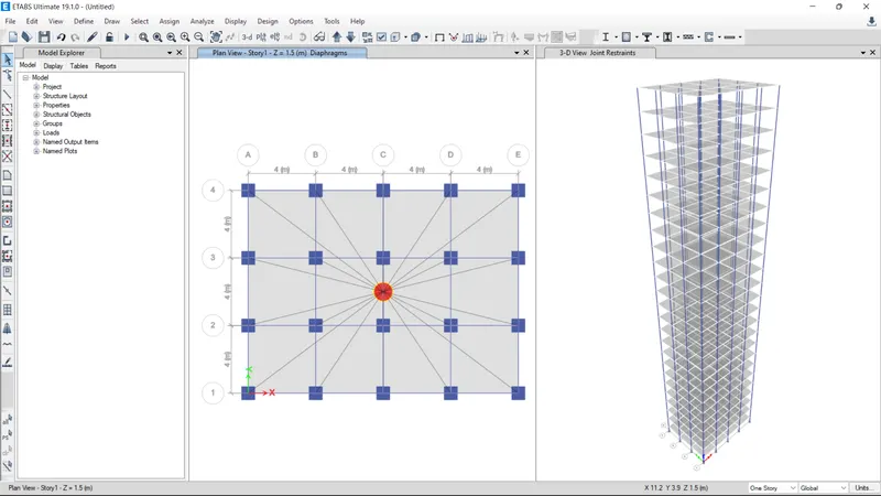
- For the Seismic Analysis we need to assign the Diaphragm command.
- Select all the Slabs > Assign > Shell > Diaphragm > Apply.
- A Centre of Mass is created.
- Now firstly check the model for any overlapping or errors.
- Now run analysis.
- Checking the Results:
- After the Analysis is completed.
- Go to the Model Explorer > Tables > Analysis Results > Model Information.
- We need to check the Modal Time Period and Modal Participation Factor.
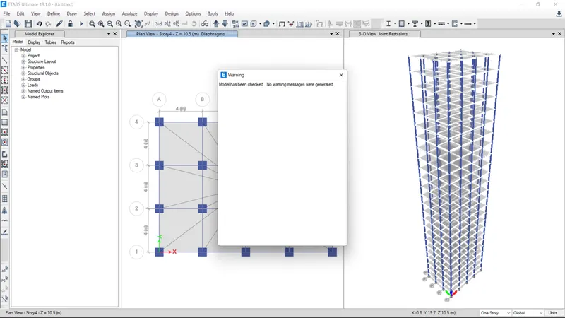
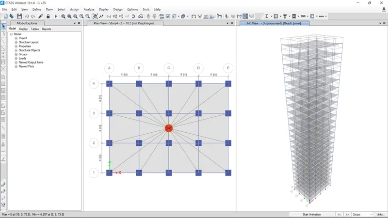
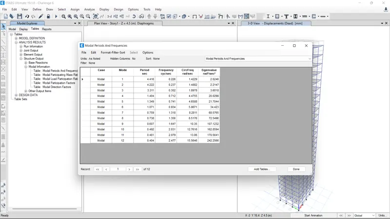
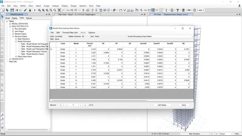
Result:
The structure has been Modeled and Analysed and the required results are displayed below.
|
Criteria |
Desirable Solution |
Exercise Result |
|
|
Fundamental Translational Natural Period |
X-Direction |
4.4 sec |
4.41 |
|
Y-Direction |
4.2 sec |
4.22 |
|
|
Torsional Irregularity |
IS 1893-2016 (Part-I) Table-5 |
Torsional Mode Time Period should be lesser than X and Y direction Time periods |
Yes |
|
Vertical Irregularityk |
IS 1893-2016 (Part-I) Table-6 Clause-7 |
First Three modes together should contribute at least 65% in mass participation factor in each principal direction |
Yes |
|
Fundamental Lateral natural periods in two principal plane directions are away from each other by at least 10% |
No |
||
|
Inter-Storey Drift |
IS 1893-2016 (Part-I) Clause 7.11.1.1 |
Storey Drift shall not exceed 0.004 times the storey height for base shear with no load Factors |
Yes |