Modelling of 25 storey building with the specified properties using ETABS
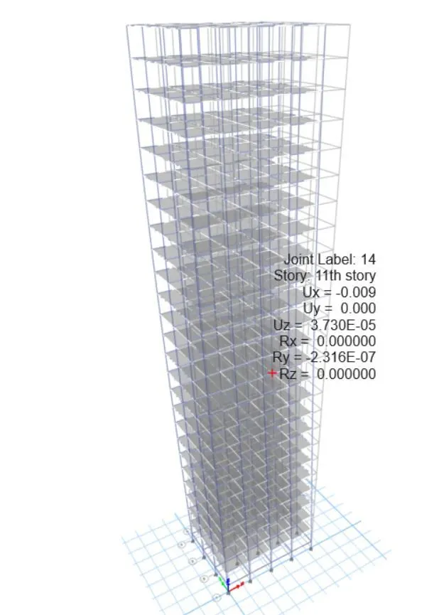
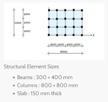
1. Model a 25 story height building on ETABS with structural properties as specified below. Ground floor or plinth floor level cab be taken at a height of 1.5 meters from the base. Each of the successive 25 storys has a story height of 3 meters.
ANSWER
Step 1
- OPEN on ETABS Application.
- Click file, select the option of NEW model and click it.
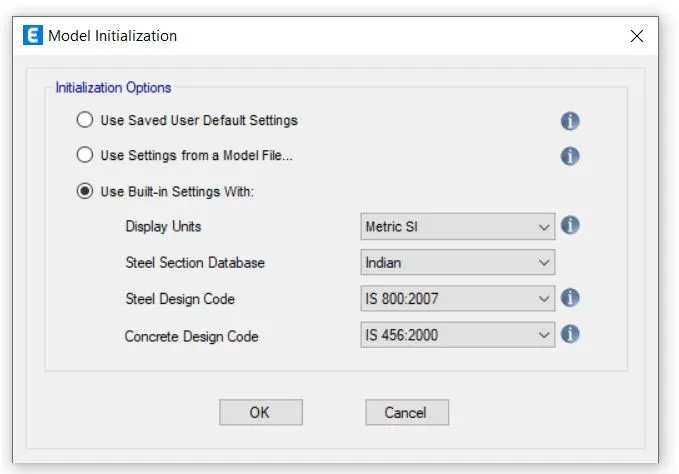
- After choosing the new model, automatically the dialog will arrive that is called model initialization.
- Next, we choose Built-in setting, as there type the data and unit of our structural plan.
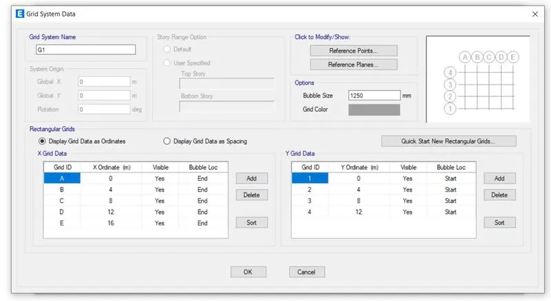
- Choose Custom Grid setting, to set the grid by custom at a given dimension of X & Y direction.
- Here we can see about a Grid data an spacing & Grid spacing an ordinates by choose our convenient.
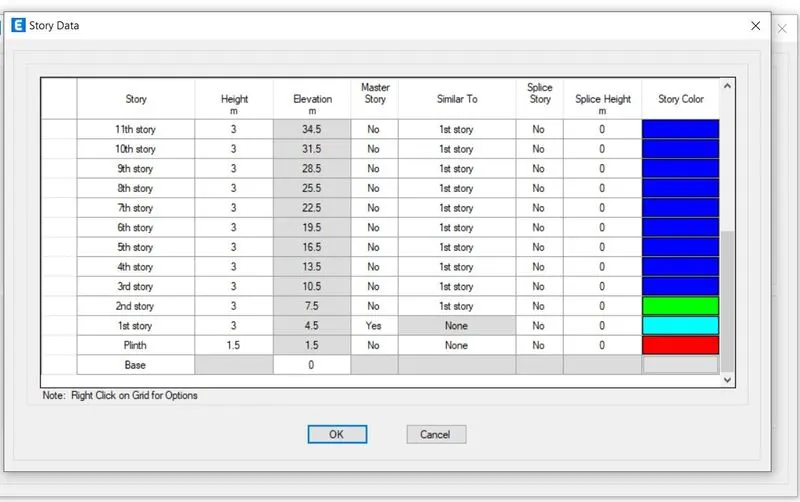
- As well as should add the CUSTOM story Data for plinth to 1st story height is 1.5m and other all 25 story height is 3 m.
- To consider the 1st story is master story.
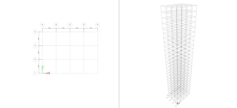
- Then, click ok we get the model frame structure in windows.
Step 2
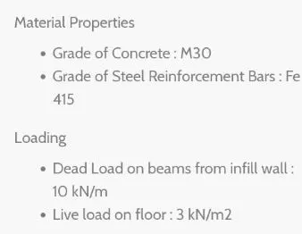
- Add the material properties of concrete & rebar.
- Choose DEFINE tool > material properties > add materials.
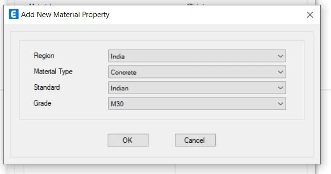
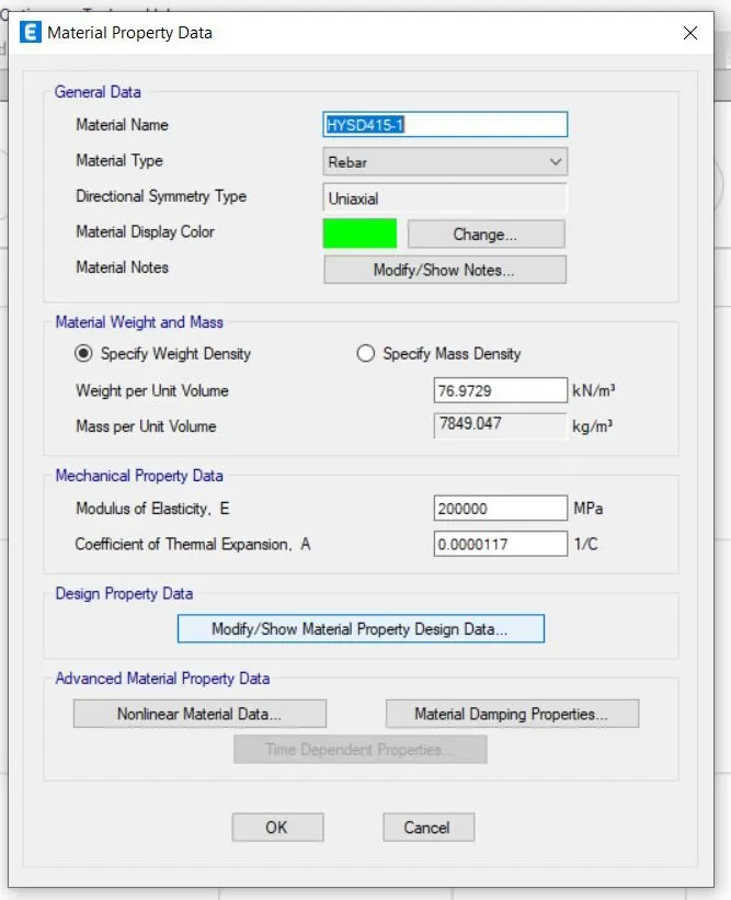
- The Same we add the material properties of beam & column.
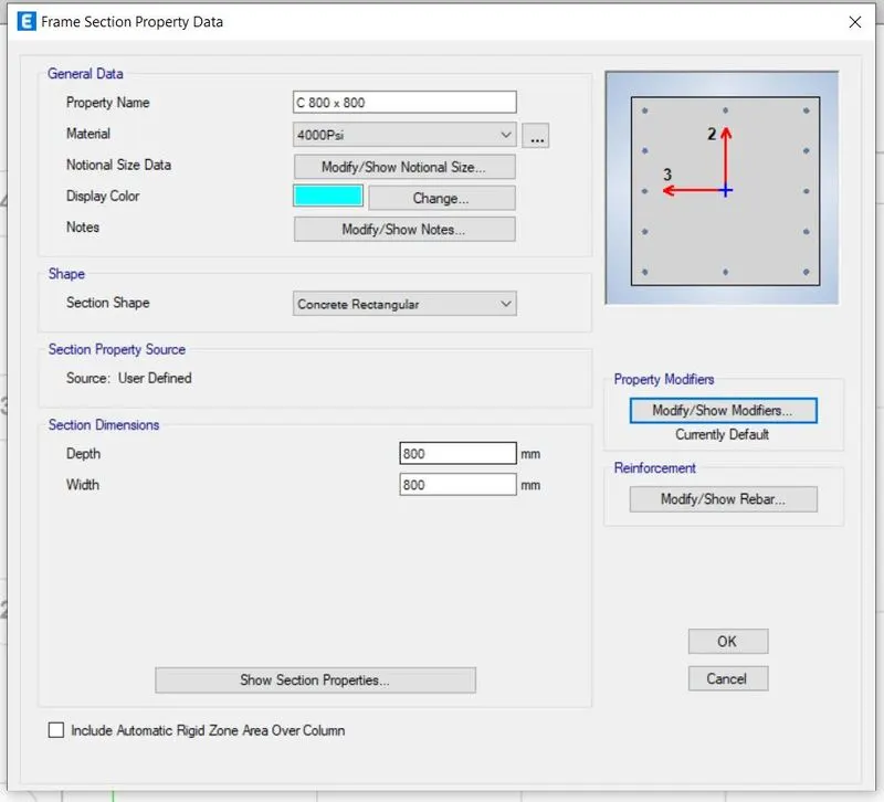
- Choose DEFINE > section properties > frames section.
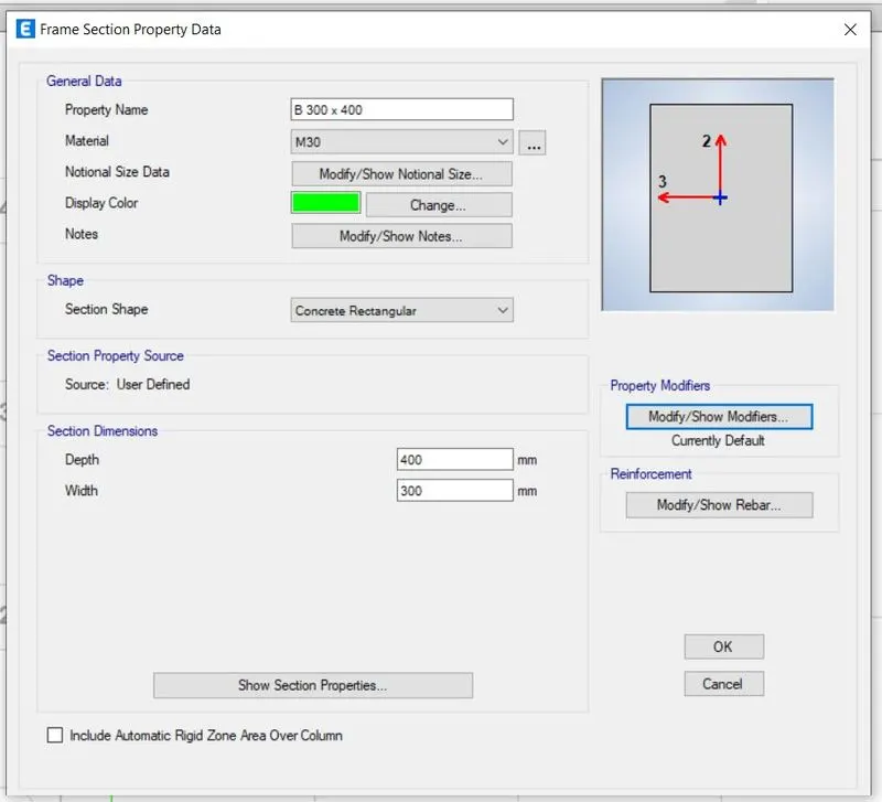
- The beam size is 300mm x 400mm.
- The column size is 800mm x 800mm.
- As we can modify the reinforcement details and rebar materials and also should provide the clear cover of both the section.
- To check and modify the properties in section.
- For here, we have to take the reference from IS 1893:2016 For structural analysis, moment of inertia.
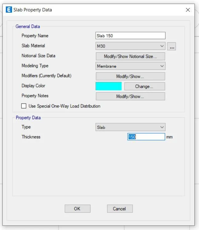
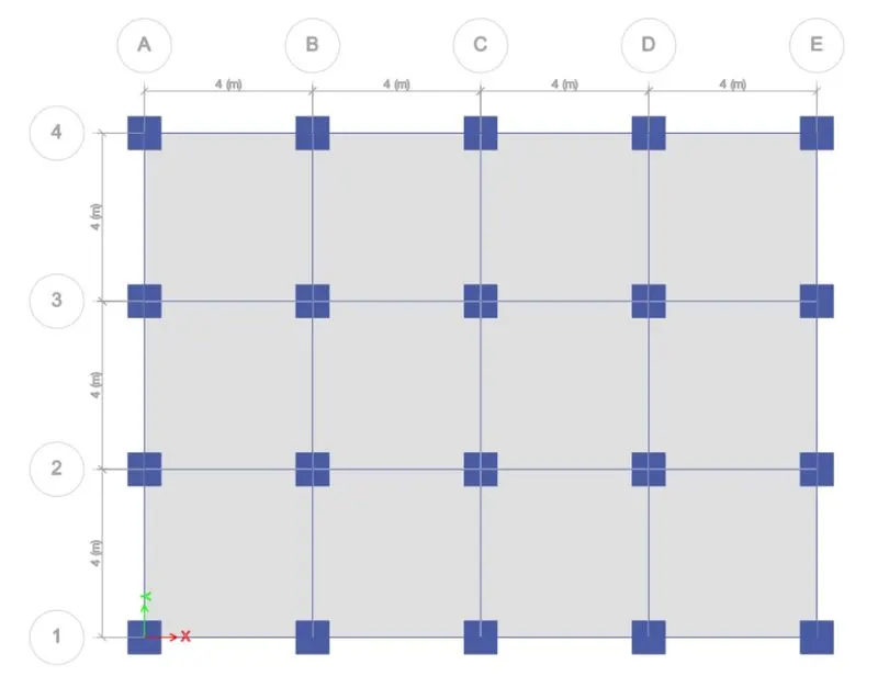
- To add the slab at thickness of 150mm.
- Choose DEFINE > section properties > slab section.
Step 3
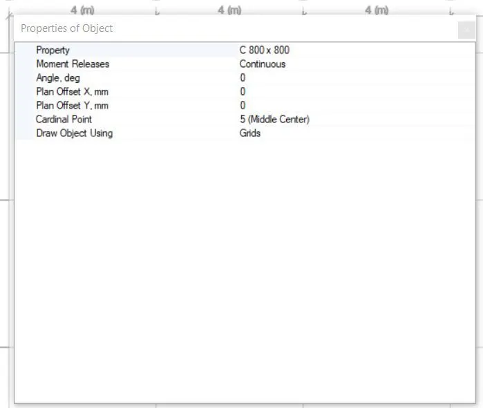
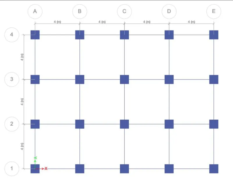
- To add the column on structure by selecting the quick draw column(3D plan).
- Before we select the column details Of C 800mm x 800mm.
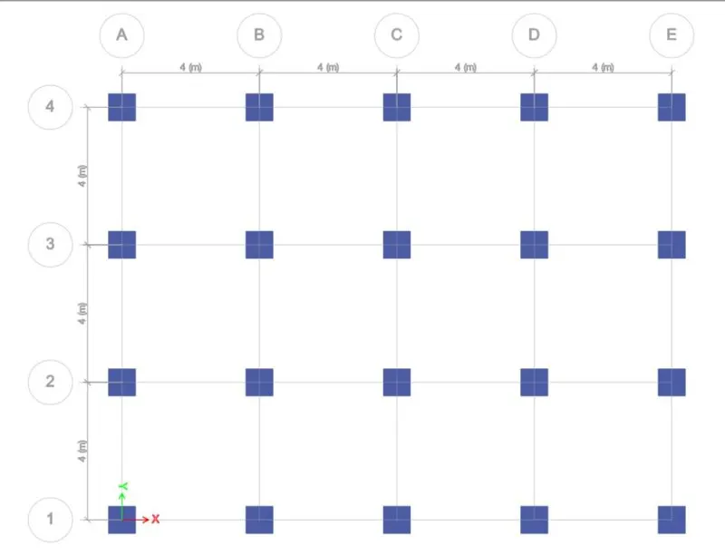
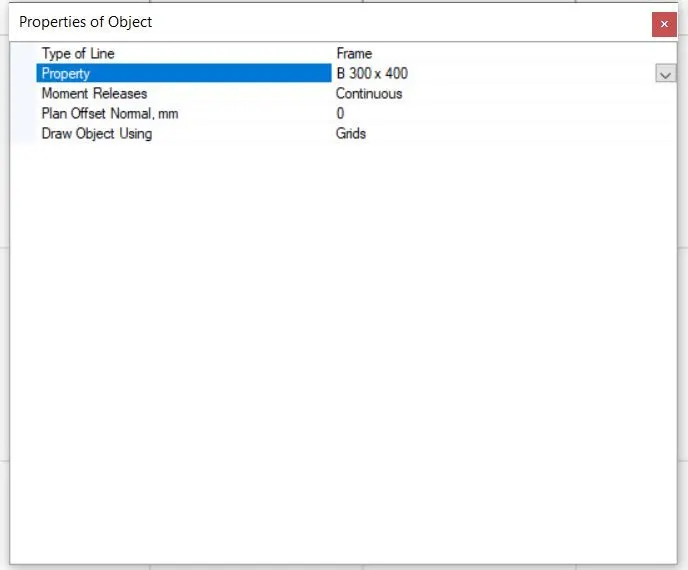
- The same we add the beam by selecting the beam draw tool at the selection of all beam grids.
- To select the beam size is B 300mm x 400mm.
- Similarly, we can add the slab to choose from 1st story as similar to all other 24 story with the thickness of 150mm.
Step 4
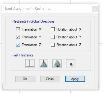
- To add the joint details at the base story at foundation functions.
- Choose ASSIGN > joints > Restraints.
- Here we select Pinned joints at the base level.
Step 5
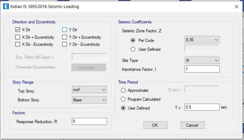
- To set the appropriate load values and properties about a structure.
- Choose DEFINE > Load patterns > Add loads.
- For loads are live, dead, brick wall, earthquake in X & Y direction.
Step 6
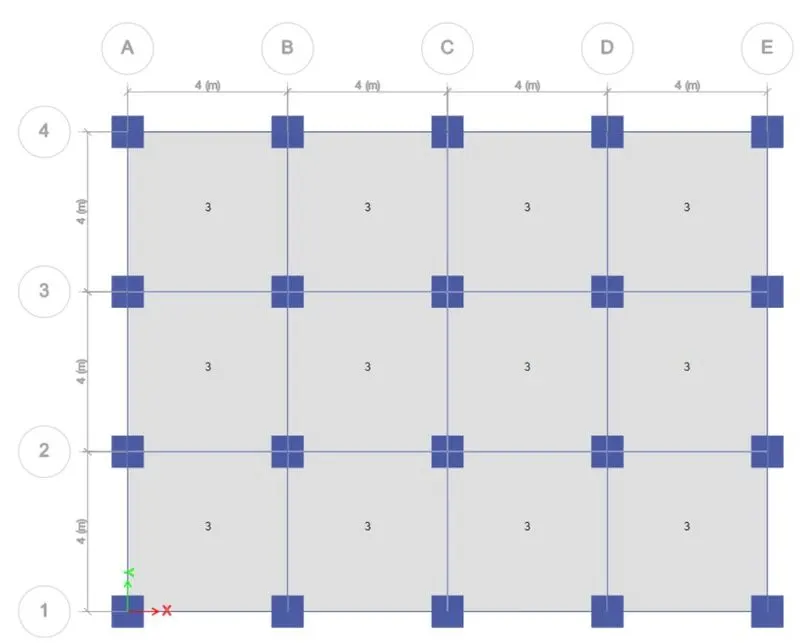
- To assign the live loads in a floors as we add the given data of 3 kn/m^2.
- Choose EDIT > edit stories from templates > modify data.
- Choose ASSIGN > shell loads > Uniforms.
- The values of live load id 3 kn/m^2.
- It can similar to all other stories by we selecting option under similar.
Step 6
- Simultaneously we add same procedure of adding the dead load.
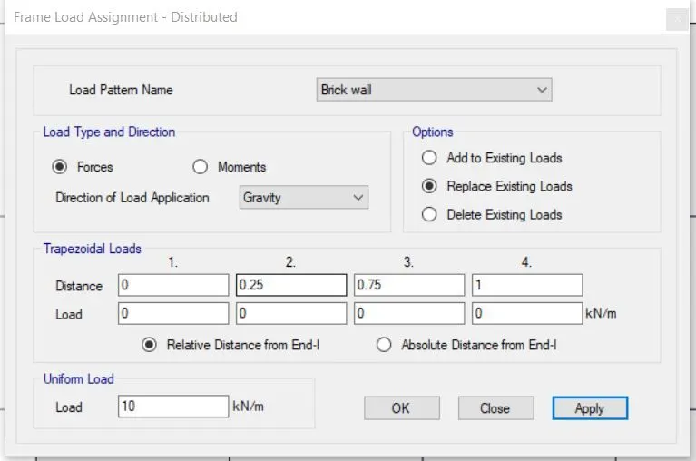
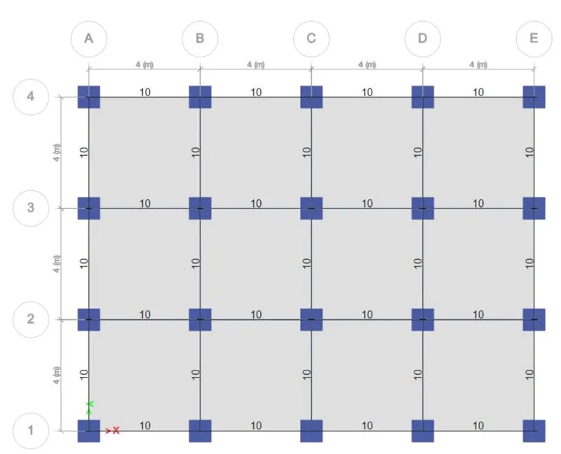
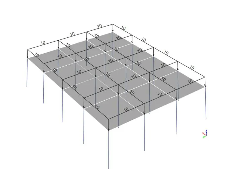
- Choose ASSIGN > frame loads > Distributed loads.
- The dead of brick wall infill is 10 kN/m.
Step 7
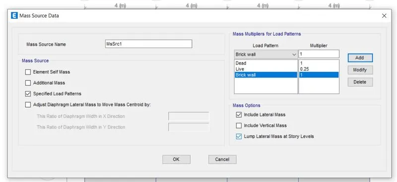
- To add data about mass of seismic properties.
- Choose DEFINE > mass source > modify show mass source.
- As we define the data of dead load, brickwall infills ad 25% of live loads.
Step 8
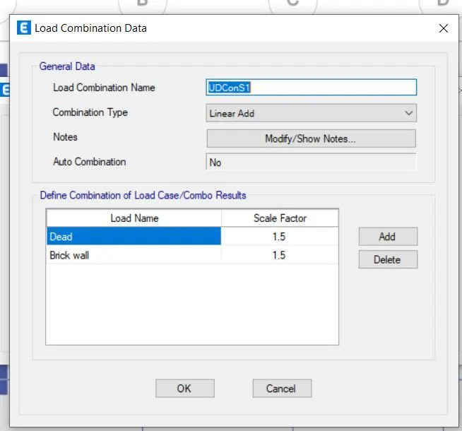
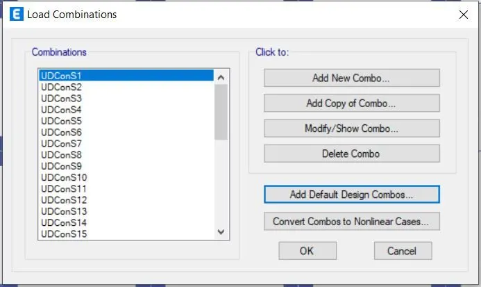
- Here automatically analyze the load combination about whole structure.
- Choose DEFINE > load combination > Add default design combination.
Step 9
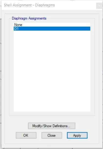
- To applied the diaphragms.
- Choose SELECT > object type > floor ( slab).
- Choose ASSIGN > shell > Diaphragm .
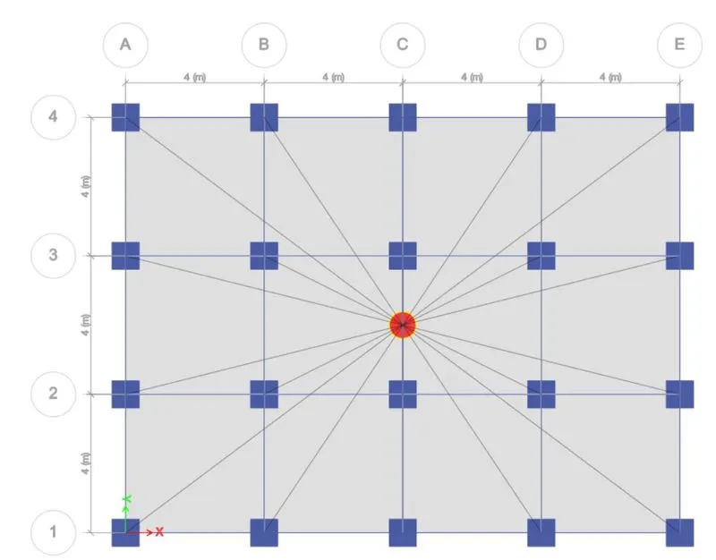
Step 10
- To analyze the structure.
- Choose ANALYZE > check model .
- Then, click ok.
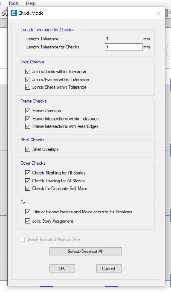

Step 11
- We analyze the whole structure of checking the deformation patterns in frame.
- As well as we can see visualize the effect of structure deformation.
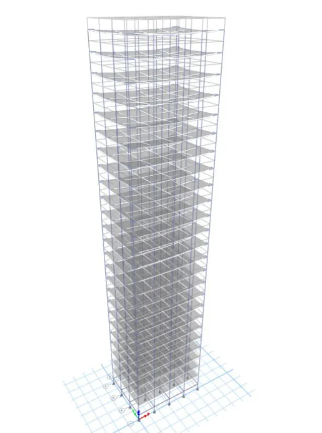
Step 12
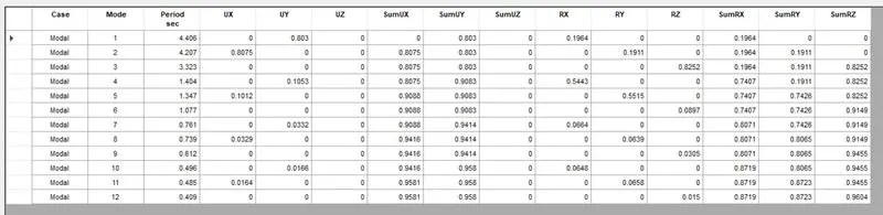
- Finally, we find out the model response under 12 modal shapes.
- Choose DISPLAY > show table >analysis > structure output > modal information > table –modal participant mass ratios.
- We get the time period about all modal shapes under seismic forces.