Modelling of 25 storey building with the specified properties using ETABS
Aim: To model 25 storey structure as shonw in the challenge description and analyse the structure when subjected to described load.
Introduction: On ETABS, 25 storey structure will be modelled as shown in fig A, have column size of 800x800m, beam size of 300x400mm slab thickness of 150mm. Further this structure will be analyzed by applying dead load on beams from infill wall: 10kN/m and Live load on floor: 3Kn/m2 and finally check on the model will be conducted as per the code so that to understand whether the model was structured in proper manner.
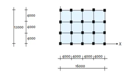
Fig A: Building structural plan.
procedure:
Step 01: To structure a model
- Open Etabs and click on New model as shown in Fig B.
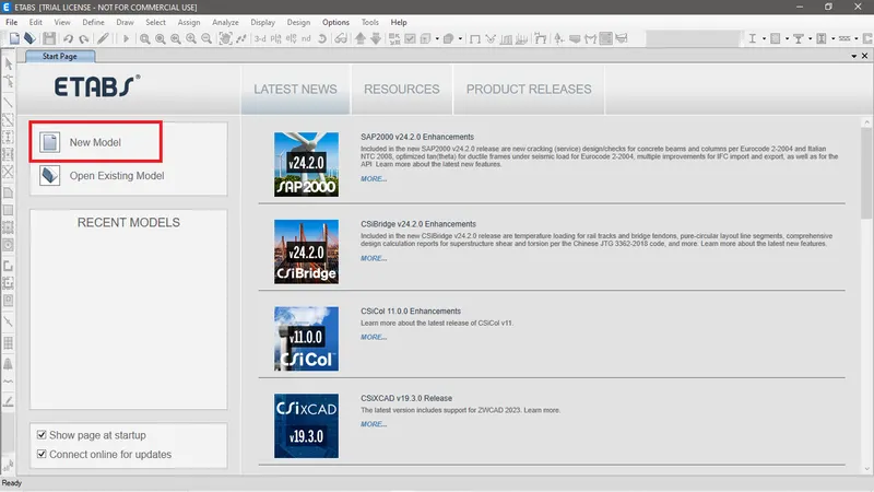
Fig B: New model creation
- Now select Use built in select with and define each option as per your country code and then click on OK. as shown in Fig C.
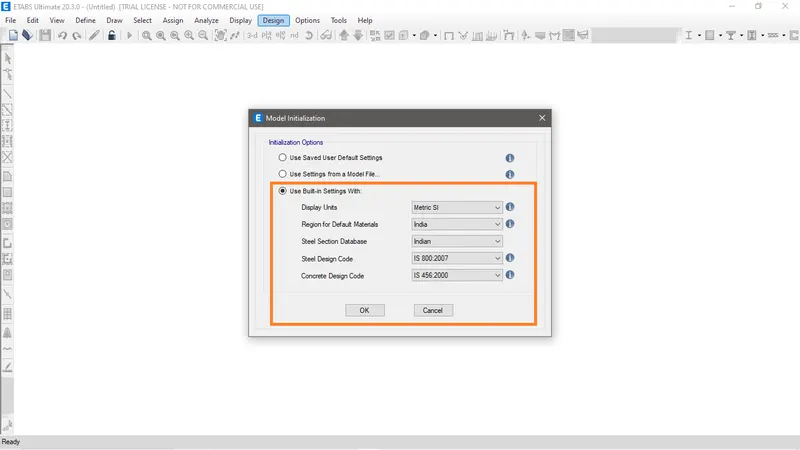
Fig C: Defining standard codes to be used for designing.
- Now select custom grid spacing and click on edit grid data as shown in fig D.
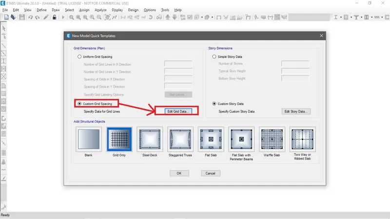
Fig D: Customise grid data.
- Now define the grids space and add grids as per required in both X and Y directions as shown in Fig E.
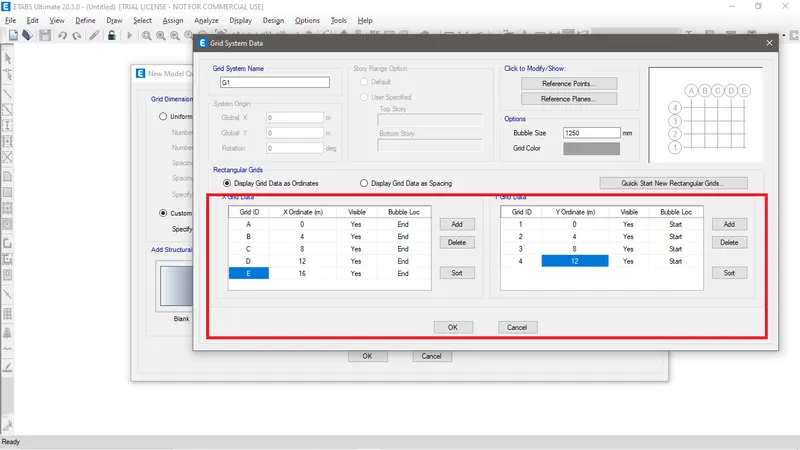
Fig E: Defining grid space in both X and Y directions.
- Now click on Edit story data as shown in fig F.
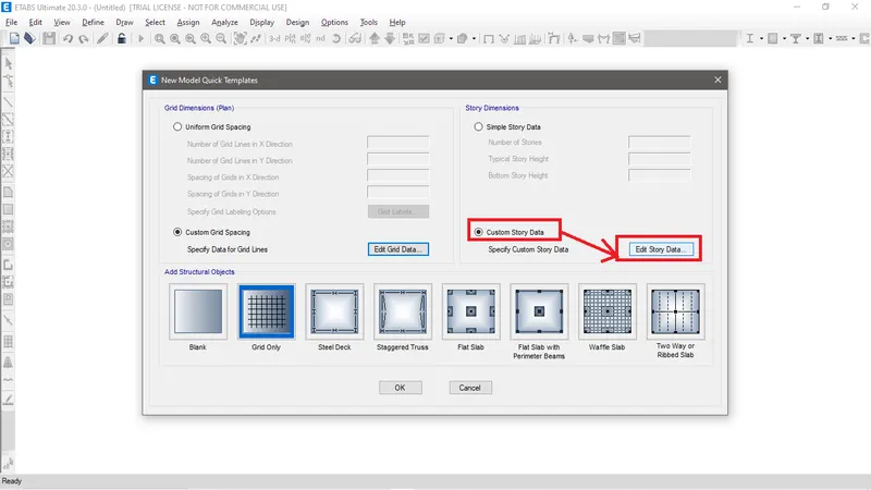
Fig F: Customise story data.
- Now define the each story height and if all the story is identical to 1st story except Plinth level then select 1st story as master story and define all the other story similar to 1st story as shown in fig G.
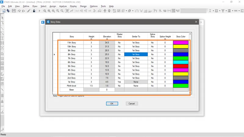
Fig G: Defining story.
- To add another story above right click on the story> Add story > Keep existing story heights as shown in fig H.
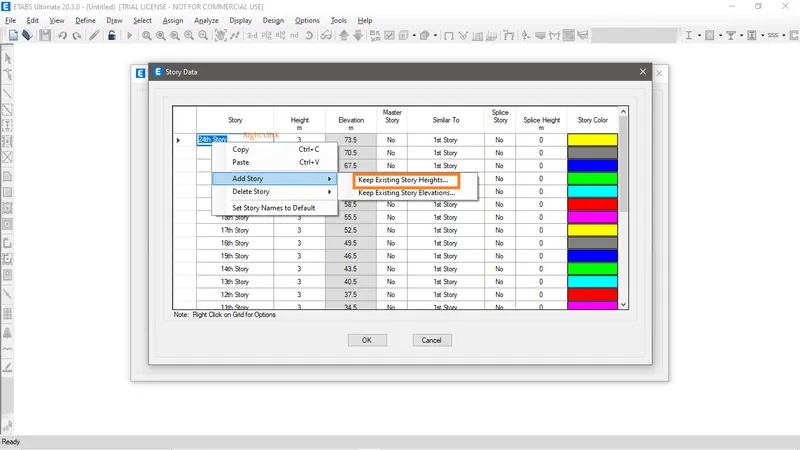
Fig H: Story addition.
- Now set the sotry height and above what the story to be set as shown in fig I.
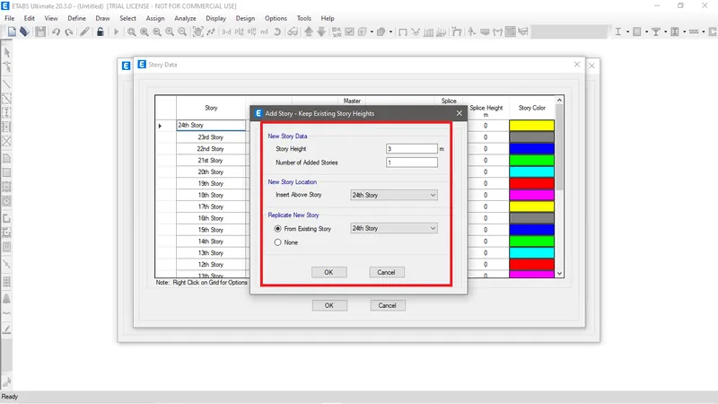
Fig I: Setting up new story.
- In Fig J we can see new story added and defined too.
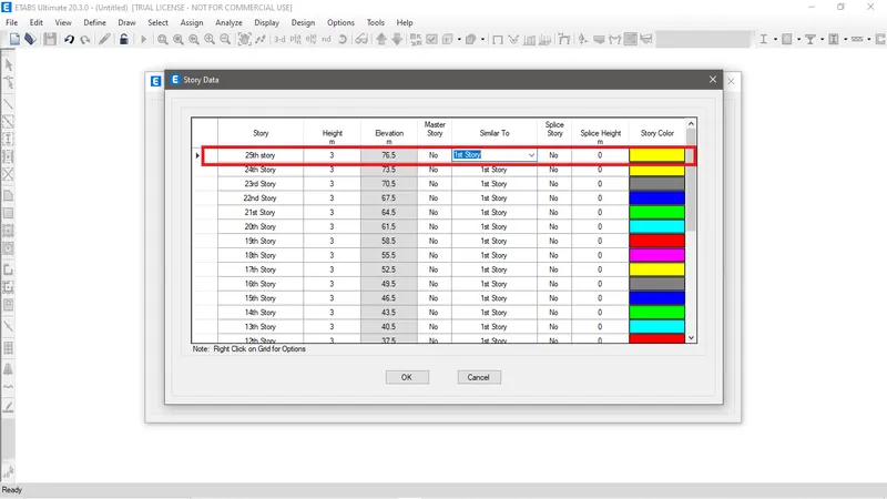
Fig J: New story added.
- After clicking Ok we can see in Fig K that the grid line is modelled in plan view and 3d view by default.
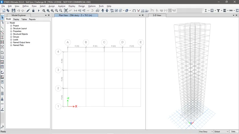
Fig K: Plan view and 3d view of grid line.
- The grid line of the structure is created, moving ahead to assign column, beam and slab material to the structure. First let's define concrete material property and to do that, go to Define tab in ETABS > Material properties as shown in Fig L.
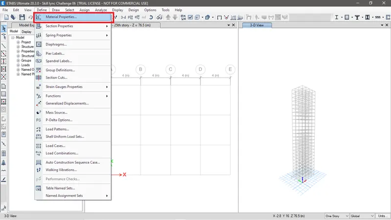
Fig L: Material properties.
- Click on to Add new material property as shown in fig M.
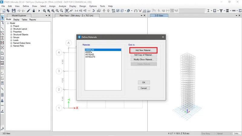
Fig M: Add new material.
- Now select the Region, Material type, Standard and grade as required and then click on Ok, as shown in fig N.
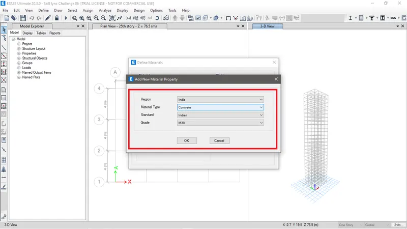
Fig N: Defining concrete material
- Now the computed data of the material will be displayed where no changes to be made. Now click on OK again as shown in fig O.
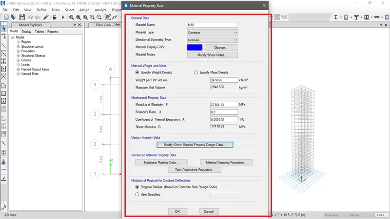
Fig O: Material property data.
- We can see in Fig P that the Concrete material is added.
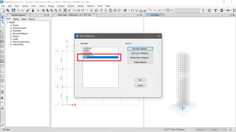
Fig P: Concrete material added to material property.
- Similarly to add define steel material go to Add New Material again and then select Material type as rebar and grade as required, Here the grade is taken as Fe 415 as shown in f Fig Q.
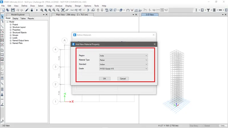
Fig Q: Defining rebar property.
- Now computed data of rebar property is displayed as shown in fig R. Going ahead without any changes just on a click OK.
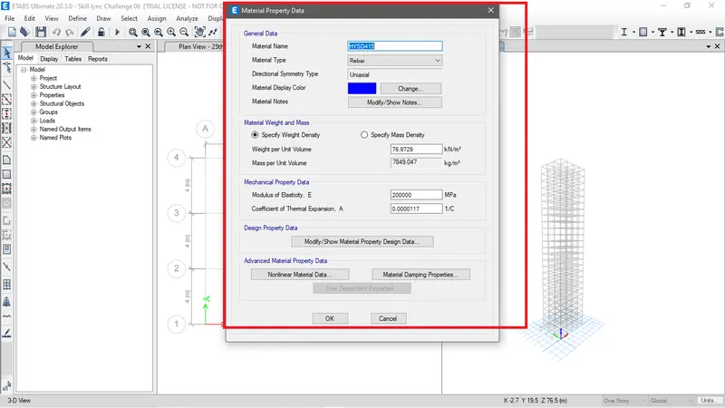
Fig R: Material property data of rebar.
- Rebar property is now added to material property as shown in fig S.
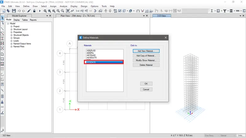
Fig S: Rebar property added.
- Moving ahead defining frame section that is column and beam. To define beam of dimension 300x400 mm. Go to Define tab > Section properties > Frame section as shown in fig T.
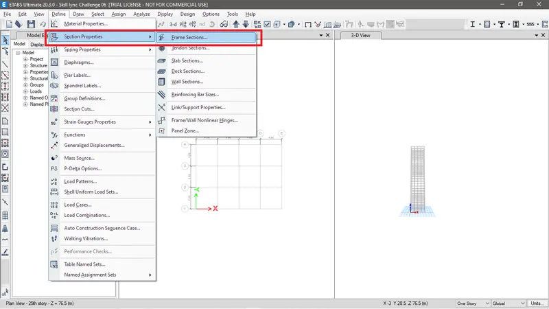
Fig T: Define frame section.
- Click on Add new property as shown in fig U.
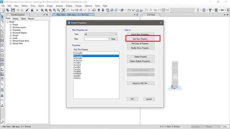
Fig U: Add new property.
- Click on concrete rectangular for frame section as shown in fig V.
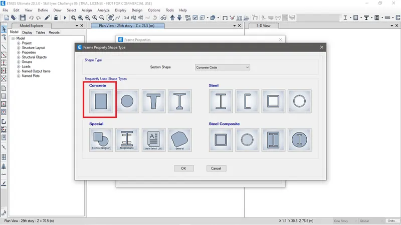
Fig V: Concrete rectangular.
- Now define the beam its name, material type and its dimension and then go to properties modifiers as shown in fig W.
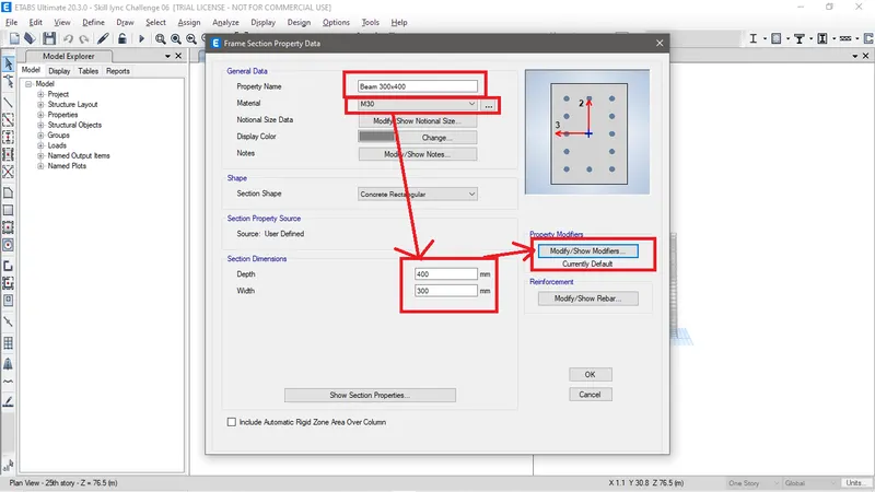
Fig W: Defining concrete beam.
- Now in property modifiers, moment of inertia at 2nd and 3rd axis is to be defined 35% as per IS1893 (Part 01): 2016 clause no 6.4.3.1. Fig X shows that that moment of inertia is defined as 1 at 2nd and 3rd axis because the clause is taken only if we are analysing ultimate design.
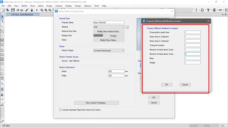
Fig X: Defining Property modefier for beam.
- Now go to Modify reinforcement for concrete beam as shown in fig Y.
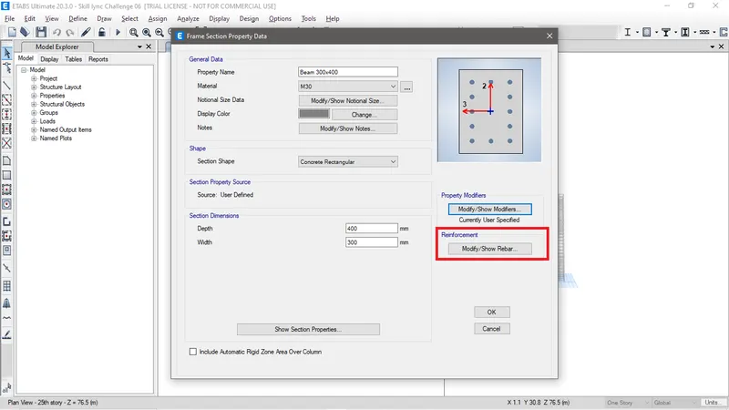
Fig Y: Modify reinforcement.
- Define the reinforcement as per the code and requirement by selecting the M3 Design only (Beam) and providing cover and Rebar material as shown in fig Z and then click OK.
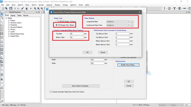
Fig Z: Defining reinforcement for concrete beam.
- Similarly to define concrete column go to add new properties> concrete rectangular and define the name, material type and its dimension and also provide moment of inertia as 70% as specified in IS 1983 clause 6.4.3.1. Fig AA shows the defined column concrete. Here the modier moment of inertial about 2nd and 3rd axis is defined as 1 as we are not designing for ultimate design.
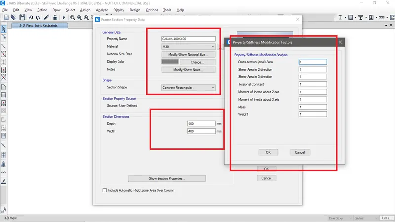
Fig AA: Defining concrete column.
- Now define reinforcement for Concrete column as shown in fig AB.
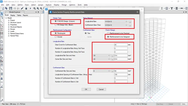
Fig AB: Defining concrete column reinforcement.
- Click on OK to finish. Now we can see in fig AC that the concrete beam and column is added in the frame properties.
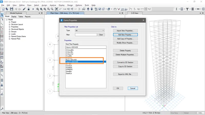
Fig AB: Concrete column and beam added in frame properties.
- Now to define slab section go to Define tab > Section properties > Slab section as shown in fig AC.
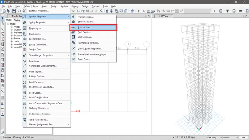
Fig AC: Slab sections.
- Click on add new properties as shown in fig AD. To add new defined slab section.
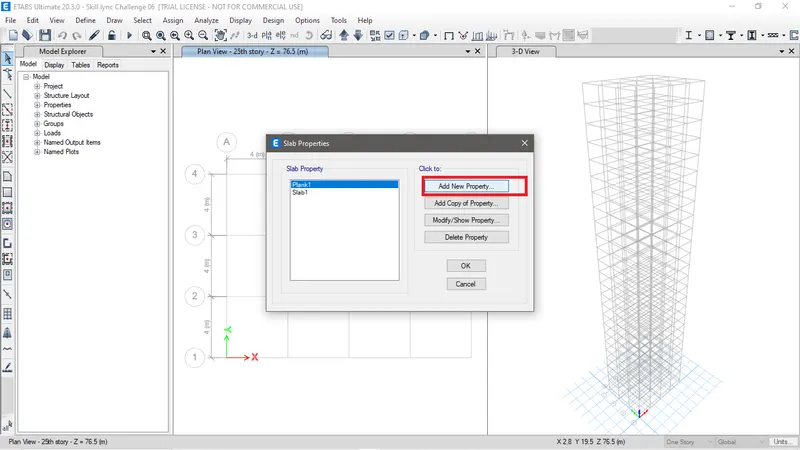
Fig AD: Add new slab section.
- Now define the name, slab material, modelling type- membrane, thickness of the new slab as shown in fig AE.
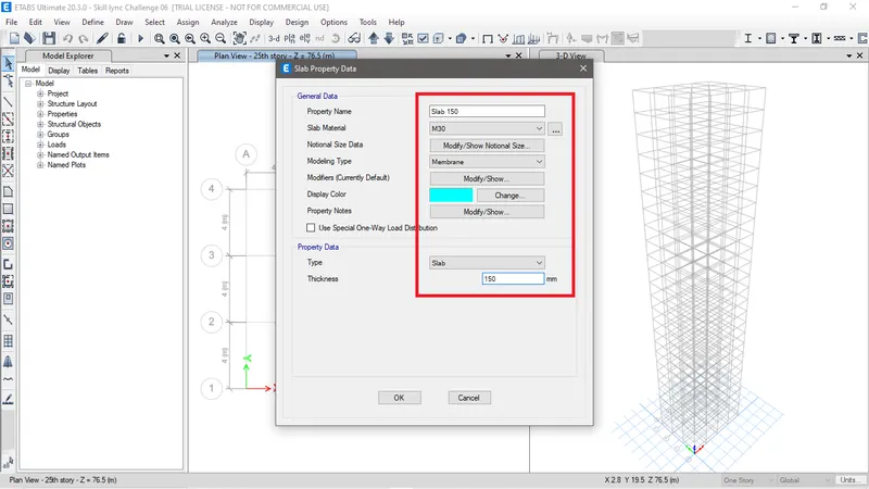
Fig AE: New slab section defined and added.
- Moving ahead to assign the frame section and slab section to the model. To assign column element: Since here the column size is same through out the story we will select all stories option as shown in fig AF.
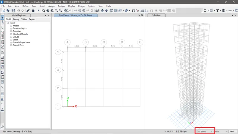
Fig AF: All stories
- Now click on Quick draw column as shown in fig AG, to add the column element.
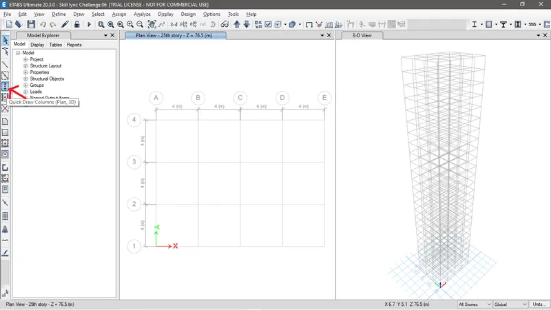
Fig AG: Quick draw columns.
- Now Select the column to be added in the properties and the select the points on grid line to add columns where require as shown in fig AH.
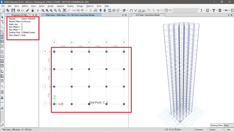
Fig AH: Assigning columns.
- To assign beam clikc on draw beam as shown in fig AI.
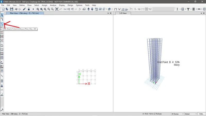
Fig AI: Draw beams.
- Now select the properties of beam and assign it to the gird lines as shown in fig AJ.
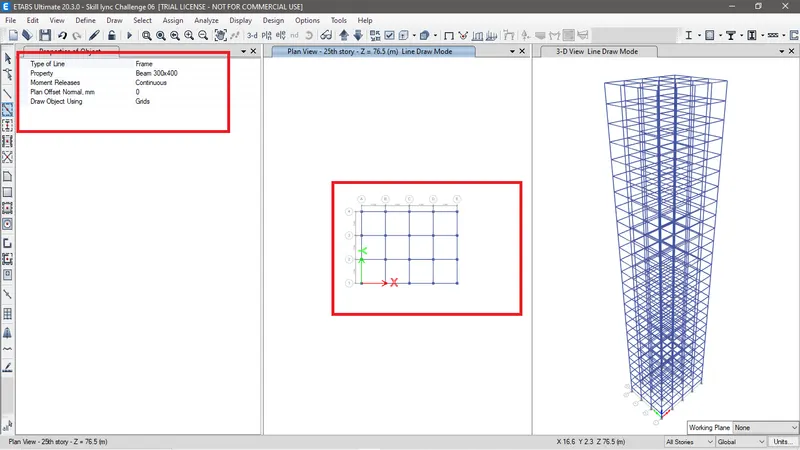
Fig AJ: Beam element assigned to all stories.
- Now to create a slab to all stories except plinth level select Similar stories and click on quick draw floor/walls and select the properties of slab and click on within the grid to assign slab as shown in fig AK.
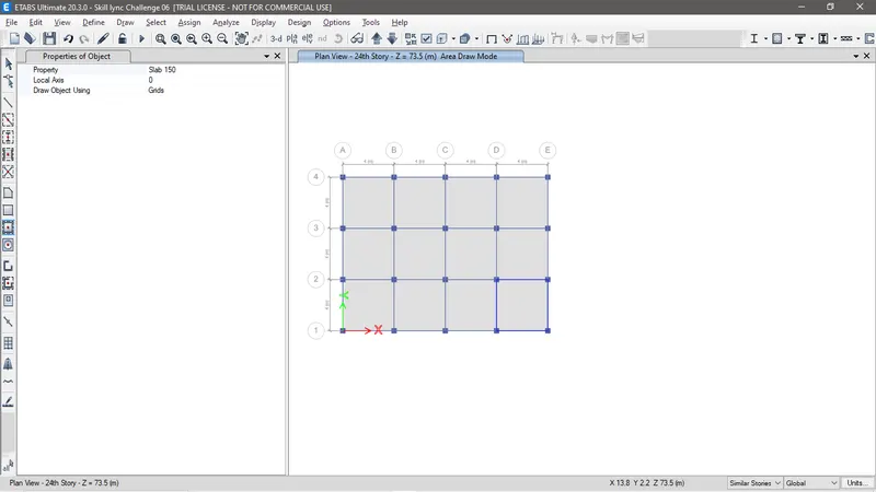
Fig AK: Slab Assigned.
- Moving ahead to assign footing to the base of the structure. To do so, go to plan view and select base and clik on OK as shown in fig AL.
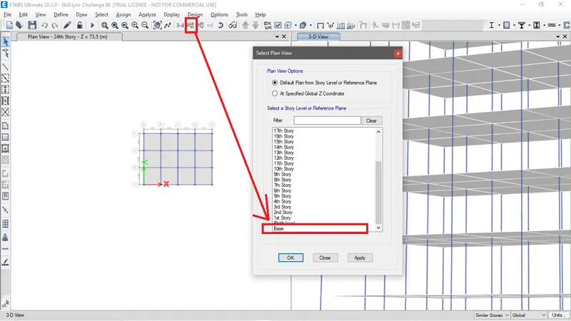
Fig AL: Process to move to Base of the plan.
- Being on a Base plan view, keep the assign story as one story and select all the points to assign fixed joint and then go to Assign tab > Joint > Restraints as shown in fig AM.
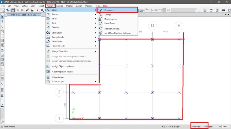
Fig AM: To assign Footing joint.
- Now click on fixed restraint in the fast restraint options and click on apply as shown in fig AN.
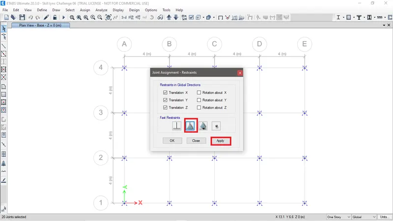
Fig AN: Assigned restraint to the base.
To define Load pattern
- Go to define tab > Load pattern as shown in fig AO.
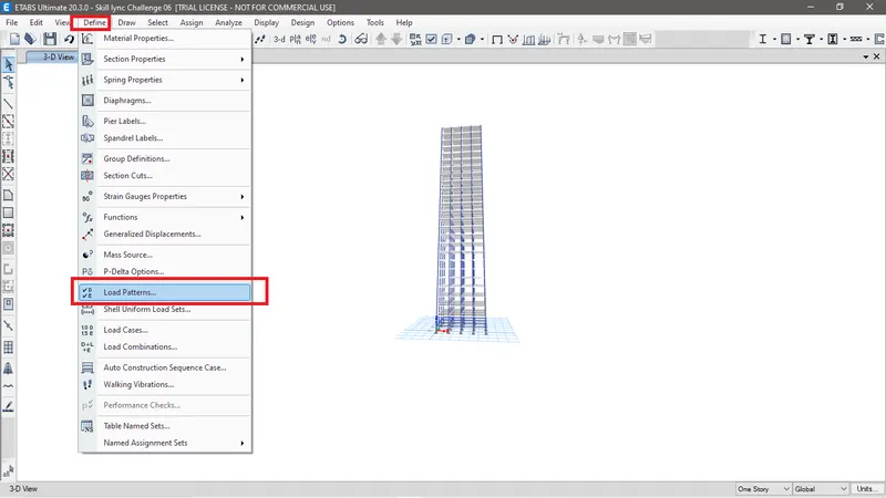
Fig AO: Define load pattern.
- Dead load and live load will be added by default to add again more load pattern type down the details on the first row giving its type and Code and click on Add loads as shown inffig AP.
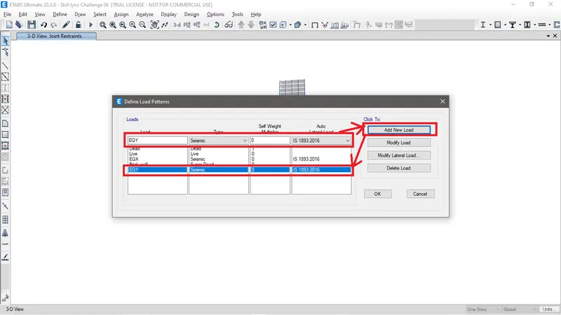
Fig AP: New load defined and added.
- To modify certain load like Earth quake load at X direction or at Y direction. Select the particular load to modify and click on modify lateral load as shown in fig AQ.
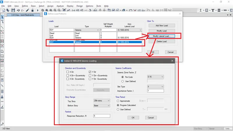
Fig AQ: Modify lateral load
- Now to define the mass source of the load go to Define tab > Mass source. As shown in fig AR
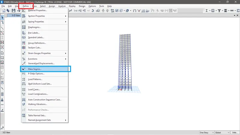
Fig AR: Mass source
- Now click on Modify mass source as shown in fig AS.
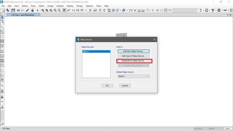
Fig AS: Modify mass source..
- Now add required mass source as per IS code and click on OK, as shown in fig AT.
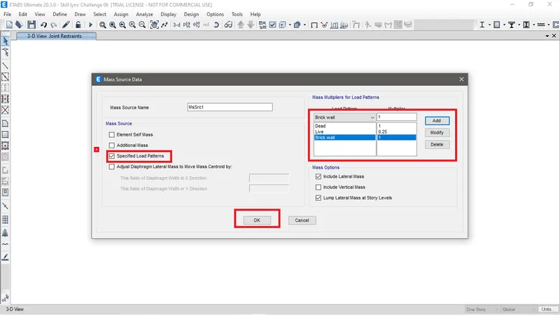
Fig AT: Mass source defined.
- Now to created load combination of concrete frames. Go to Define tab > Load combination. As shown in fig AU.
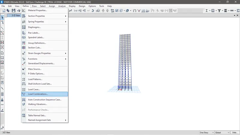
Fig AU: Load combination.
- Add default design combo > Check Concrete frames Design and convert to user define (Editable). As shown in fig AV.
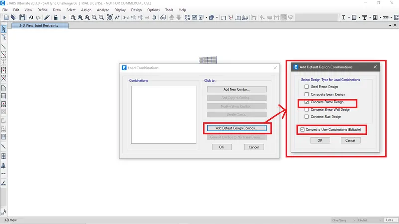
Fig AV: Defining load combination.
- We can see in Fig AW that the load combination is now defined.
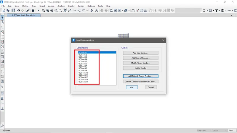
Fig AW: Load combination defined.
To assign load to the structure
- To assign infill wall load to the beam. Go to Select tab > Select > Properties > Frame section. As shown in fig AV.
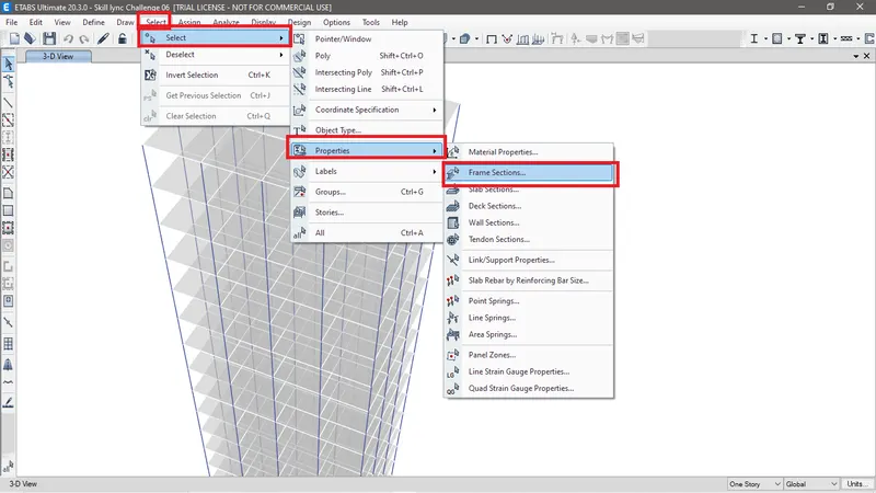
Fig AX: Selection of beam from frame section select option.
- Now select the defined beam for this project and click on Select and then click on Close, as shown in fig AY.
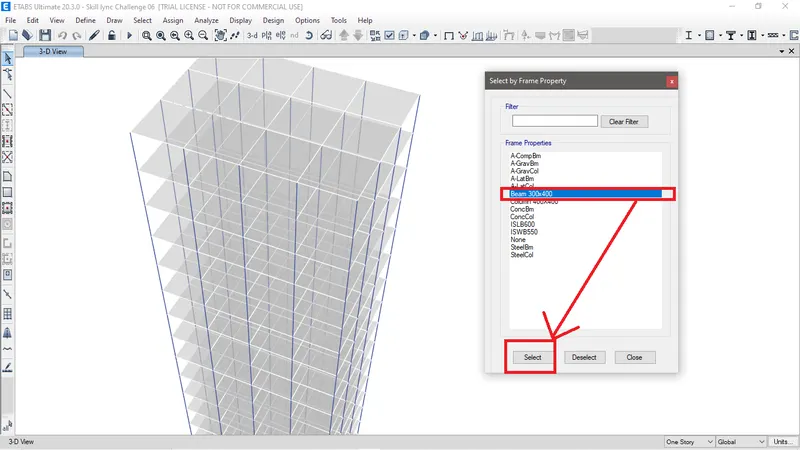
Fig AY: Beam selection.
- We can see in fig AZ that the beam in every floor is being selected.
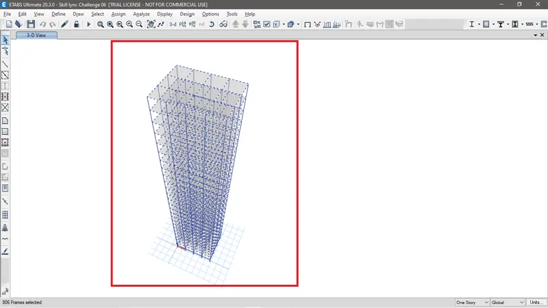
Fig AZ: Beams selected.
- Now to assign in fill walls load to the selected beam go to Assign tab > Frame load > Distributed. As shown in fig BA.
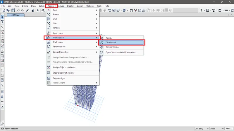
Fig BA: Frame load assigning.
- Now define the load by selecting load pattern as Brick wall and load 10Kn/m.
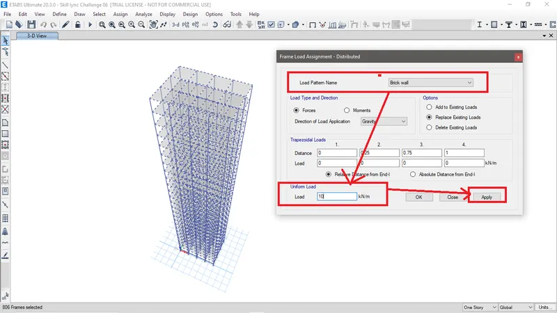
Fig BB: Defining brick wall load.
- Fig BC shows that the infill brick wall is assigned to the beam.
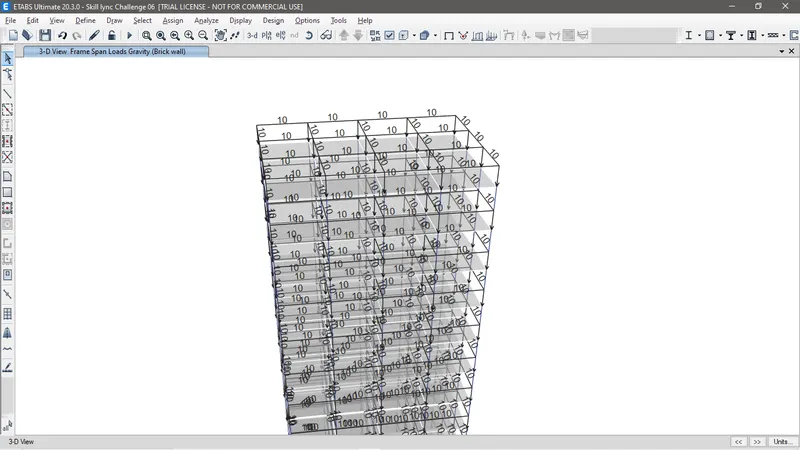
Fig BC: Infill wall load assigned to the beam.
- Similarly to assign live load to the slab first select slab from select tab> properties and Slab section and then later go to Assign tab > Shell Load> Uniform, as shown in fig BD.
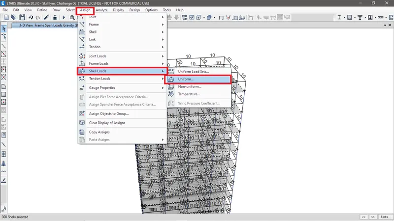
Fig BD: Assigning shell load.
- Define the live load to the shell as shown in fig BE.
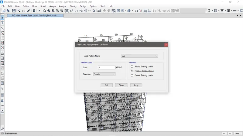
Fig BE: Defining shell load.
- Live load assigned to the slab as shown in Fig BF.
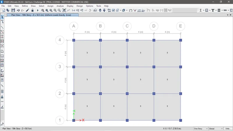
Fig BF: Live load assigned to the slab.
- Now select the slab in all floors again and go to Assign>Shell> Diagphram. As shown in fig BG.
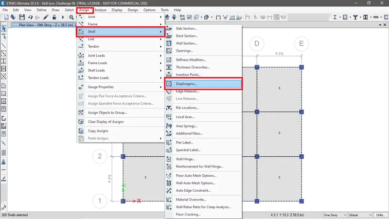
Fig BG: Assigning of Diagphrams.
- Select D1 and then click on Apply > Close. As show in Fig BH.
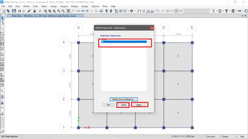
Fig BH: Selection of shell diagphram to assign.
- Diagphram is being assigned to the shell, as shown in fig BI.
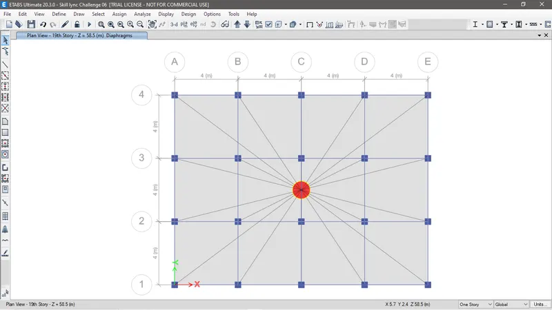
Fig BI: Diagphram assigned to the shell.
Now the loads are defined and assigned. Moving ahead to run and seek the result of the analization.
- Click on Play option in the ribbon to run analysis of the structure designed as shown in fig BJ.
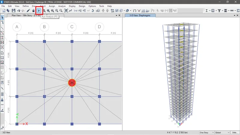
Fig BJ: Run analysis.
- After Run Analysis we can notice the defelection in slab in 3d view of the structure which shows that the run analysis is being completed, as to be seen in Fig BK.
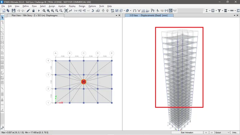
Fig BK: Run analysis completed.
For following check:
1) Check if the translational fundamental natural period of vibration in both the x and y direction is approximately:
- In model explorer window Go to Table > Analysis result > Structure output > Modal information> Right click on Modal period and frequencies and then click on show table as shown in fig BL.
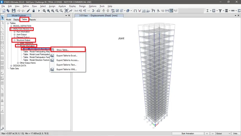
Fig BL: Modal Explorer- Modal period and frequencies.
- From the Fig BM we can see that the Period of Mode 01 is 5.133 sec abd Mode 02 is 4.835. Since it doesn't satisifies the check, Hence the model is being found to be designed with error. The error in this design is that the column size is not defined as per the given design which is to be seen in Fig BN. The column size should be 800X800 and not 400X400.
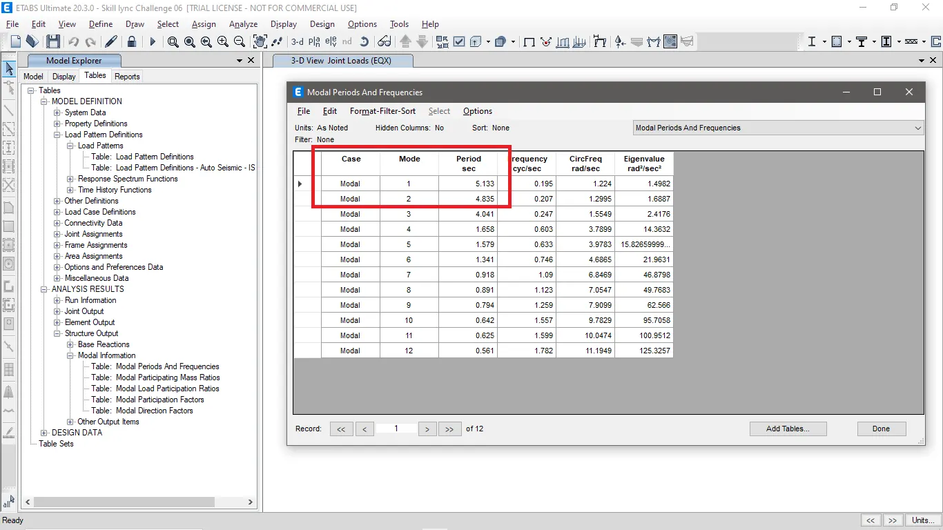
Fig BM: Modal period and frequecies table showing unsatisfactory result.
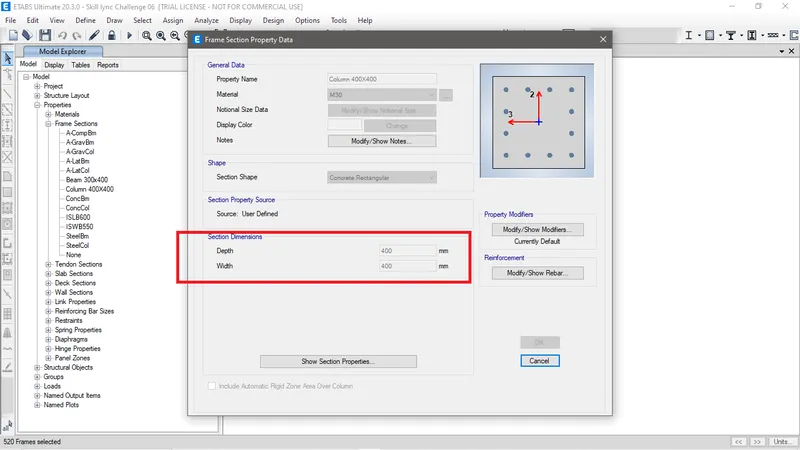
Fig BN: Incorrect column dimension defined.
- Now to achieve satisfactory result of modal period, we will now change the column size to 800X800 and re run analysis and check the modal period.
- After making necessary changes Modal period is found to be satisfactory that is Mode 01 is 4.416 and Mode 2 is 4.222, as shown in fig B0. Hence the model is perfectly designed.
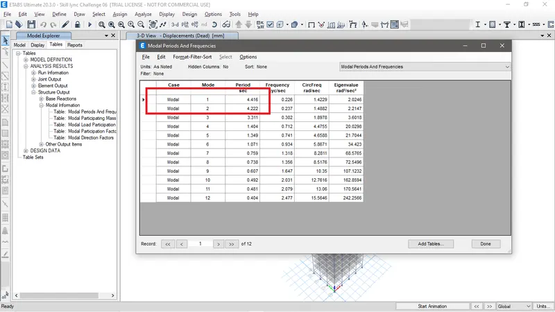
Fig BO: Satisfactory modal period results.
2) Check if the following provision in Table 5 of IS 1893 (part 1) – 2016, on torsional irregularity satisfied:
From table 05 of IS 1893 (Part 01) states that the natural period corresponding to the torsional mode of oscillation must be less than the two fundamental translational modes of oscillation along each principal plan directions.
- From Fig BO we can see that the Modal 3 period - 3.311 sec is less than Modal 01-4.416 sec and Modal 02-4.222 sec. Hence it satisfies torsional irregularities.
3)Check if the two provisions of clause 7 in Table 6 (shown below) of IS 1893 (part 1) – 2016, regarding vertical irregularity is satisfied
As per IS 1893 (Part 1)-2016 clause 7 in Table 6 states as shown in fig BP.
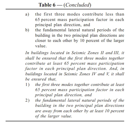
Fig BP: IS 1983 Part 1 Table 06 for Vertical irregularities.
- Now to view the modal mass participation of the model. Go to Modal participarting mass ratios and we can see the table is displayed as shown in fig BQ.
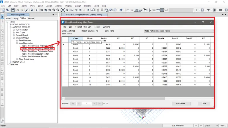
Fig BQ: Modal Participating Mass ratios table.
- From the Fig BQ we can see that Modal 1 is resulted to be having 80.42% of mass participation. Hence it satisfies the 1st criteria of the vertical irregularities.
- But the Difference between the period of moda1 and modal 2 is less than 10%. Hence it disatisfies the 2nd criteria of the vertical irregularities.
3) Check if provision on inter-storey drift limitations in clause 7.11.1.1 satisfied. Please note that this check is for Serviceability Limit State and hence is for situation when stucture is subjected to unfactored seismic base shear.
The above clause states the followin shown in fig BR
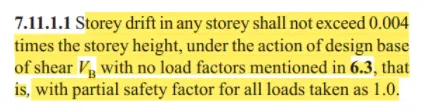
Fig BR: Clause 7.11.1.1 Inter storey drift.
- Now in order to check this criteria in Etabs. Go to Display tab> Storey response plots. As shown in Fig BS.
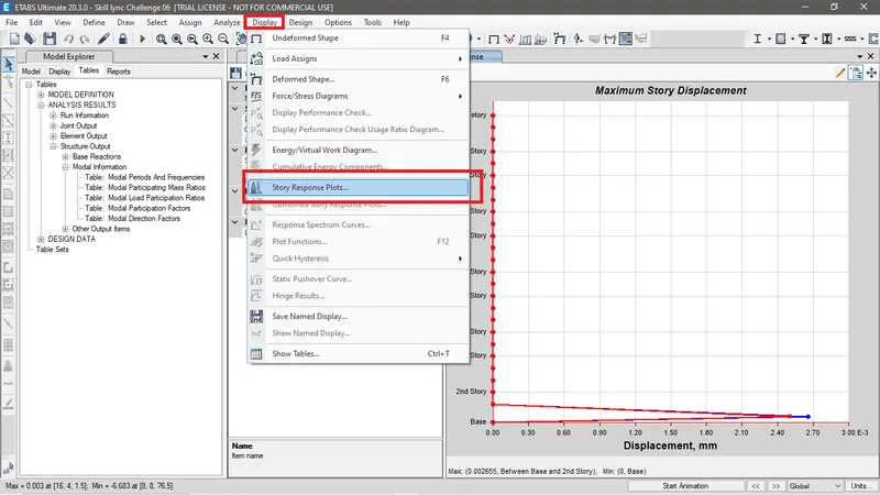
Fig BS: Storey response plot.
- Now select Display type- Max storey drift and Case/Combo as EQX or EQY to check the drift. Fig BT shows graph of storey drift of EQX and Fig BU shows graph of storey drift of EQY combo. From the graph is to be found that both the drift is more than 0.004. Hence this model satisfies inter storey drift criteria.
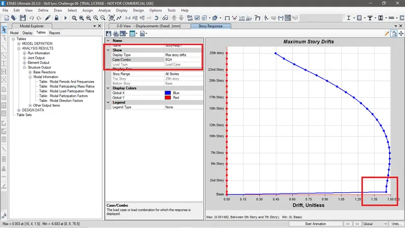
Fig BT: Satisfied storey drift result in Earth quake load at X direction.
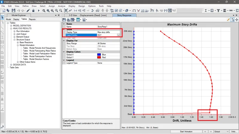
Fig BU: Satisfied storey drift result in Earth quake load at Y direction.
Conclusion:
In this task the model is being created in the Etabs as described and following checks are resulted :
- Check if the translational fundamental natural period of vibration in both the x and y direction is approximately:
T x 1 T y 1 - Check if the following provision in Table 5 of IS 1893 (part 1) – 2016, on torsional irregularity satisfied: Satisfied.
- Check if the two provisions of clause 7 in Table 6 (shown below) of IS 1893 (part 1) – 2016, regarding vertical irregularity is satisfied
- Provision 01 - Satisfied.
- Provision 02- Not satisfied.
- Check if provision on inter-storey drift limitations in clause 7.11.1.1 satisfied. Please note that this check is for Serviceability Limit State and hence is for situation when stucture is subjected to unfactored seismic base shear-Satisfied.