Modelling of 25 storey building with the specified properties using ETABS
AIM: ETABS modeling of a 25-storey building
INTRODUCTION:
Structural Element Sizes
- Beams: 300 × 400 mm
- Columns: 800 × 800 mm
- Slab: 150 mm thick
Material Properties
- Grade of Concrete: M30
- Grade of Steel Reinforcement Bars: Fe 415
Loading
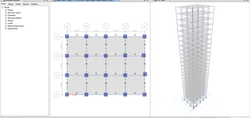
- Dead Load on beams from infill wall: 10 kN/m (Let us assume the same for roof floor in view of parapet)
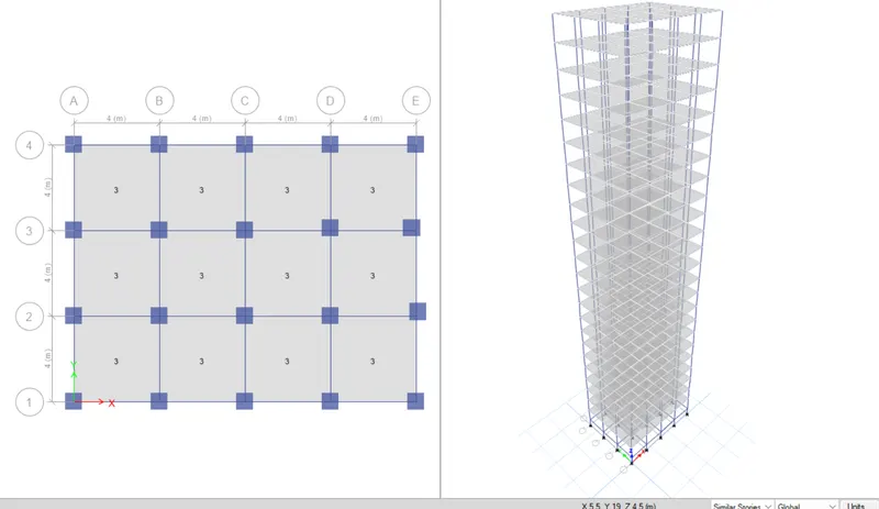
- Live load on the floor : 3 kN/m2 (Let us assume the same for roof floor)
a) Buildings are assumed to be pinned at the base
b) All columns in all storeys are of the same size
c) All beams in all stories are of the same size
d) Building is located on Soil type-II and in Zone-III. Assume other factors if required.
PROCEDURE:
- select a new model set the units as IS set the steel and concrete code also as per IS code.
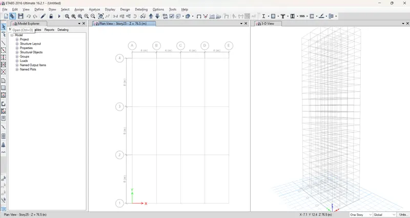
- select the grids in X direction with 4m spacing in Y direction also 4m spacing with 4rows.
- edit story data as place plinth beam as 1.5m height make story one as a base story, add 24 stories with 3m elevation, set the stores with the base story of story 1.
- define the material as concrete. click define select material choose M25 click ok.
- same as defining rebars as fe415.
- select the properties choose frame properties add new -- name as B400X300 material as M25. click ok,
- same as adding frame properties name as C800X800 choose material M25, and modify the properties rebar as fe415. add cover as 40mm click ok.
- design-- slabs-add new slab named as slab150 and choose material as a membrane. thick ness as 150mm click on ok.
- define the loads-- define select loads-- dead load, live loads, wind loads, and EQX EQY seismic loads.
- when adding EQX modify the choose Xdirection only, EQY modifies choose the Ydiretion only and choose the soil factor as 0.16 and zone as ZONE III
- choose define add mass source named as mass source click with loads of dead 1, live load 0.25. wall load is 1factors.
- Check the load cases to properly load are there or not,
- define -load combinations, choose frame design, select auto combinations, click on ok.
- choose the quick column drawing option, choose the C800X800 place the columns at the required places,
- same as columns place the beams also by choosing B400X300 ok,
- add slab also by choosing to add floors option click on the grids make sure to select the similar stories,
- select all beams by select properties-frames sections B400X300 and assign the frame loads -uniform-10kn/m2,
- same select the slabs by properties -slab sections-choose S150 assign the shell loads as 3kn/m2.
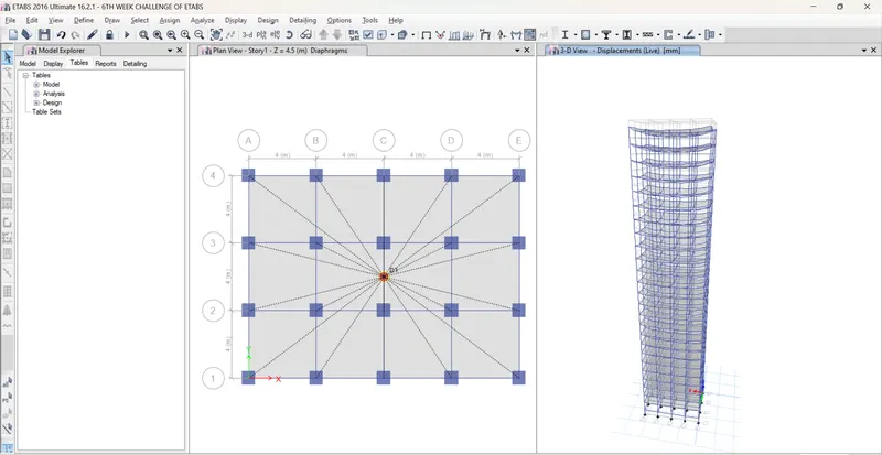
- select the slabs and assign the diaphragm to slabs by choosing similar stories.
- CLICK on run analysis,save the file , check the tables -model information choose the values, and choose as shown in tables,
- check the drifts also.
| Criteria | Desirable solution | Result | |
| fundamental translation natural period | X-direction | 4.4second | 4.42 |
| Y-direction | 4.2 second | 4.26 | |
| torsional irregularity | Is1893-2106(part-1) table5 | torsional mode time period should be lesser then X and Y direction time periods. | yes |
| vertical irregularity | Is1893-2106(part-1) table6 | first 3modes should be greter than 65% contribution | yes |
| fundamental layeral natural periods in two principal plane directions are away from each other by at least 10% | no | ||
| inter storey drift | Is1893-2106(part-1) clause 7 | storey drifts shall not exeed 0.004times the story height for base shear with no load factor(4x10^-3) | yes |