Modelling of 25 storey building with the specified properties using ETABS
AIM: MODEL A 25 STOREY BUILDING ON ETABS WITH STRUCTURAL PROPERTIES AS SPECIFIED BELOW. GROUND FLOOR OR PLINTH FLOOR LEVEL CAN BE TAKEN AT A HEIGHT OF 1.5 METERS FROM THE BASE EACH OF THE SUCCESSIVE 25 STOREY HAS A STOREY HEIGHT OF 3 METERS
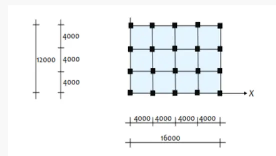
GIVEN:
- STRUCTURAL ELEMENT SIZES
- BEAMS: 300 X 400 MM
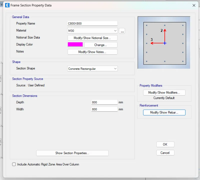
- COLUMN: 800 X 800 MM
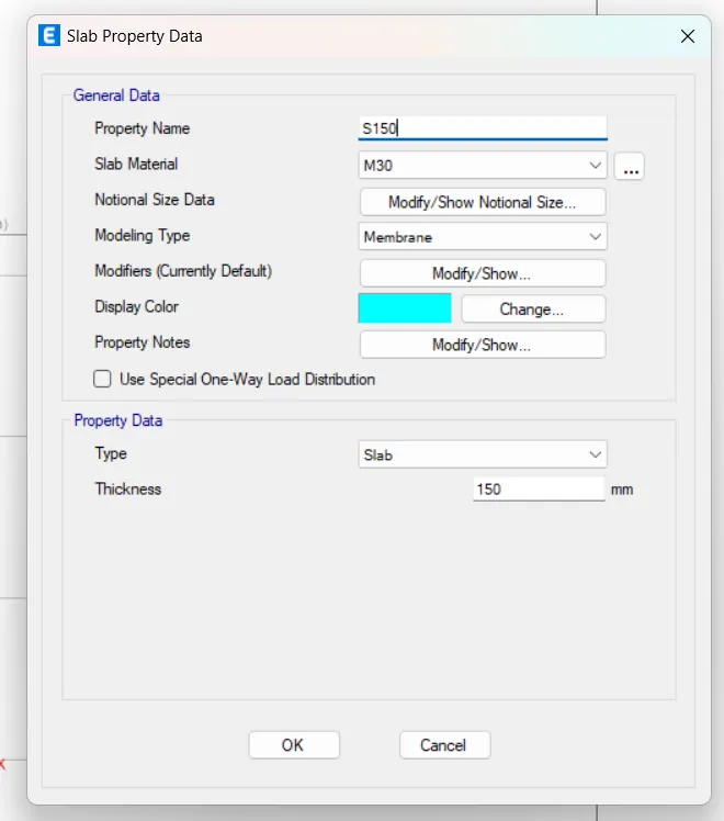
- SLAB: 150 MM THICK
- MATERIAL PROPERTIES:
- GRADE OF CONCRETE: M30
- GRADE OF STEEL REINFORCEMENT BARS: Fe415
- LOADING:
- DEAD LOAD ON BEAMS FROM INFILL WALL : 10 KN/M (LET US ASSUME THE SAME FOR ROOF FLOOR IN VIEW IF PARAPET)
- LIVE LOAD ON FLOOR: 3 KN/M^2 (LET US ASSUME THE SAME FOR ROOF FLOOR)
- BUILDING ARE ASSUMED TO BE PINNED AT THE BASE
- ALL COLUMN IN ALL STOREY ARE OF THE SAME SIZE
- ALL BEAMS IN ALL STOREY ARE OF THE SAME SIZE
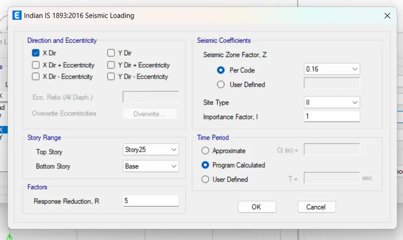
- BUILDING IS LOCATED ON SOIL TYPE-II AND IN ZONE-III ASSUME OTHER FACTORS IF REQUIRED
FIND:
- CHECK IF THE TRANSLATION FUNDAMENTAL NATURAL PERIOD OF VIBRATION IN BOTH THE X AND Y DIRECTION IS APPROXIMATELY: Tx1 = 4.4 second Ty1 = 4.2 second
- CHECK IF THE FOLLOWING PROVISION IN TABLE 5 OF IS 1893 (PART 1) – 2016 ON TORSIONAL IRREGULARITY SATISFIED
- CHECK IF THE TWO PROVISIONS OF CLAUSE 7 IN TABLE 6 (SHOW BELOW) OF IS 1893 (PART 1) -2016, REGARDING VERTICAL IRREGULARITY IS SATISFIIED
STPES:
- Open the ETABS software and click on the new model to create a new model
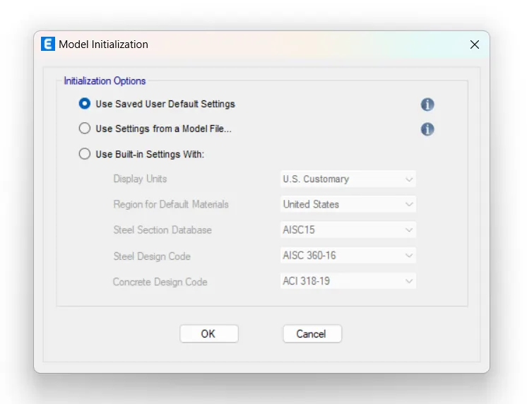
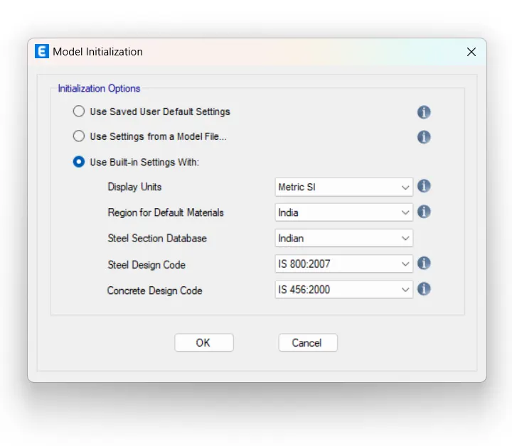
- Then go to the use built in setting and add the unit, material region, steel code and concrete code in model initialization panel and then click ok
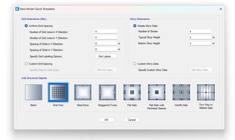
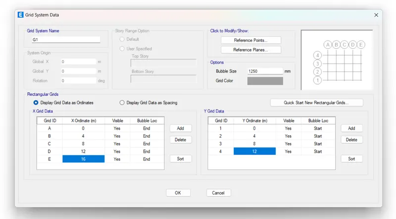
- Then after new window will open new template model in that window go to costume grid setting and edit the grid as per the requirements
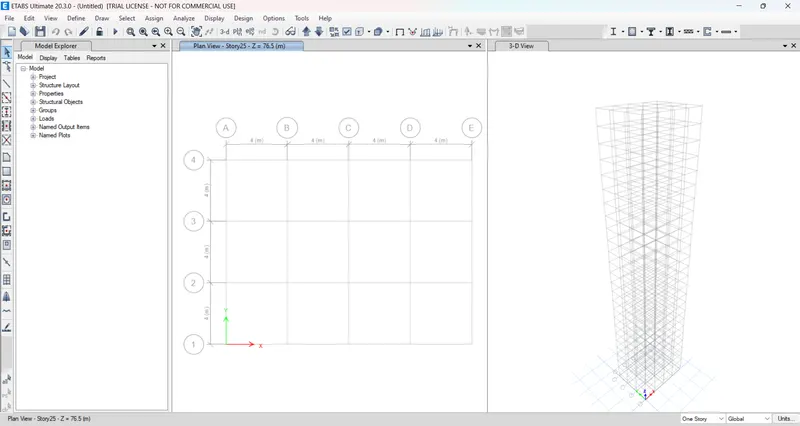
- We are making 5 grids in x direction and 4 grids in y direction with the equal spacing of 4m
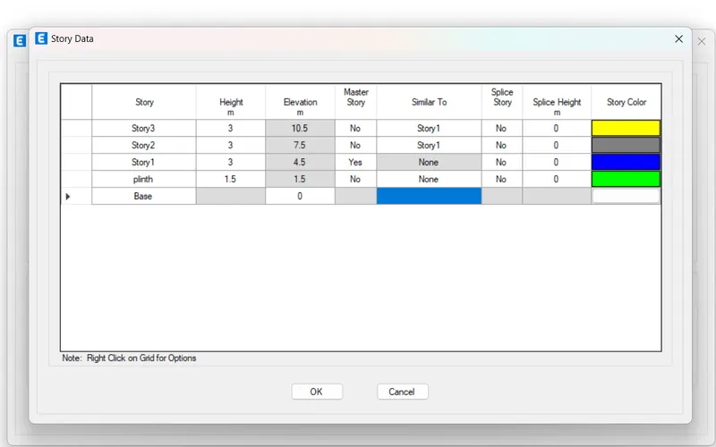
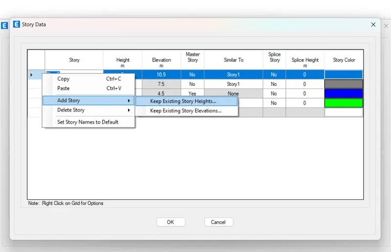
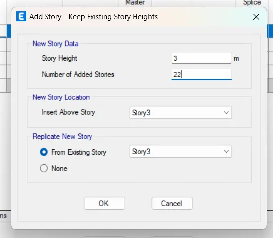
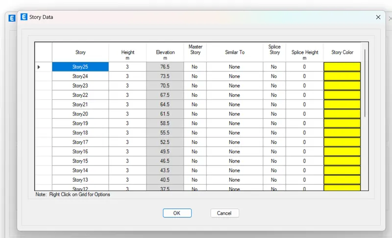
- Then go to custom story data to add the floors in the model
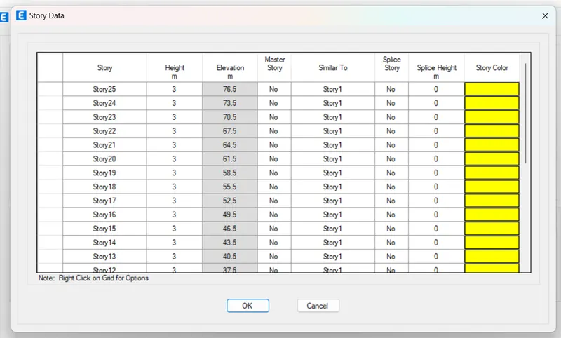
- Add 25 storey in it as per the requirements then make a starey one as a master storey so that changes make to the storey one can replicate to the all storey above
- Make a all story similar to story 1 and then press ok
- After that two view will open one plan view and second is 3d view
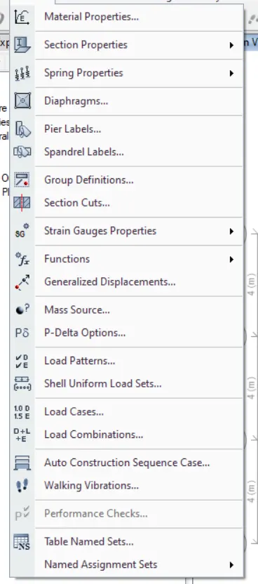
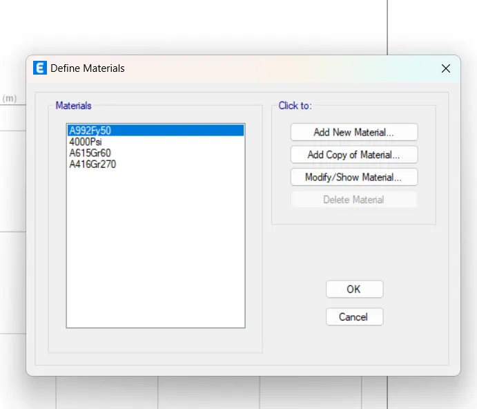
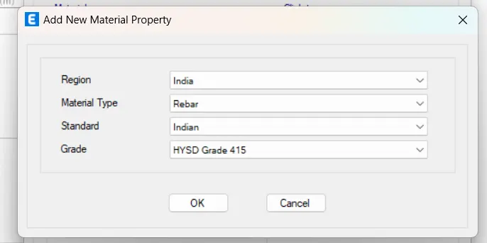
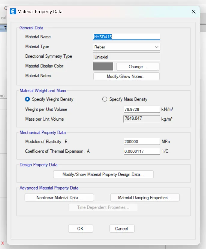
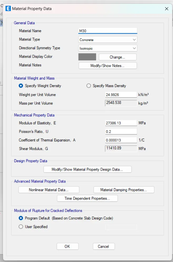
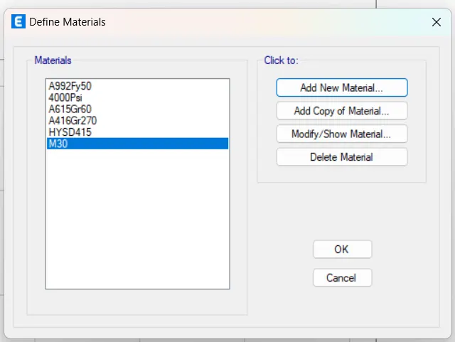
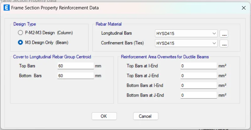
- Then add the material property by going define tab and open material property and create a rebar of HYSD415 and the M30 concrete
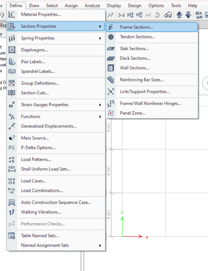
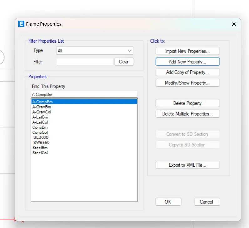
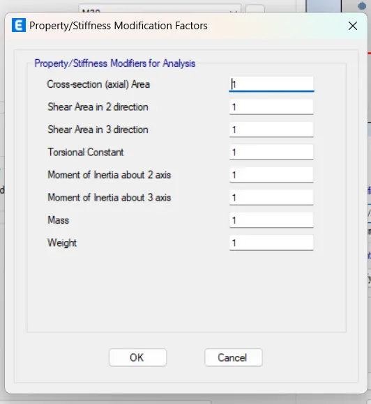
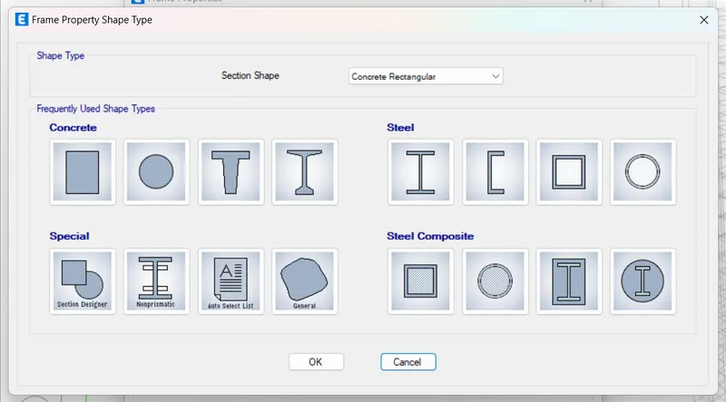
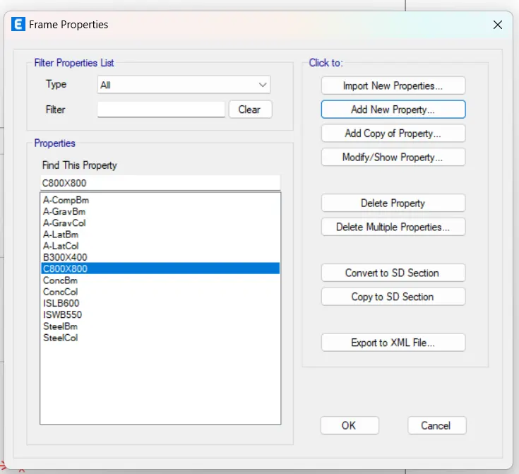
- Then go to the frame section and create a new beam with the design details of M30 concrete and HYSD415 steel.
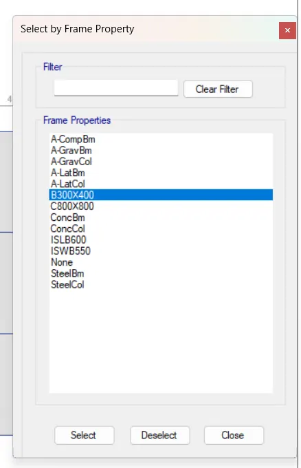
- Create a beam with the depth 400 and with of 300 and press ok then beam will create
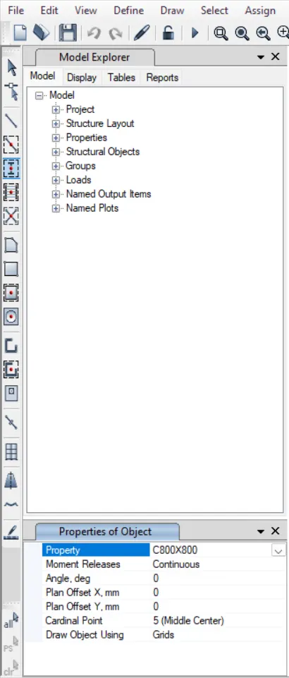
- Similarly create a column of the size C800X800 and press ok
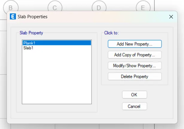
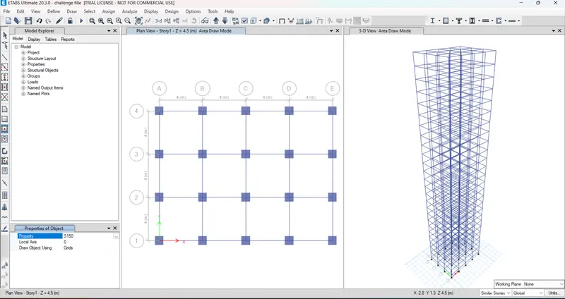
- Then to create a slab of 150 thickness go to the slab definition and create a slab S150
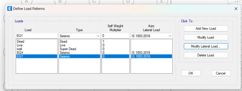
- Then create the load dead load, live load, wall load and earthquake load in x-direction and earthquake load in y-direction
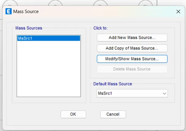
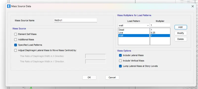
- Then define the mass percentage of the live load and dead load and wall load as per IS code
- Then go to the load case in define tab to see the load case as per given cheeked it
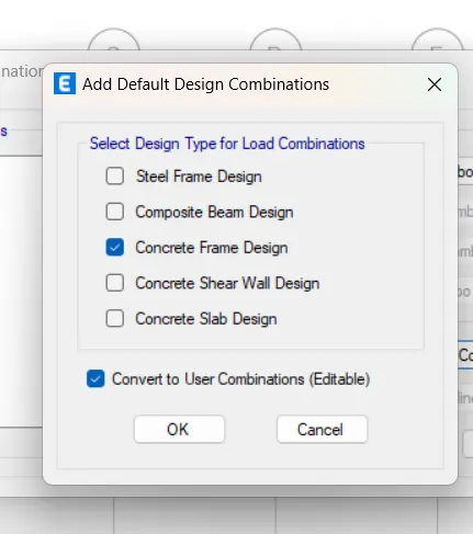
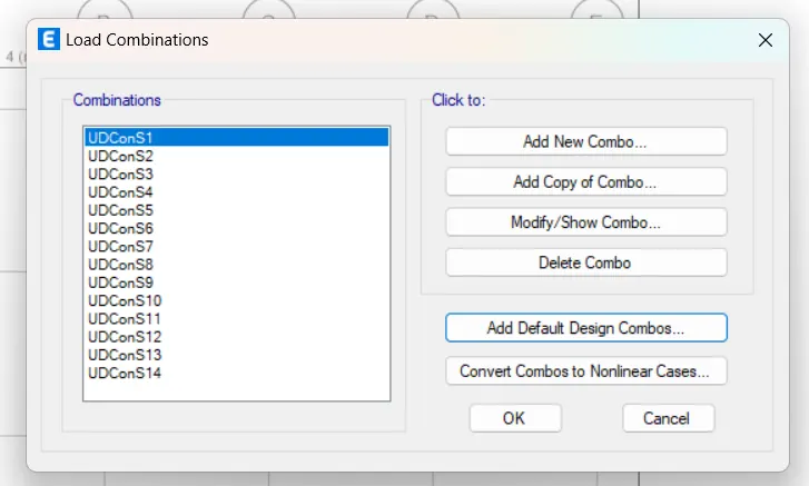
- Then create the load combination for analysis
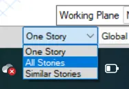
- After that the modelling stage will start to create the column first get select the quick draw option and select the all storey option
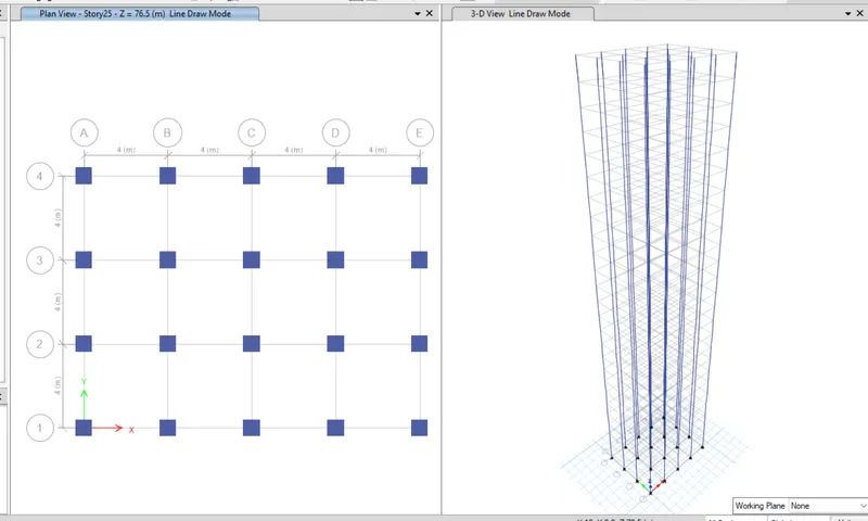
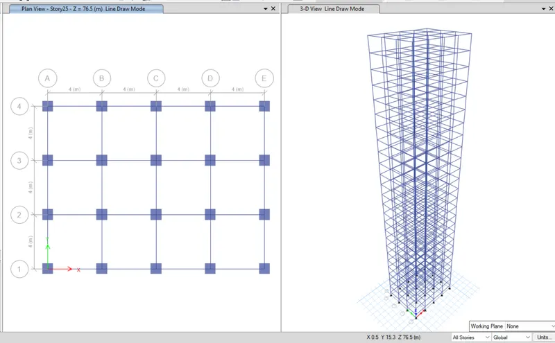
- Then draw the column at the all the intersection of the grid
- Then select the beam and create the beam between all the column as per the requirement
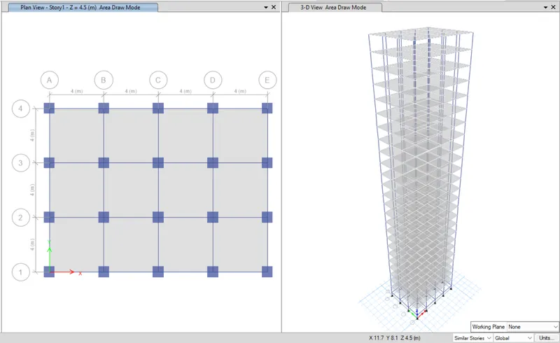
- Then to create the slab first go to the first storey and select single storey option so that the there is slab created at the plinth level of the building
- Then to add the load first select the all the beam by using select option in ribbon tab
- Then assign the load of 10KN/m to the all the selected beam
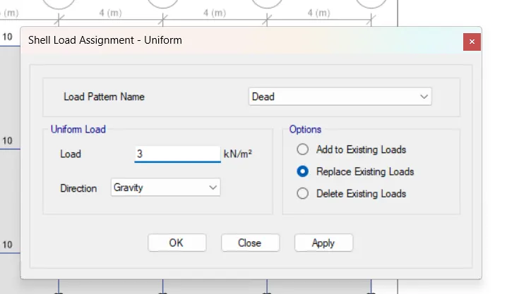
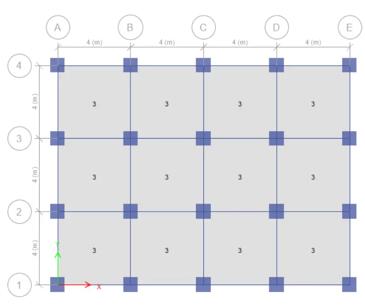
- Then assign the load of 3kN/m^2 to the all the slab by selecting slabs as similar as beams
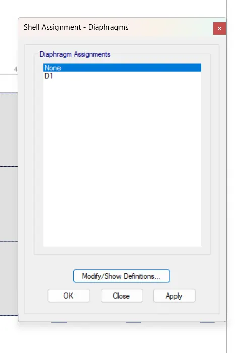
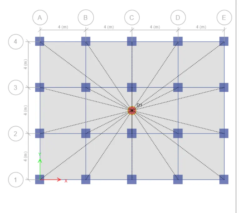
- Then assign the diaphragms select all the slab assign it
- After all the things are completed run the analysis before that save the model if your not saved it
- Analysis is completed result is as per following
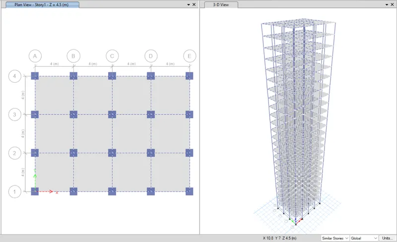
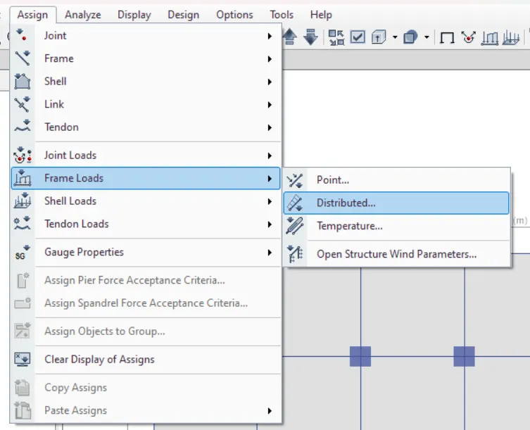
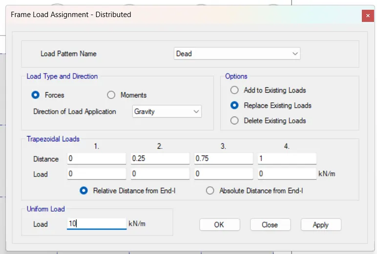
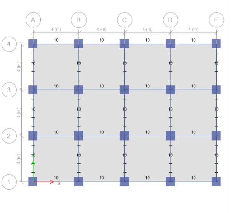

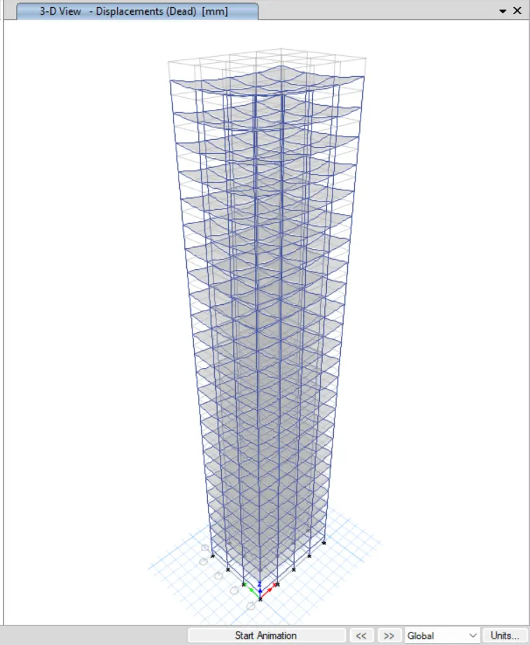
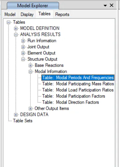
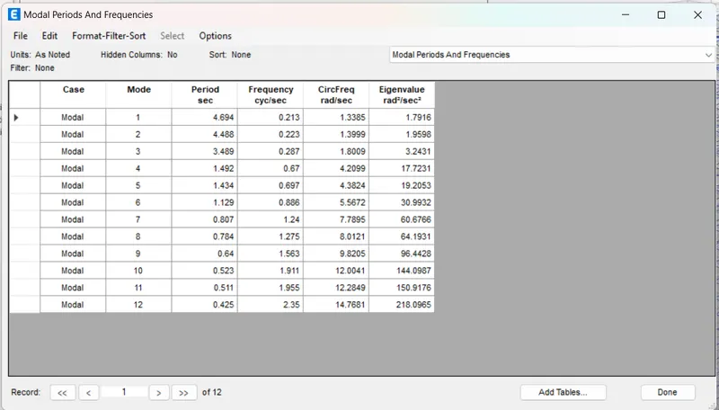
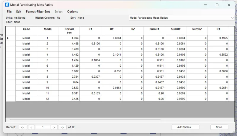
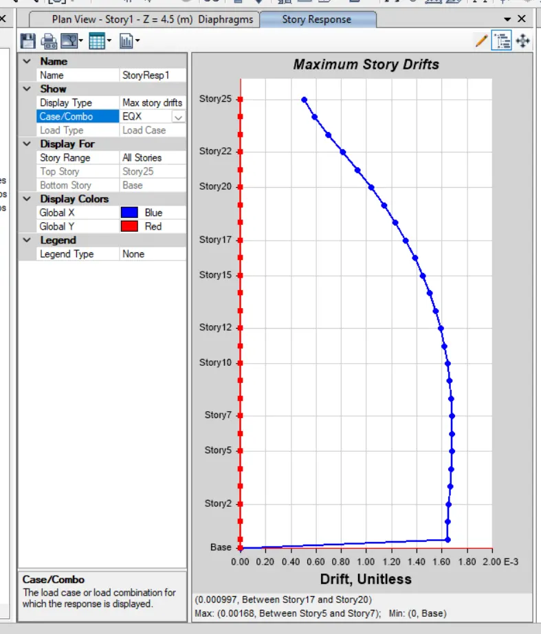
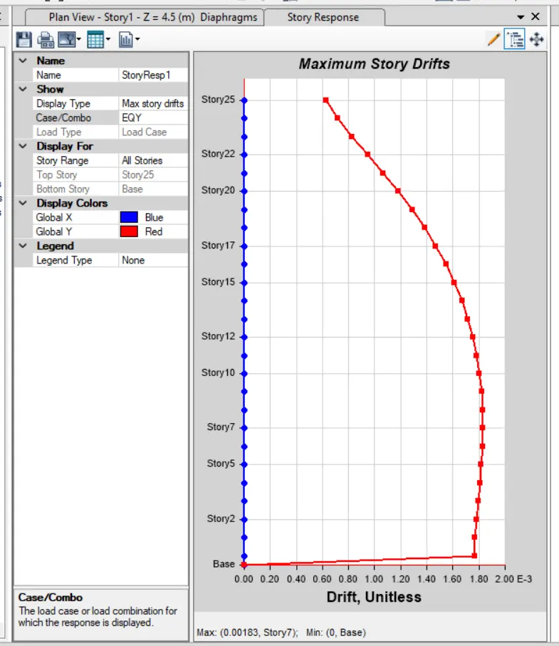
RESULT:
|
criteria |
|
Desirable solution |
Exercise result |
|
Fundamental translational natural period |
X -direction |
4.4 second |
4.6 |
|
Y – direction |
4.2 second |
4.4 |
|
|
Torsional irregularity |
IS 1893-2016 (part-1) table 5 |
Torsional mode time period should be lesser than X and Y direction time periods |
yes |
|
Vertical irregularity |
IS 1893-2016 (part-1) table 6 clause-7 |
First three modes together should contribute at least 65% in mass participation factor in each principal direction |
yes |
|
Fundamental lateral natural periods in two principal plane directions are away from each other by at least 10% |
no |
||
|
Inter-story drift |
IS 1893-2016 (part-1) clause-7 11.1.1 |
Storey drift shall not exceed 0.004 times the storey height for base shear with no load factors (4x10^-3) |
yes |