Modelling of 25 storey building with the specified properties using ETABS
Aim:
Model a 25-story building on ETABS 2023 with structural properties as shown below. The level of the ground floor or plinth can be taken at a height of 1.5 meters from the base. Each of the 25 consecutive floors has a floor height of 3 meters. :
Procedure:
Step 1:
Open the ETABS software.
Click the File menu and select Create New Model.
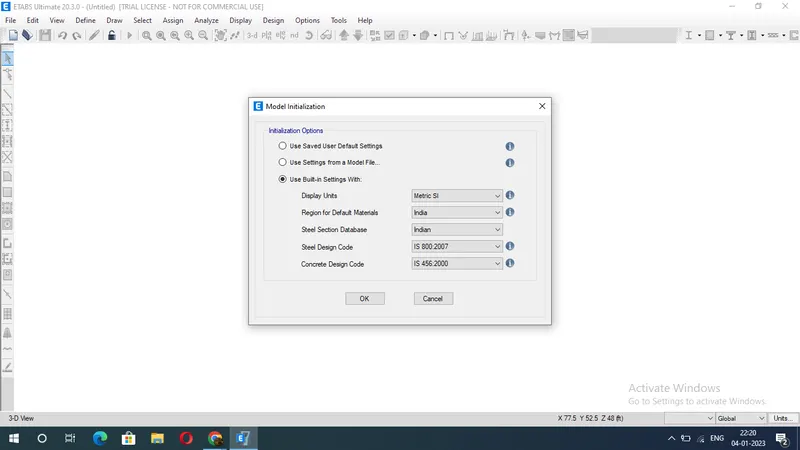
After selecting a new model, a dialog box will appear as Model Initialization.
Select Built-in Settings and select display units and codes.
Step 2:
After initializing the model. In the New Model Quick Templates dialog box, select the Grid and Story inputs.
In this dialog, select the custom grid spacing and custom story data that will be used to provide the above inputs.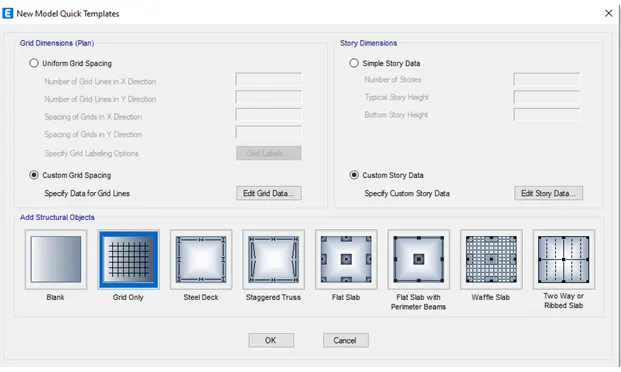
Enter the X grid data as 5 numbers at 4 meters and the Y grid data as 4 numbers at 4 meters.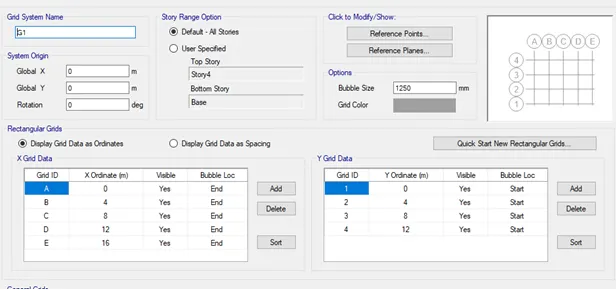
Click on the story data dialog, add a story, and add 22 more stories.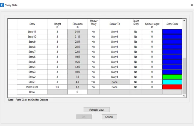
Maintain full story height of 3m and plinth level of 1.5m.
Create the 1st story as the main story.
Keep all stories similar to the first story.
Select the material properties on the Definition tab.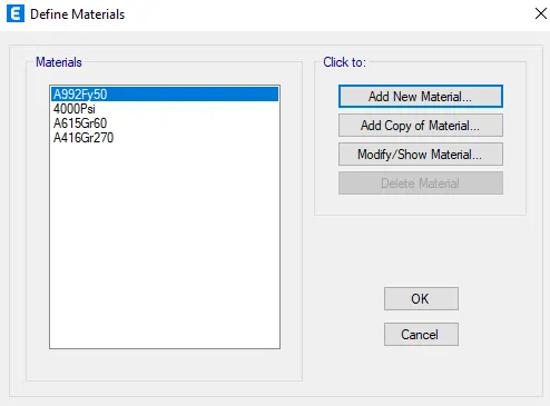
Define the concrete materials as M30 grade and the transverse reinforcement steel as grade 415 and the longitudinal reinforcement as grade 500.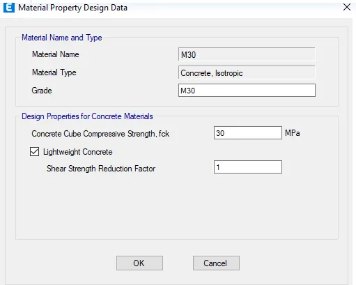
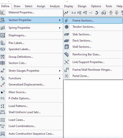
On the Define tab, select Section Properties.
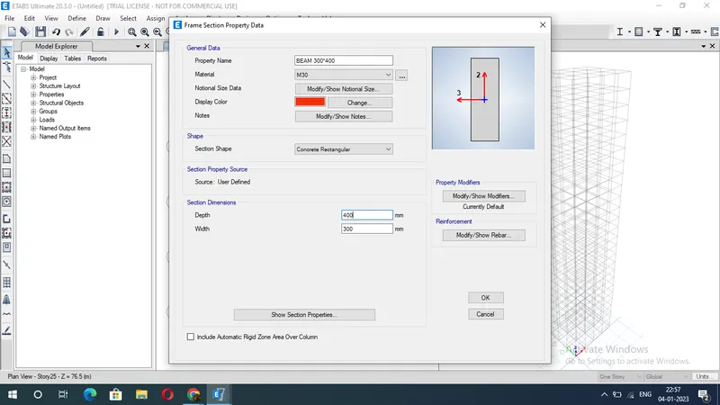
Click on the frame section and create a new property as beam and enter values like 300X400mm.
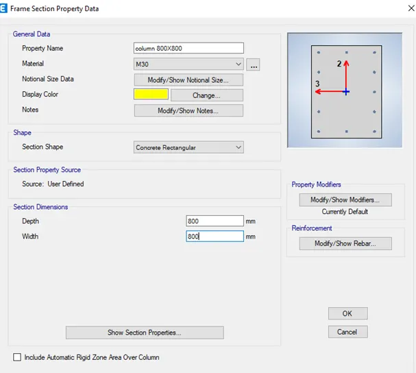
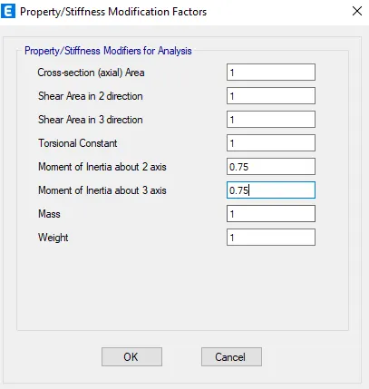
Then define the column properties as 800X800mm and slab thickness as 150mm.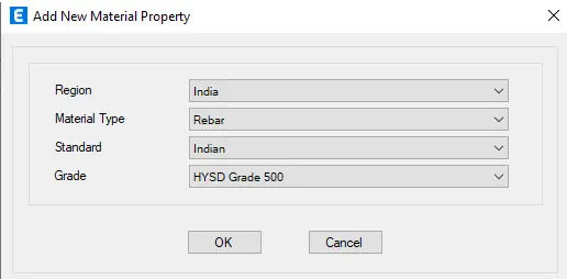
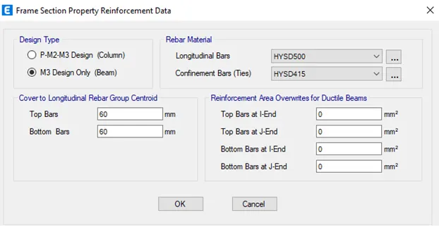
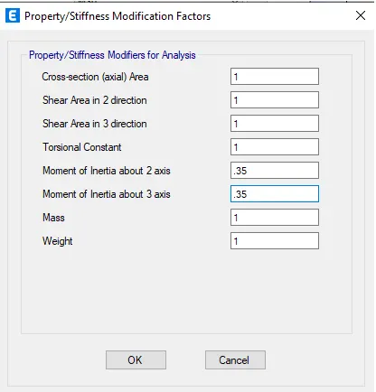
Column 800 x 800 mm:
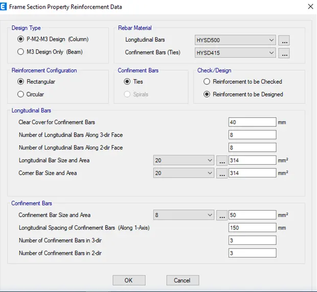
slab 150 mm thick plate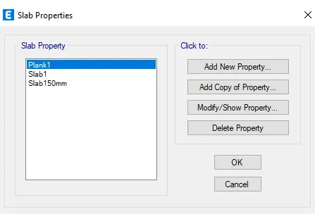
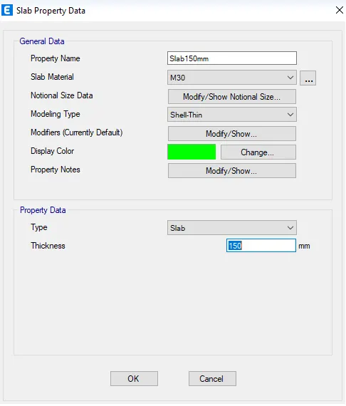
Draw an 800mm X 800mm column at the intersection of the horizontal and vertical grid and beams
with the Quick Draw tool.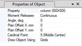
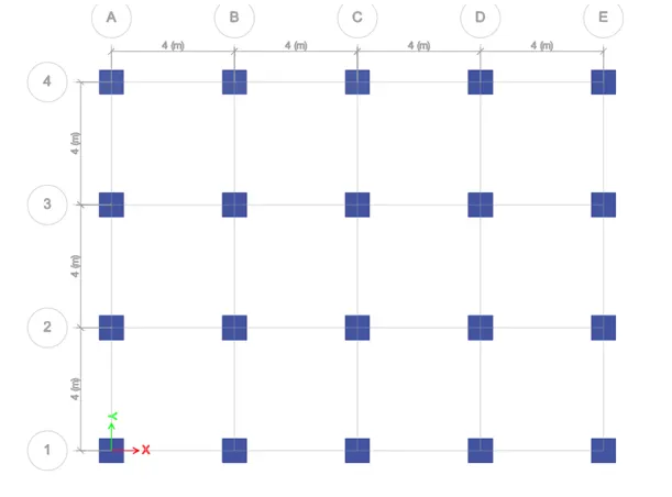
Draw a 150mm thick floor using the Quick Darw tool.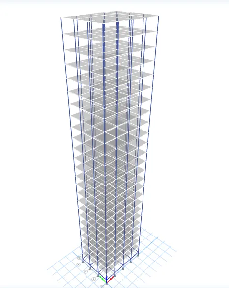
Select the assignment and click the select pinned supports link.
Attach the pin supports to the base.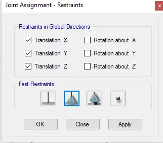
Define load patterns:
Click the define tab and click load patterns.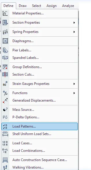
Define loads like dead load, live load, brick wall, earthquake load in x direction and positive x and negative x and same load also in Y direction. Give IS code of applicable loads.
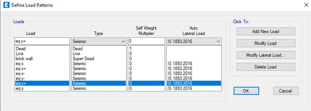
Click Modify Lateral Load, Set the Range from Base to 25th Floor and Seismic Zone as IV, Importance Factor as 1.25 and Time Period as 0.5s.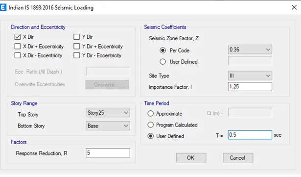
Do the same for all earthquake loads.
Allocation of loads:
Select similar stories.
Click on the shell load under the assignment tab.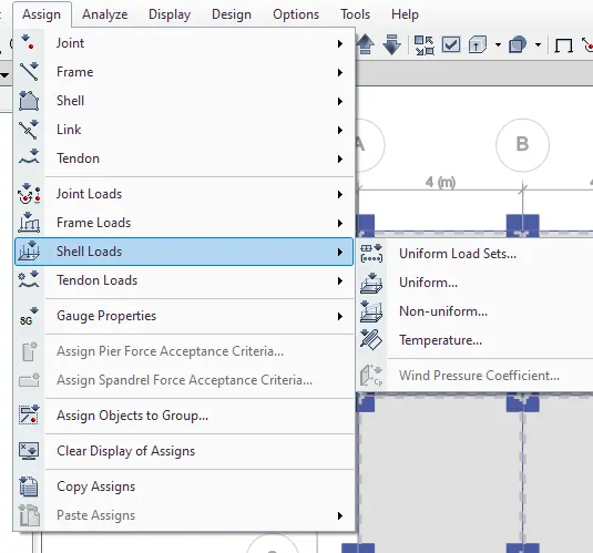
Click on live load and enter the value as 3Kn/m^2.
Click apply.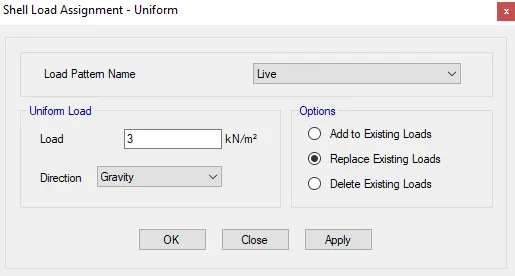
For the roof, we will only take 50% of the live load.
In the same way, we have to add a useful load of 10 Kn/m^2 to all beams.
Photo that selects all beams from the select-object type beams.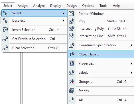
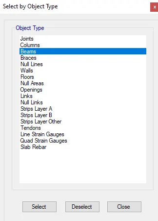
Go to Frame Load and click on Distributed Load and enter the value as 10 Kn/m^2.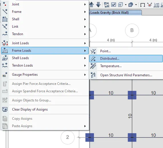
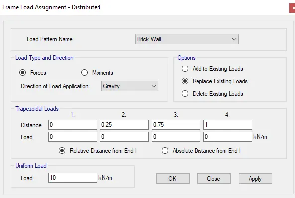
Go to the mass source on the Definitions tab.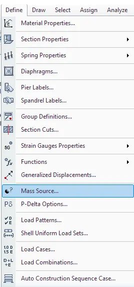
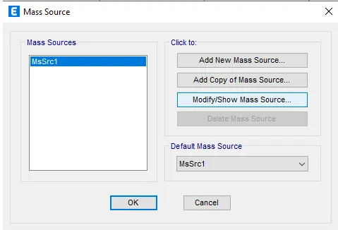
Edit the mass source and check the desired load.
Add load patterns assigned to the model.
Define load cases:
Click on load combinations.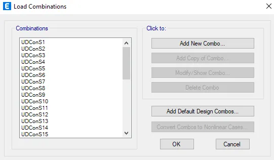
Click on add default design combinations.
Creating a diaphragm:
Earthquake loads act on the centriod of the building, so we need to add a diaphragm .
Go to Assign, click shell, click diaphragm .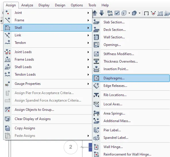
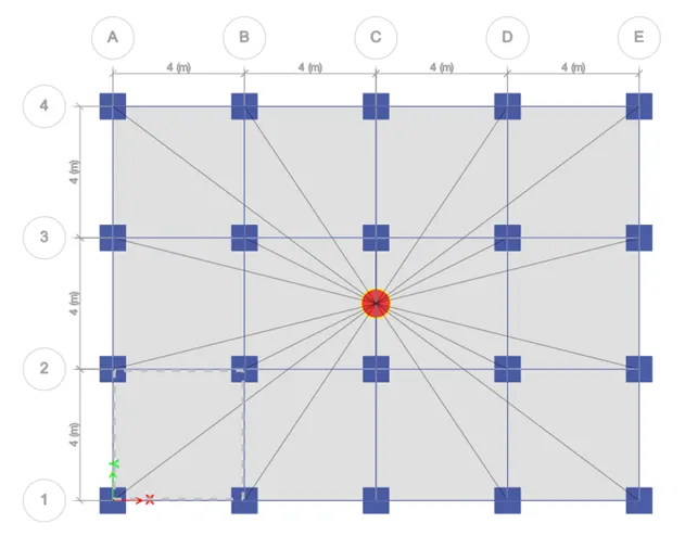
Click ok.
Click on the analysis tab to review the model.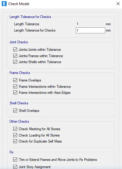
Click ok.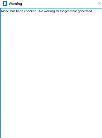
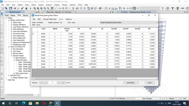
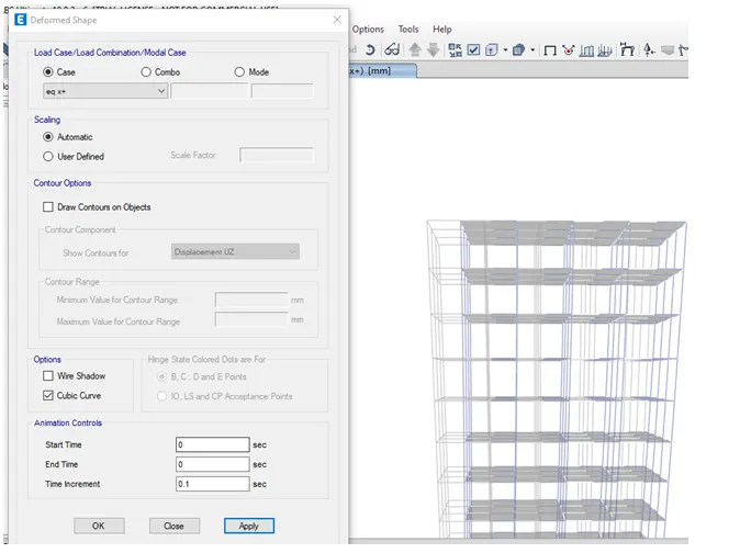
Run the analysis or click F5.
Result:
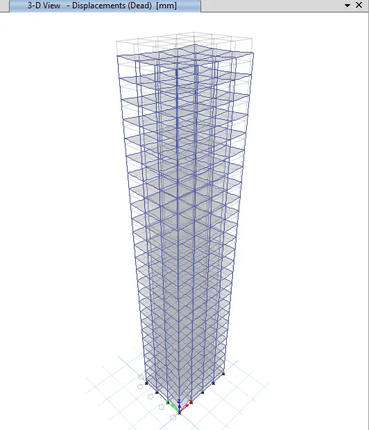
 \
\