Creating Bar Bending schedule, Different Door types, and Creation of standard drawing templates using AutoCad
Aim: Create:
Template, inserting text and attributes
Warehouse doors and their placement in blocks
Electric legend and its block production
Different types of doors for a housing project
Drawing bars, creating a block and creating a table as a plan for bending bars.
Commands used:
Block.
Insert.
Attributes.
Field.
Rectangle.
Line
Text.
Field.
Mirror.
Copy.
Offset.
1)
Objective: Creating templates, inserting text and attributes
Custom 1_ corner stamp
Custom 2_ corner stamp
Method:
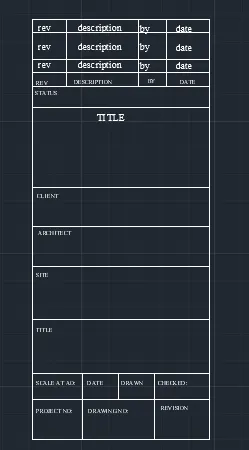
Custom 1_ corner stamp:
Create a rectangle measuring 66.63mm by 158mm
Divide it into columns using a line for the text box
Use an offset of 5,10,5,5,8,30,15,15,20,20,10,
For multi-line text, enter rev, description, by, date on first line by text height 2.5 and style - Times New Roman.
As it repeats in the next two lines, take the array, put the column as 1, the rows as 3, the spaces between the rows as 7.
Again, use multi-line text and enter the text you want in capital letters with a text height of 1.5 and a style like Times New Romans.
Creating a block:
Command "B" - block definition dialog will appear - name as "Custom1_ corner stamp" - select selection point and select point in table - select object - select entire table including text. Enter the scale uniformly and check enable spread .Choose the convert to block option.
As we selected to preserve the object, it will be preserved and the same as the actual drawing, and a block will be created for the objects we selected. If we want to use the go to insert block, select the object and insert it.
Custom 2_ corner stamp:
Draw a rectangle of 252 and 46 mm. Divide with lines into the desired rows and columns.
Using multiline text, insert the following: height 2.5.
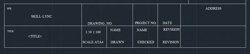
Create a small rectangle in the right corner, expand it, create rows and columns.
Use the attributes to create the text in it. The "ATT" - attribute definition dialog box will appear.
Insert tag line - the tag we give, visible before the block is created.
Prompt: Question, we need to add what we need to enter
Default: the value shown in the drawing after it has been created as a block.
Eg: In the first line of the 1st column "C" is the text to be displayed. command "ATT"
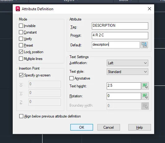
Place the tag line where we need to hear the 1st row 1st column of the created frame. Similarly, create attributes for the rest of the text. The attributes created are:
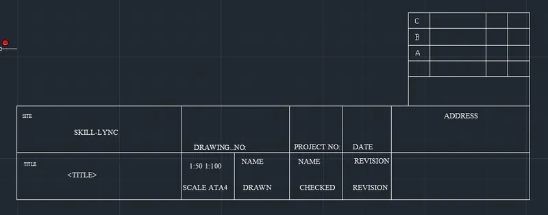
Now create a "B" block command called Custom2_titleblock, select the entire corner stamp and create it as a block. After creating it as a block, we can see that all the attributes are changed to their default values.
Result:
i) Custom_1 corner stamp is created
ii) Custom2_tiltleblock is created
2).
Objective: Create doors for the warehouse and place them in blocks:
Door 1 - 2330 x 2750 mm
Door 2 - 2330 x2750 mm
Method:
Door 1 -2330x2750mm:
Create a rectangle measuring 2330 x 2750 mm.
Offset 50 mm as a frame. 90 mm for the left side. Unfold the rectangle.
Split the "DIV" to split the top line into 4 segments. From the dividing point, draw lines vertically to divide it into shutters.
Offset 25mm on both sides for thickness, remove center line.
Create a rectangle to display the panels. 20 mm offset from the 1st rectangle and 100 mm offset from the 2nd rectangle. Draw lines connecting the corners of the outer and inner rectangles.
Create the panel as a block so it can be copied easily. Create a lock with the rectangle command and round the corners with a radius of 5 mm.
Copy copies all images.
A layer is created and all objects are stored in different layers.
Creating a block:
Command "B" - name door 1 - select point - select corner point - select object - select entire object - ok. Select the scale to be uniform and enable decomposition.
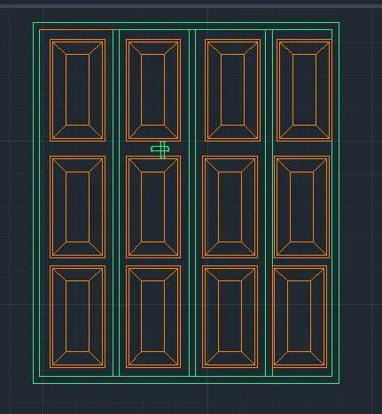
Door 2 -2330 x 2750 mm:
Create a rectangle measuring 2330x2750mm. Offset 50mm as a frame. 90 mm for the left side. Unfold the rectangle.
Split the "DIV" to split the top line into 4 segments. From the dividing point, draw lines vertically and divide them into caps. To make the points visible, select the command "DDPTYPE" point style
Offset 25mm on both sides for thickness, delete the center line. Create a lock by drawing a rectangle on opposite sides and rounding the corners with a radius of 5 mm.
Create layers and insert lock, frame in different layers
Create it as a "B" block - select a corner point - select the entire door - check the scale box evenly - spread out.
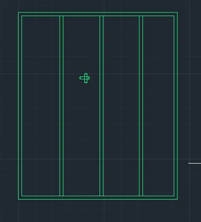
Result: The door block has been created and the doors are created.
3).
Objective: Create an electric legend
Create each electrical symbol
Create them as a block
The arrangement is in the legends
Method:
Creating electrical symbols
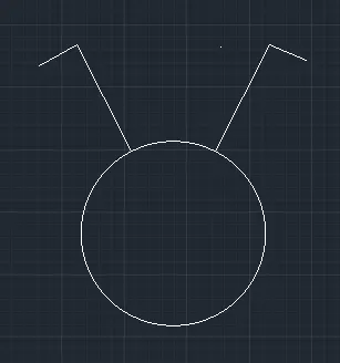
Simple switch: Draw a circle with a radius of 64mm and use a line to draw a slanted vertical line and a horizontal line perpendicular to the slanted as needed.
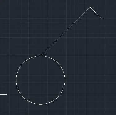
Double Group Switch: Draw a circle and draw two horizontal lines and a vertical slope line.
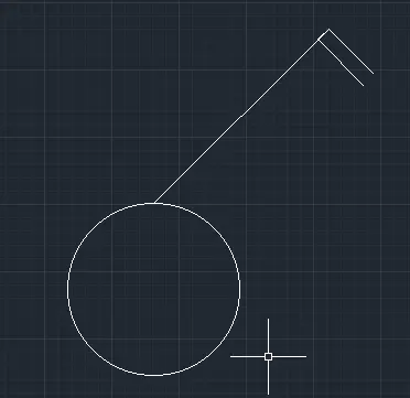
Triple Group Switch: Draw a circle, 1 vertical slanted line and three horizontal lines.
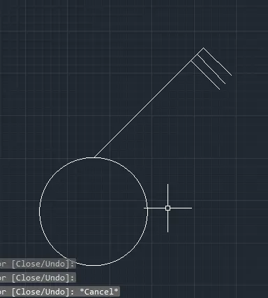
Single two-way switch: Draw the same as a single gang switch and use the donut command to enter the inner diameter as zero and for the outer diameter select it in a circle.
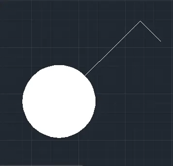
Double Two-Way Switch: Draw the same as the double switch to create a donut.
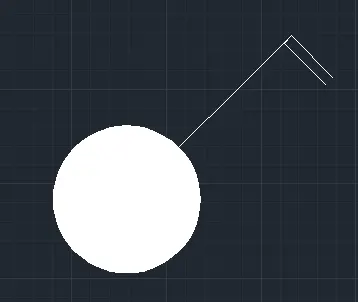
Triple Two-Way Switch: Draw the same as the triple switch to create a donut.
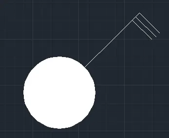
Switch cross: Create a circle and a ring inside and use the line command to draw an inclined vertical and perpendicular horizontal plane. Mirror the line in both directions.
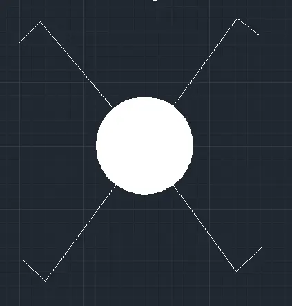
Switch series: Copy the switch cross and remove the bottom two lines, also remove the ring.
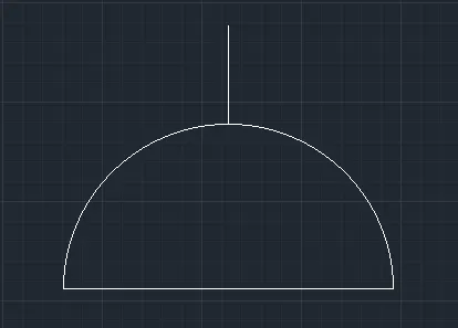
Simple socket: Create a circle, divide it in half and draw a line at the top.
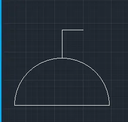
One socket for the lamp: From one socket, draw a horizontal line perpendicular to the vertical.
Double scoket: Draw a single foot and copy it to create it and place it by snapping.
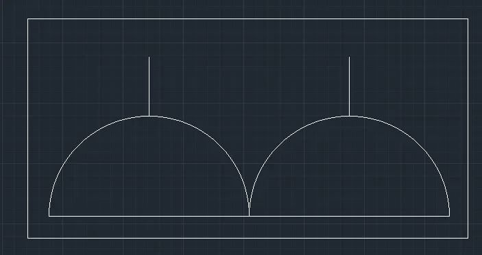
Floor socket single: Draw a rectangle surrounding one socket.
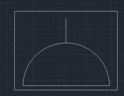
Floor single Socket for lamp: Draw a rectangle surrounding one lamp socket
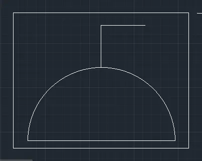
Floor socket double : Create two separate drawers and place a rectangle around them.
Floor socket simple telephone: Draw one socket, a triangle and surrounded by a rectangle.
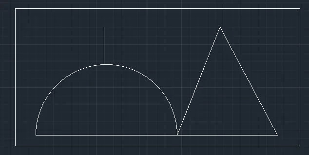
Double floor socket, telephone: draw 2 single sockets and a triangle surrounded by a rectangle.
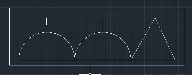
Telephone socket: Draw a triangle
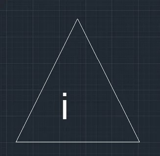
Internet socket: Insert the text "i" in the triangle.
TV socket: Insert the text "TV" in the triangle.

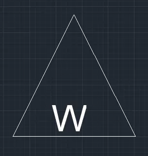
Weatherproof socket: Insert the text "w" in the triangle.
Bottom of the pipe: Draw a rectangle - select the bottom grip point - select add vertex - then pull the vertex to create a bend, using the line to draw lines.
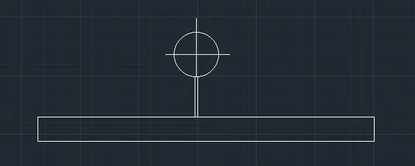
Wall mount: Draw a base using a rectangle, create a circle, draw a line connecting the rectangle and the circle, draw a cross line inside the circle.
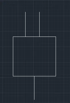
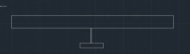
Picture lamp: draw two rectangles connected by a line.
Create them as a block:
Name command "B" single group switch - select point - select object (single group switch created) - check scale evenly and enable exploding options.
Similarly, define each of them as a block with the appropriate names. Do the same for the remaining symbols.
Creating and arranging a border in layers:
First, create a rectangular table with 10 rows and 6 columns.
Place each of the blocks in the appropriate rows and columns.
To enter text using a block from the insert tab - select a field - select an object - select a block.
Eg: for a single gang switch - select from the box. - select uppercase letters in the format.
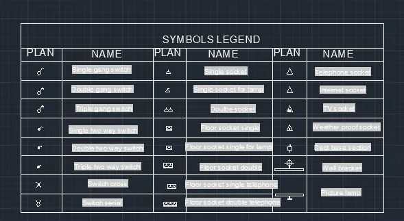
Place the text in the appropriate lines and set the text height to 150. Similarly, place all the headings in the legends.
Result:switches are drawn and blocked in table
4)
Objective: Draw the door of a residential project and create it as a block.
D1
D2
D3
D4
D5
D6
Method:
1). D1 - 2.10" x 6.11":
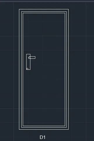
Draw a rectangle measuring 2'10" and 6'11". Draw an offset of 1.5" for the frame. Draw an offset of 1" for the shutter.
Draw a lock with two perpendicular rectangles and round the corners with a 0.1" radius and a circle. Write the text with multiline text "D1".
Create it as block "B" - name it as "type-D1" - select a corner point - select an object. then a block is created.
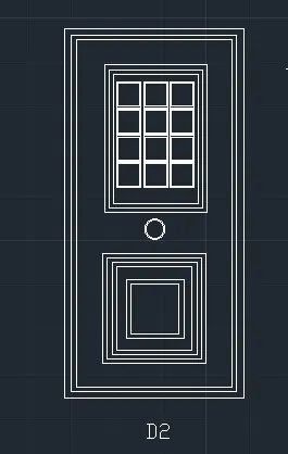
2). D2 - 3.4" x 6.11":
Draw a rectangle measuring 3'4" and 6'11". Draw an offset of 1.5" for the frame. Draw an offset of 1" for the shutter.
Draw a rectangle for the 1'11" and 2'9.1" panel, then indent 1" twice. Draw a 5.4" x 5.7" rectangle, indenting 0.3".
Copy it with copy "co" command - select mode - select rectangle - select field - enter field number as 3 - position it as needed. Copy the 3 rectangles into 4 rows.
For the second panel, draw a 1'11" x 2'0.6" rectangle. Indent 1" 3 times Draw another rectangle inside this rectangle measuring 1'0.8" x 1' 1.2" and indenting 1".
Draw a lock along the circle between the two panels. Type the text with multiline text "D2".
Create it as a block "B"- name it as "type-D2" -select a corner point- select an object, then the block will be created.
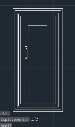
3). D3 -2.9" x 6.11":
Draw a 2.9" x 6.11" rectangle.
1" offset for thickness, 2" offset for frame, 1" thickness. 1.5" offset for cap thickness.
At the top, draw a 1'3" x 9.3" ventilation rectangle, give the thickness an offset of 1". Hatch inside the rectangle.
Create a lock with a rectangle, two of them, perpendicular to each other and a circle.
Create it as a block Command "B" - enter name as type d3 -select point- select object -check uniform scale and spread everything.
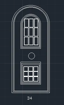
4). D4 - 3.9" x 8.7":
Draw a 3'9" x 6'10" rectangle "REC". Unfold it and create an arc using the 2-point method with both points as endpoints. Offset the arc and line by 1.5" and then by 1".
Offset 8" from the arch and rectangle for the panel and split it in two. Make 2 x 1" offsets to show the thickness in the top image and the bottom rectangle. Create rectangles inside the panel.
Create a circle for the lock.
Make it a block, name it type D4 - select a point and select an object, check the uniform scale dialog and lay it all out.
5). D5 - 3.5" x 6.8":
Draw a 3'5" x 6'8" rectangle. Indent 1.5" for the frame. Indent 1" as the thickness of the cap. Create another rectangle inside with an indent of 4.4".
Create another rectangle on the bottom 2'2.9" x 2'2.6". Indent 1" twice for both rectangles.
Create a rectangle inside for the panels with an indent of 0.5". Copy it for 3 columns and 4 rows. Similarly, copy it to the bottom rectangle for 3 rows and 3 columns.
Create it as a block Command "B" - name as type D5 - select point - select object - check scale evenly and spread everything out.
6). D6 - 3.5" x 7" 11.6":
Draw a 3'5" x 7'11.6" rectangle "REC". Unfold it and create an arc using the 2-point method with both points as endpoints. Offset the arc and line by 1.5" and then 1" for the frame.
Offset 8" from the arch and rectangle for the panel and split it in two. Make 2 times the 1" offset to show the thickness in the top image and the bottom rectangle. Create rectangles inside the top panel, 3 rows and 4 columns.
For the bottom panel, offset the rectangles by 1" 3 times as and 3.3" and 1" again. Create a circle for the lock.
Make it a block, name it type D6 - select a point and select an object, check the uniform scale dialog and lay everything out.
Result: The door is created and blocks are created from it.
5)
Objective: Create a bar bending plan and insert it as a block.
Drawing each shape.
Create it as a block.
Inserting into the table as a bending plan of the member.
Method:
1) Drawing each shape:
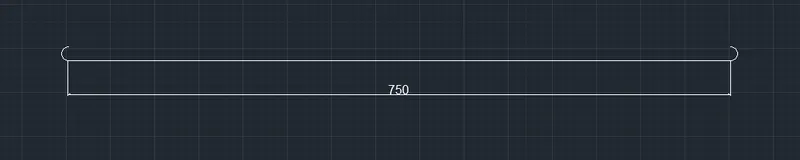
A-20mm:
Draw a 750 cm line for a straight bar. Create an arc for the bend. Create on one side and mirror on the other side.
B-16mm:
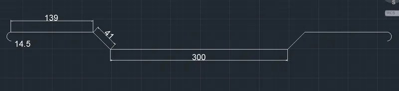
Draw a 300mm line for a straight bar. Draw a vertical line 41 cm and extend the horizontal line and draw a line inclined at an angle of 45 degrees from the base of the vertical line to the horizontal line.
Cut the unnecessary lines. Copy the same to the other side. Draw a horizontal line of 139 cm and copy it to the other side.
C -16mm:
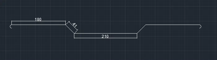
Draw a line 210 cm. Draw a vertical line 41 cm and extend the horizontal line and draw a line inclined at an angle of 45 degrees from the base of the vertical line to the horizontal line.
Cut out the unwanted lines. Copy the same to the other side. Draw a horizontal line of 180 cm and copy it to the other side. Draw a bend in an arc and mirror the same on the other side.
D-12mm:
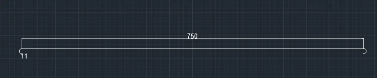
Draw a 750 cm line for a straight bar. Draw an arc down. Mirror it to the other side.
E-10mm:
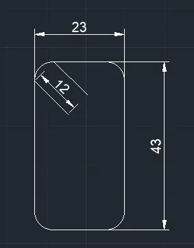
Draw a rectangle 23 cm and 43 cm. Corner rounding with a rounding radius of 5 cm. Draw two lines 120 cm.
Creating each one as a block with command -"B'- name as A - select point - select object - select delete - check the scale uniformly box and spread everything out.
Similarly, create 5 blocks: A,B,C,D,E and insert each of the rods as blocks.
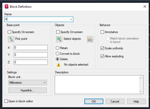
Inserting blocks into a table:
Create a table with a rectangle and divide it into 6 rows and 7 columns. For multi-line text, enter type, shape size, length, no, total length, unit weight, total weight, and any other text. Use the "I" command to insert each of the blocks in the appropriate columns.
Result:
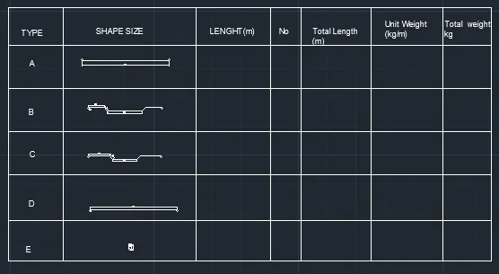
RESULT:
The template is drawn and text and attributes are inserted.
Warehouse doors are drawn and placed in blocks.
An electric legend will be created and blocks will be created from it
Different types of doors for the housing project are drawn and placed in blocks
The members are drawn and made as blocks and inserted into the table as a member bending plan.