Modelling of 25 storey building with the specified properties using ETABS
AIM: Model a 25 storey building on ETABS with structural properties as specified below. Ground floor or plinth floor level can be taken at a height of 1.5 metres from the base. Each of the successive 25 storeys has a storey height of 3 metres.
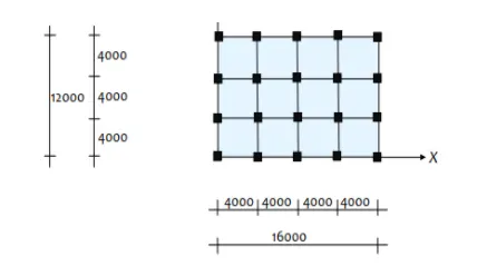
Structural Element Sizes
- Beams : 300 × 400 mm
- Columns : 800 × 800 mm
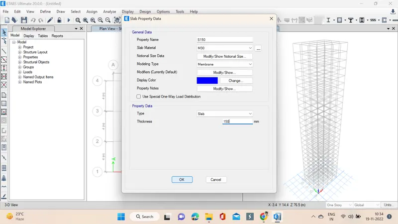
- Slab : 150 mm thick
Material Properties
- Grade of Concrete : M30
- Grade of Steel Reinforcement Bars : Fe 415
Loading
- Dead Load on beams from infill wall : 10 kN/m (Let us assume the same for roof floor in view of parapet)
- Live load on floor : 3 kN/m2 (Let us assume the same for roof floor)
a) Buildings are assumed to be pinned at the base
b) All columns in all storey are of the same size
c) All beams in all storeys are of the same size
d) Building is located on Soil type-II and in Zone-III. Assume other factors if required.
INTRODUCTION: ETABS is an engineering software product that caters to multi-story building analysis and design. Modeling tools and templates, code-based load prescriptions, analysis methods and solution techniques, all coordinate with the grid-like geometry unique to this class of structure.
PROCEDURE:
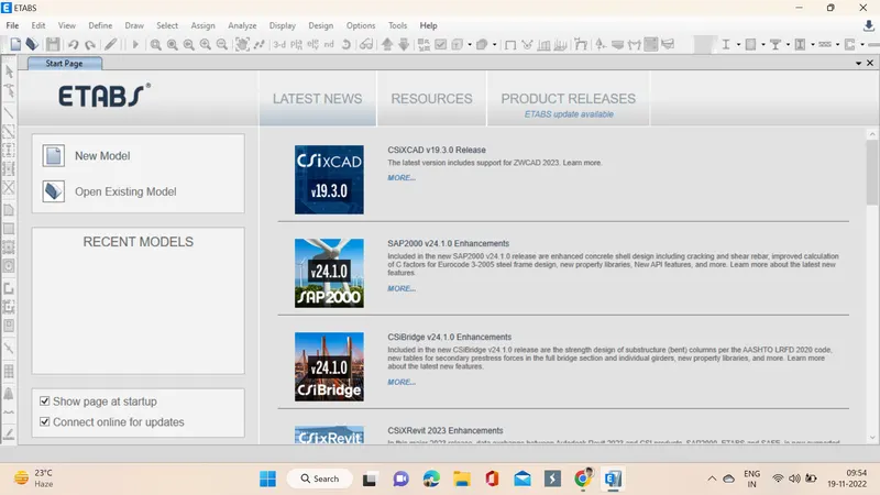
1. Open the ETABS softwar by double click on that icon, sofware interface opens as shown below.
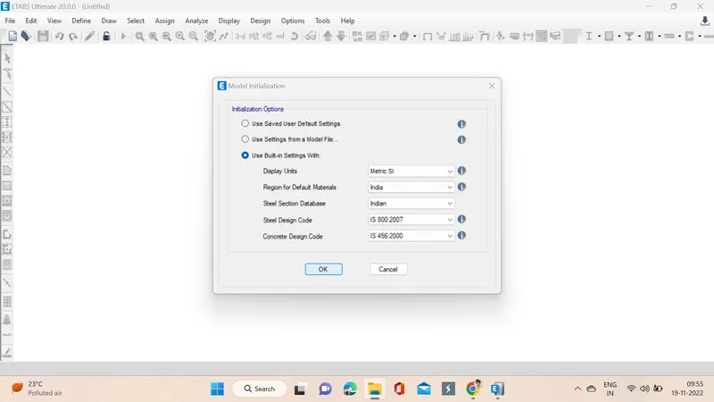
2. The very next step is to assign settings like codes used and units, then ok is clicked.
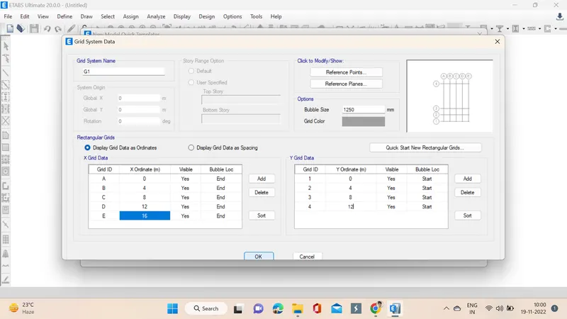
3. Now another tab pops up in which custom gird spacing is selected and edit grid data is opened.
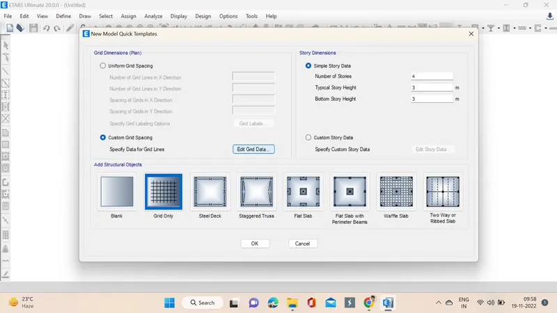
4. The x ordinate one more is added and the necessary changes are made even in y ordinate.
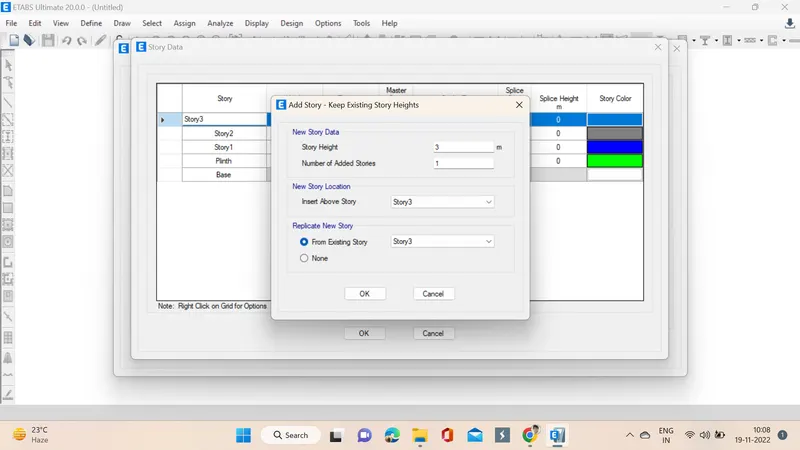
5. Next step we click on edit story data and then we change story 1 as plinth and then we specify the plinth height as 1.5 and change the names of stories accordingly, next we right click to add the next stories as assigment is of 25 we select 22 more in no of stories to be added since already 3 stories are present.
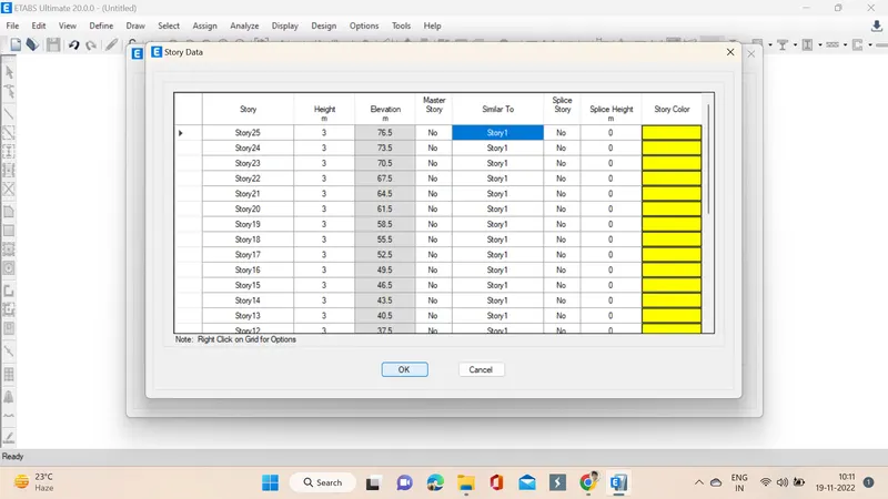
6. All the stories are added now they are added as similar to story1, then ok is clicked.
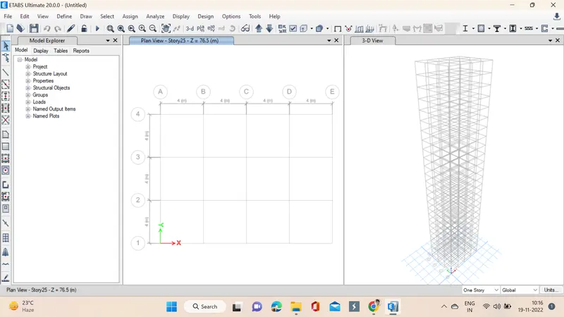
7. After the ok is clicked three tabs appear on the screen showing model explorer, plan view and 3-D view of the assigned stories.
8. Go to define materials option, select material properties, in that concrete of M30 and reinforcement of 415 are added.
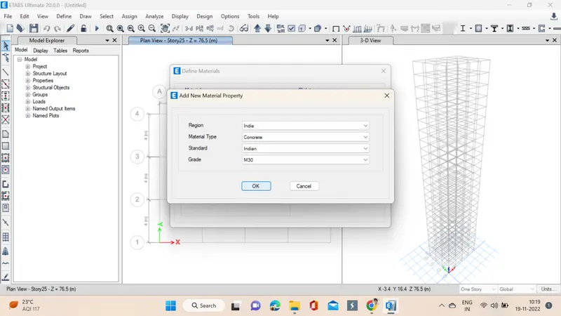
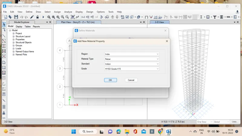
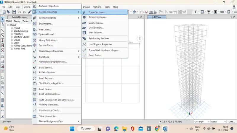
9. We need assign beams, columns, slabs for that go to define option select frame sections.
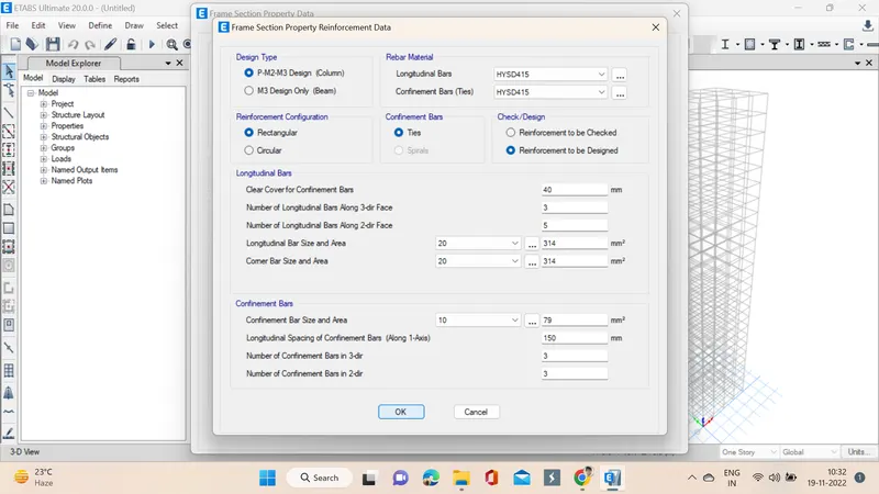
10. Beams as per the schedule is titled and dimensions are also specified, in the section properties beam is selected and material is given as M30 as assigned before and for rebar HYSD 415 is specified.
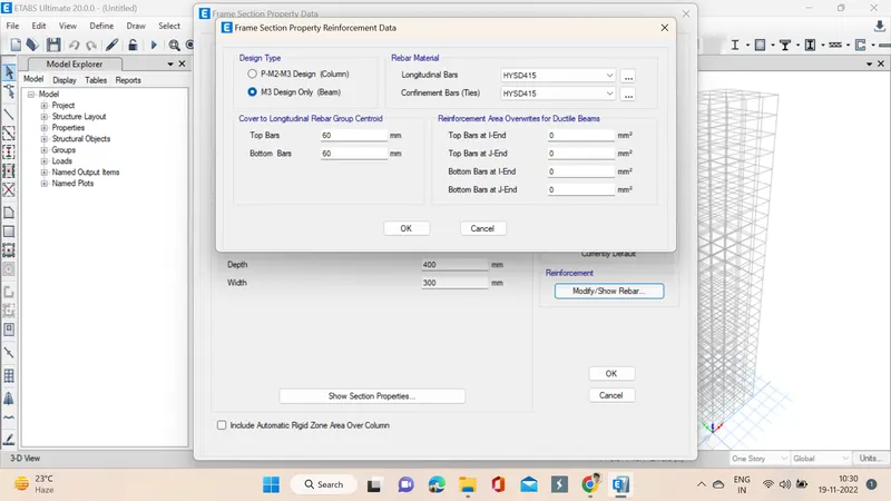
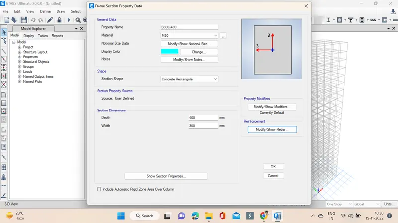
11. The process is same for columns assigning materials and dimensiopns but section properties column is selected that is the only change.
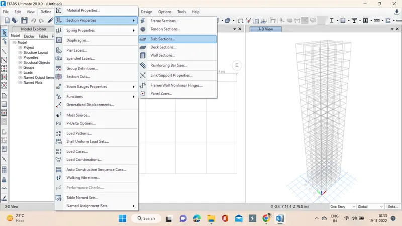
12. Next step we go through the define material and then select slab sections a window pops up in which we specify the properties of the slab and it is attached to the membrane.
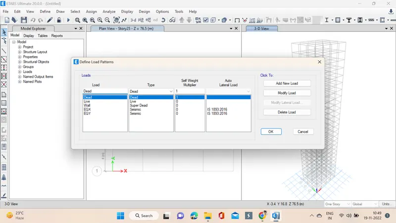
13. We assign loads in the following step from define option we select load patterns, as dead live were present additional loads are added.
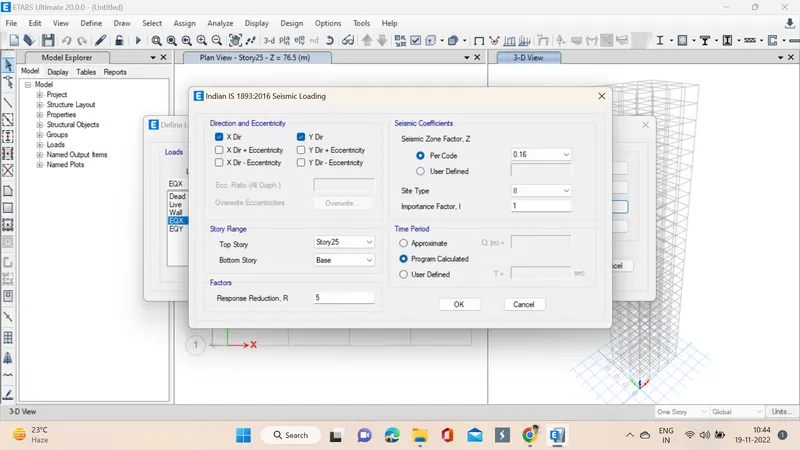
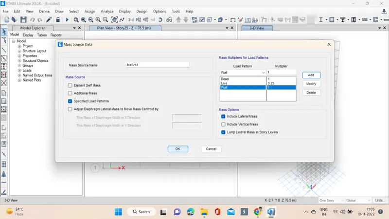
14. Now mass source is added by selecting mass source from define option, loads and values are specified and then ok is clicked to add.
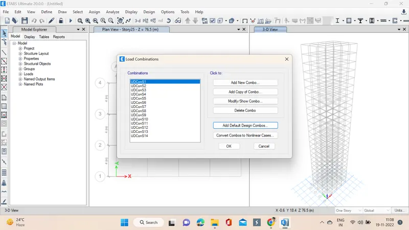
15. Now load cases are added or not checked by clicking on load cases, next load combinations are specified by selecting frame design user defined in load combinations.
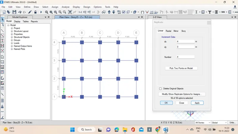
16. Now by selecting quick column and properties of specified column the columns are placed but we need to make sure the all stories option is selected. We can see the columns are specifed in all the stories, as we opted all stories option in the bottom right side. Next we use replicate option to simply replicate all the columns as first to save time.
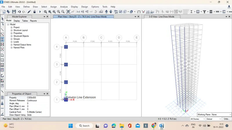
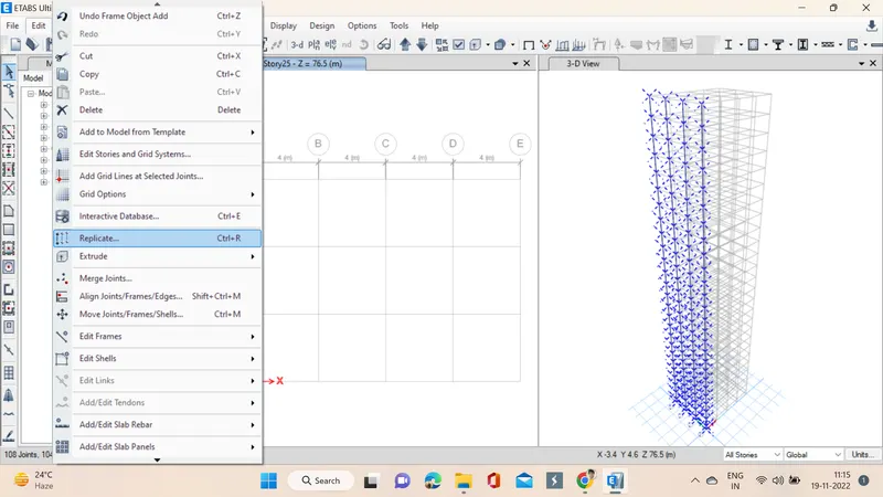
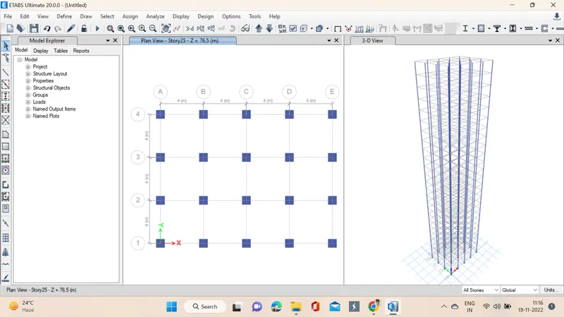
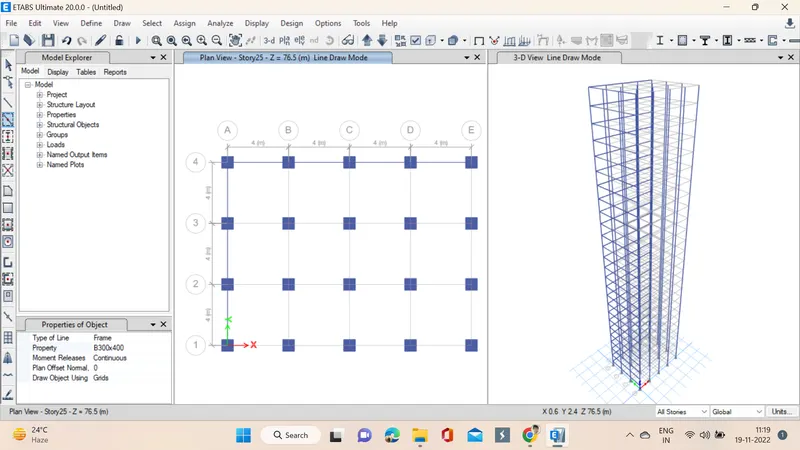
17. Now by selecting quick beams and properties of specified beams the beams are placed but we need to make sure the all stories option is selected. We can see the beams are specifed in all the stories, as we opted all stories option in the bottom right side. Next we use replicate option to simply replicate all the columns as first to save time.
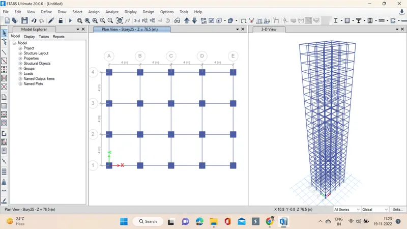
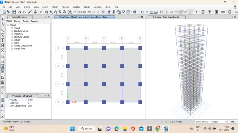
18. Now the slabs are placed by selecting quick draw slab, we need to select the specified slab and then drop them in the stories, before this we need to go to story1 from plan option and then select story1 after that we need to go to the similar stories option as we dont want slab at our plinth level.
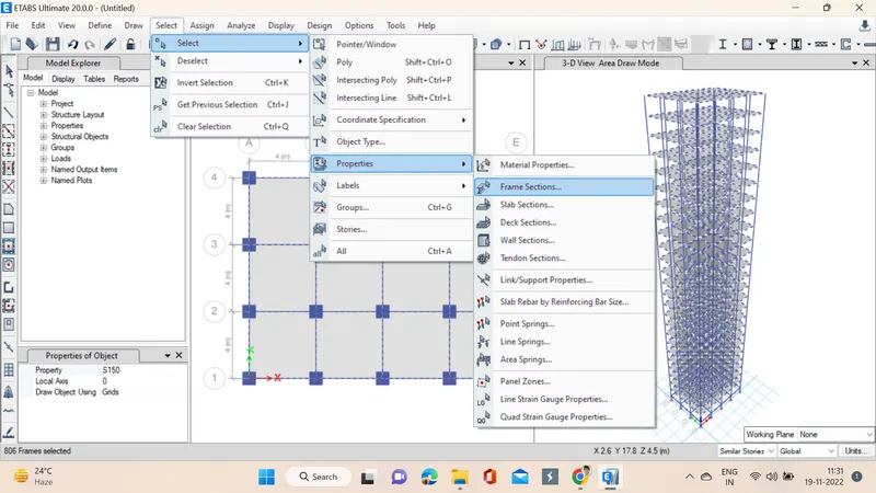
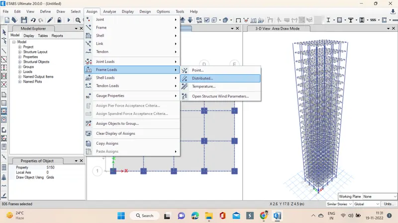
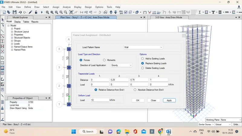
19. Now we will apply loads, for that first we select the beams from select option -> properties -> frame sections, after selecting the beams now load is assigned by going into assign option assign -> frame loads -> distributed in the distributed a window pops up in which load pattern is given as wall, load as 10KN/m as per the assignment and apply and okay is clicked.
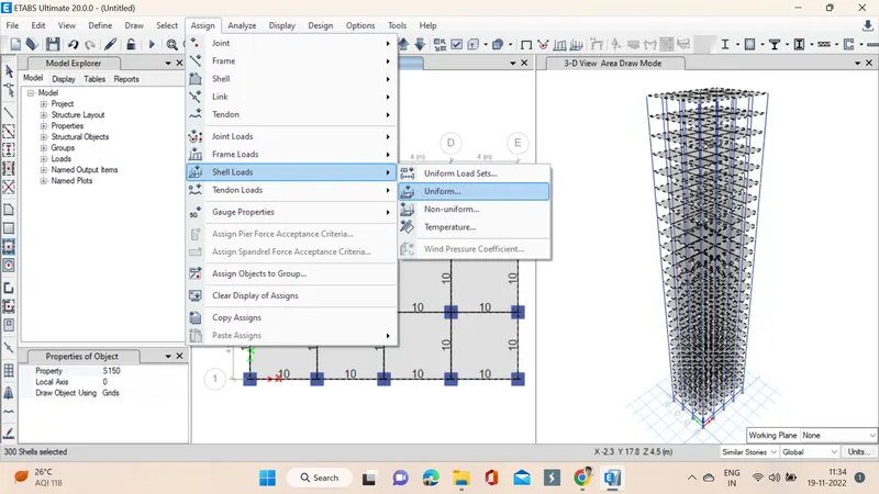
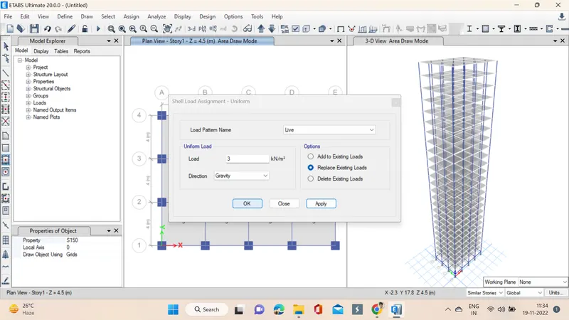
20. In the next step we select the slabs by same process now select option -> properties -> slab sections, after selecting the slabs now load is assigned by going into assign option assign -> shell loads -> uniform then a window pops up in which load pattern is given as live, load as 3KN/m^2 as per the assignment and apply and okay is clicked.
21. Again slabs are selected this time to assign diaphragms and then D1 is assigned so that the centre of mass will be calculated automatically.
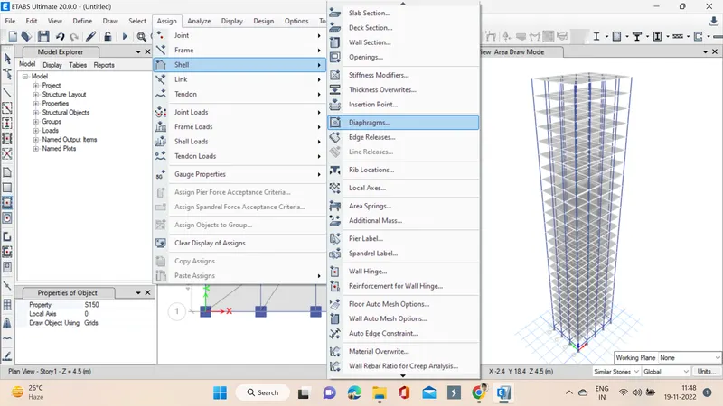
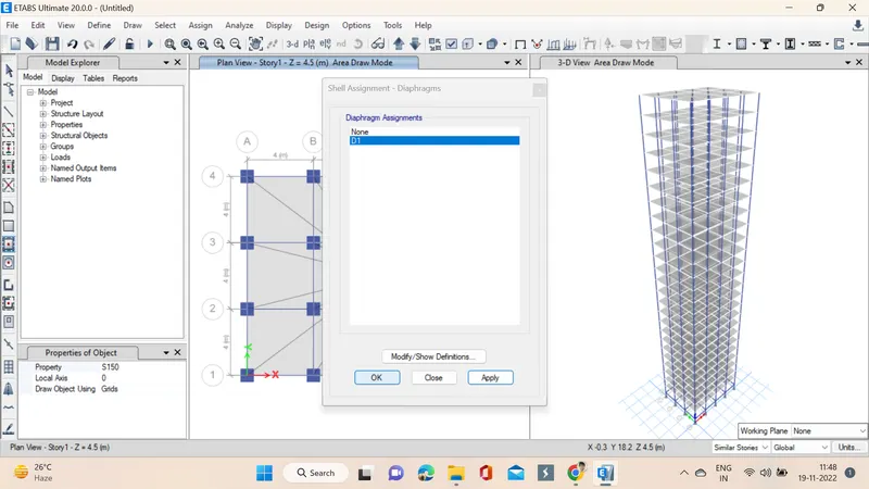
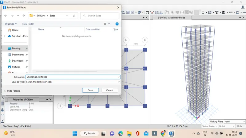
22. Now all the necessary things are done we run analysis on the building, to that we need to save the file we give a suitable name and the running is done as we can see the deflected shape of the building shows model analysis is done.
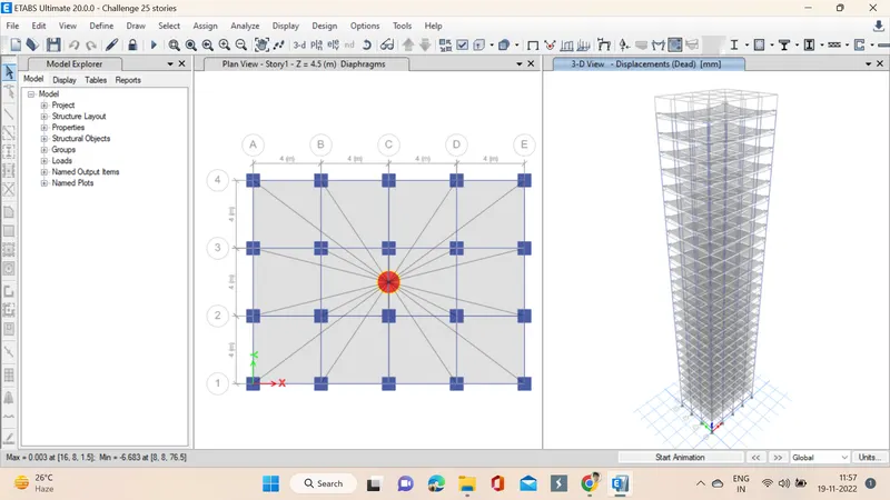
RESULT: A 25 story building using the ETABS software was drawn and the loads are also assigned and analysis is runned successfully. The following checks as specified in the assignment were also made.
- Check if the translational fundamental natural period of vibration in both the x and y direction is approximately: Tx1Tx1= 4.4 second Ty1Ty1= 4.2 second. This check will help confirm if modelling is done correctly. Some deviations from the above values is possible (± 2%). But any major deviation will suggest an error in modelling. We got 4.41 in x-direction and 4.22 in y-direction almost equal
- Check if the following provision in Table 5 of IS 1893 (part 1) – 2016, on torsional irregularity satisfied. The natural period corresponding to the torsional mode of oscillation must be less than the two fundamental translational modes of oscillation along each principal plan directions. Yes
- Check if the two provisions of clause 7 in Table 6 (shown below) of IS 1893 (part 1) – 2016, regarding vertical irregularity is satisfied.
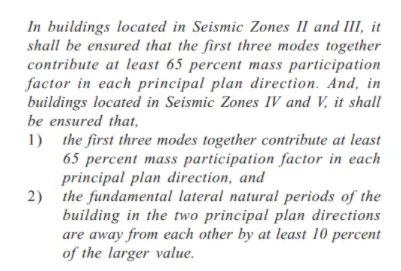 For first point Yes, For second point No
- Check if provision on inter-storey drift limitations in clause 7.11.1.1 satisfied. Please note that this check is for Serviceability Limit State and hence is for situation when stucture is subjected to unfactored seismic base shear
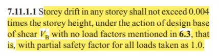 Yes we have achieved it.