Modelling of 25 storey building with the specified properties using ETABS
Aim: To model a 25 storey building on ETABS with structural properties.
Procedure:
- Open Etab software click on new model
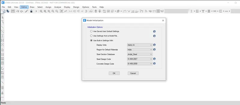
- Model intialization dialogue box appears enter the details in it, click on ok
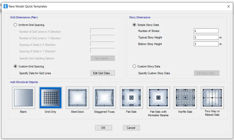
- From new model quick template select custom grid spacing and click in edit grid data
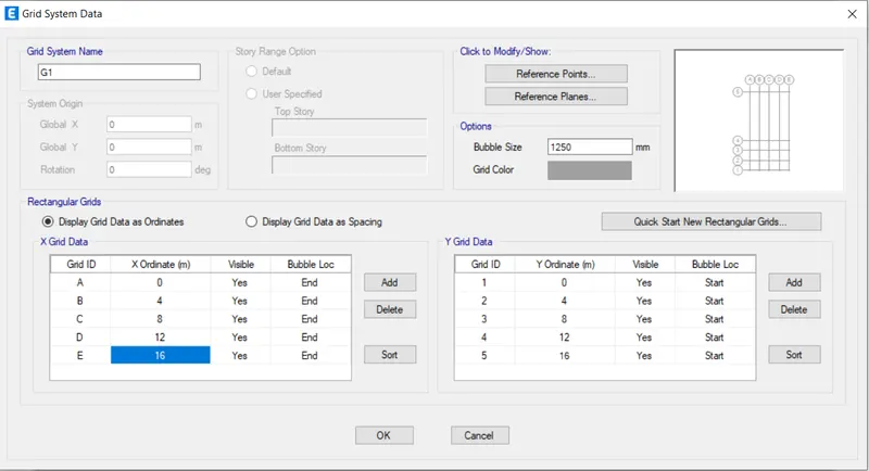
- Add number of grids as mentioned in the question and enter the details in it and click on ok.
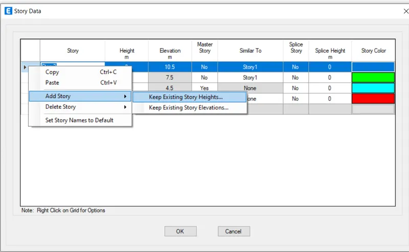
- Then click on custom storeydata and select edit storeydata
- Now in storeydata edit the storeyand height and all other necessary details
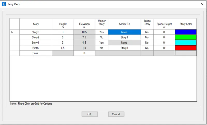
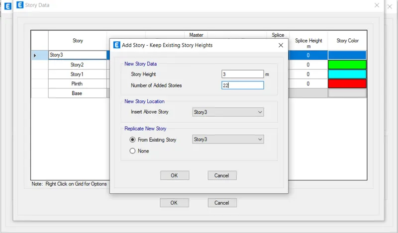
- Then select on add storeyand and click on keep existing storeyheight and add no of storeymentioned and click on ok
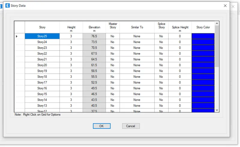
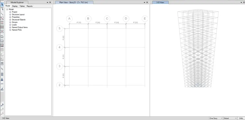
- Now 25 storeyhas been created above the plinth level
- Now to add material click on define and select material property
- And add concrete and steel material then click on ok
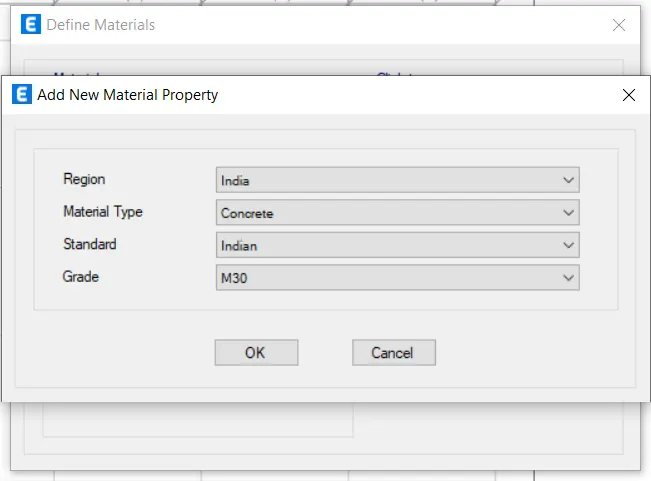
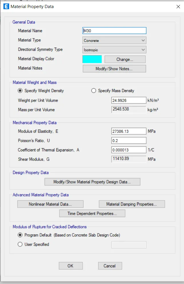
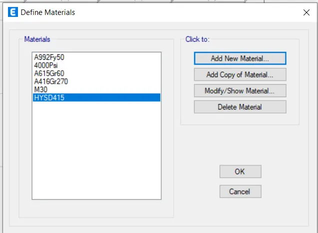
- To add beams and column, click on define select selection properties and select frame section
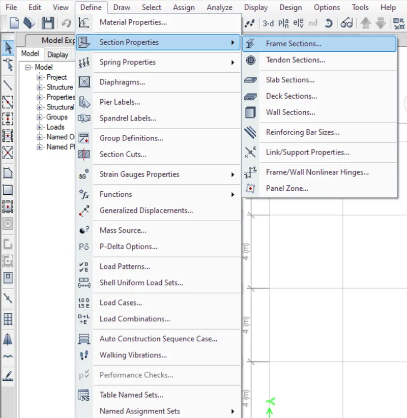
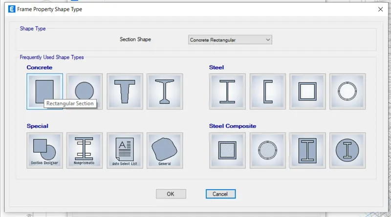
- To add beam, Select the shape from the frame property shape type
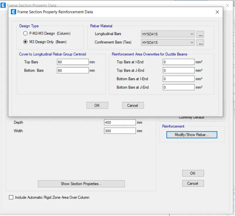
- Enter the beam details in the frame selection property data

- To enter the reinforcement details click on modify/show modifers and enter the beam steel details
- To add column, select on add new property in the frame properties
- Select the shape and add column details as given
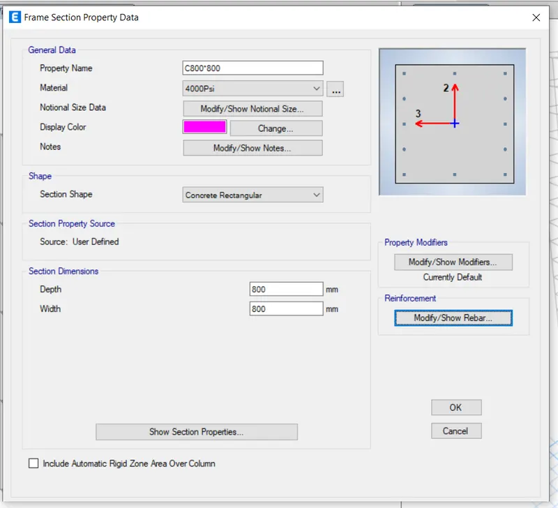
- To add reinforcement details click on modify and add the details and click on ok
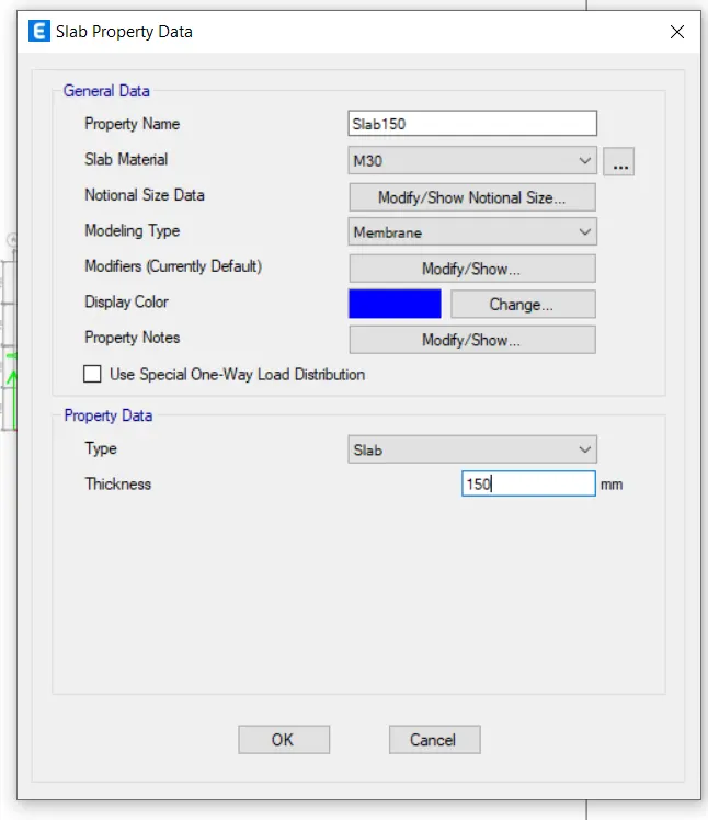
- To add slab go to define and select section properties and slab selection
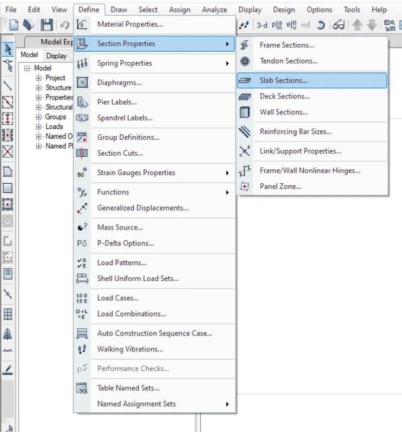
- Click on add new property and enter the details in slab property data
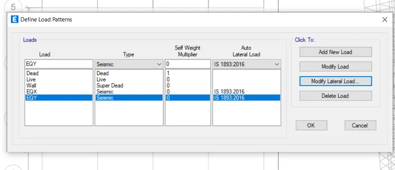
- To add load patterns click on define and selelct load patterns
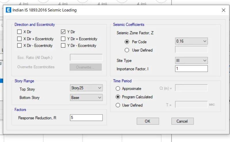
- Then in define load patterns enter the loads which is needed and modify them
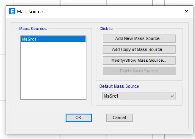
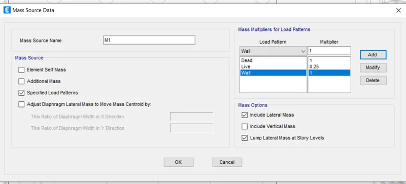
- To add mass, go to define and select mass source and enter the mass details in the mass source data
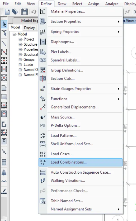
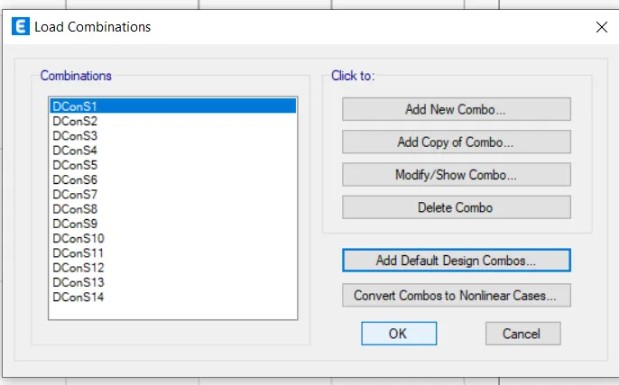
- To add load combinations go to define and click on load combinations
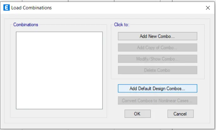
- Then a dialogue box appears in that select add default design combo and select
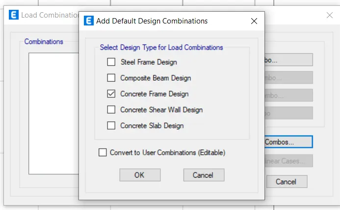
Then select concrete frame design and click on ok
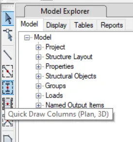
- To add created columns to the plan, select on quick draw columns icon which is present in the left side
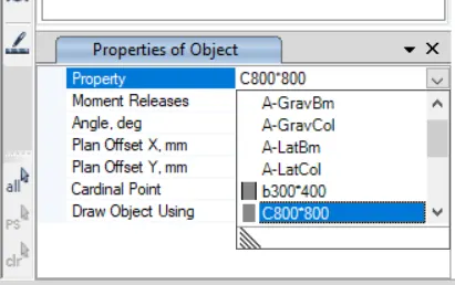
- Then in the properties option selelct the column which was created and place the columns on the grids wherever needed
- Select all storeyoption which is present in the bottom right side before placing the column
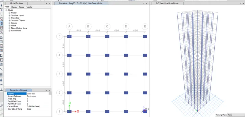
- To add beams which was created to the plan
- Click on quick draw beams and column, in the property box select the beam which was created
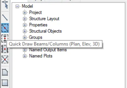
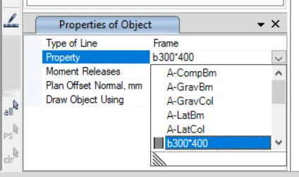
- Now place the mouse in between the column and selelct the grid the beam will be created
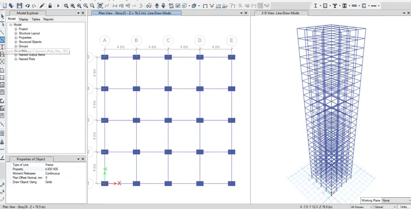
- To add the slab, change the storeyoption to similar storey
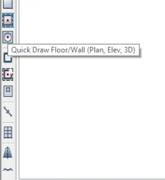
- Select the quick draw slab icon, from the property option select the slab which was created and add the slab
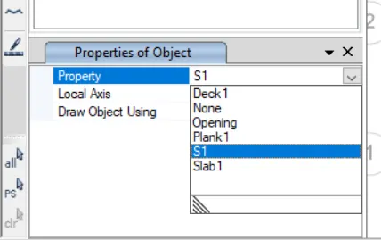
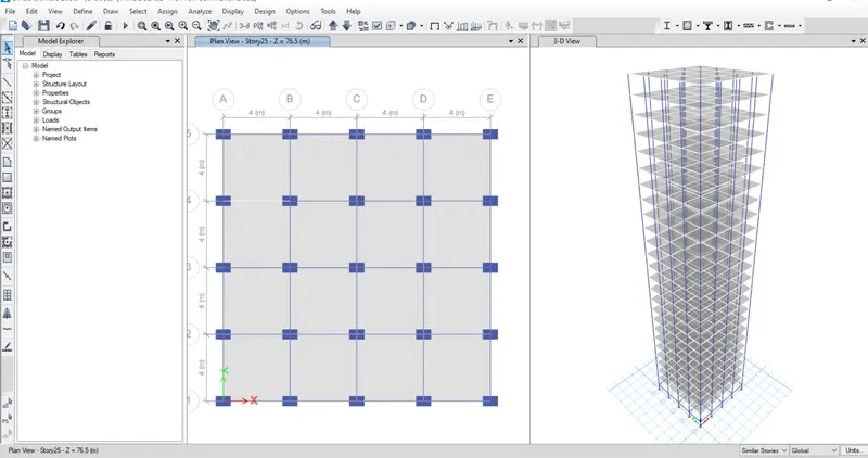
To assign the loads
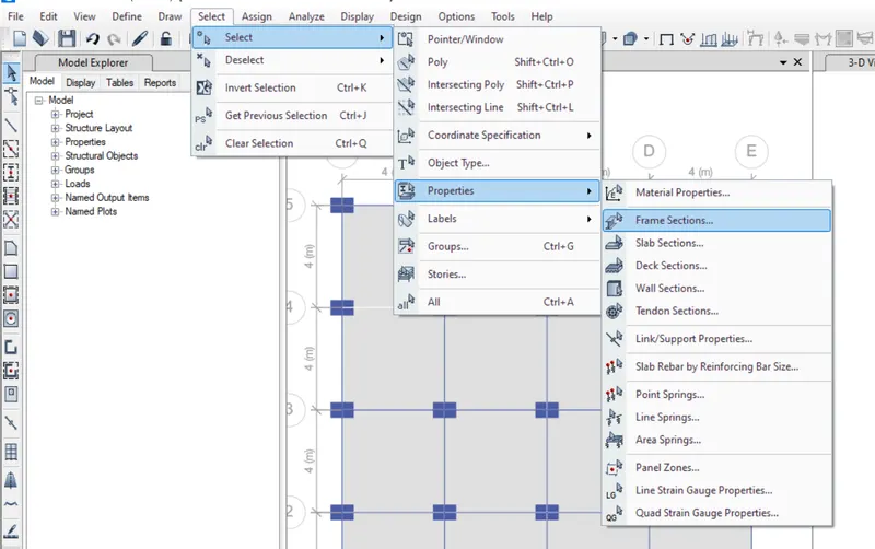
- Go to select option, click on frame selection and click on beam which was created
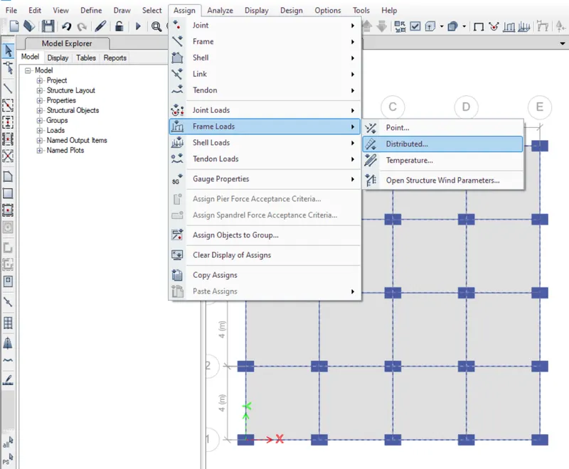
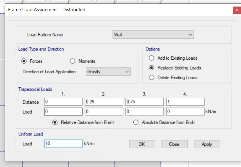
- To assign the load go to assign option and select frame load and then distributed and enter the load which is needed to apply and click on apply
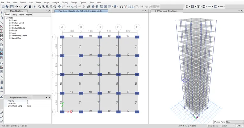
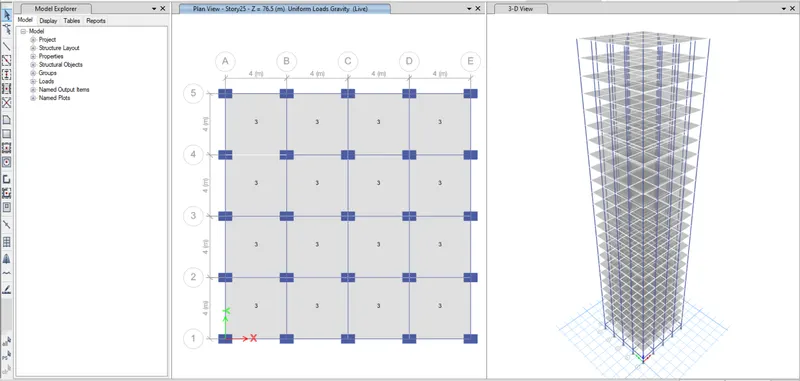
- To add the loads to the slab
- Go to select option and click on slab section
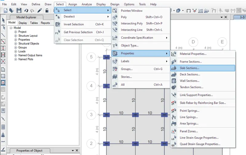
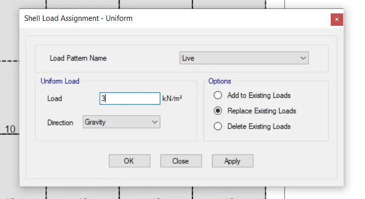
- To assign the loads to the slab, go to assign option and select shell load then select uniform
- Then enter the details of the load in the load assigments
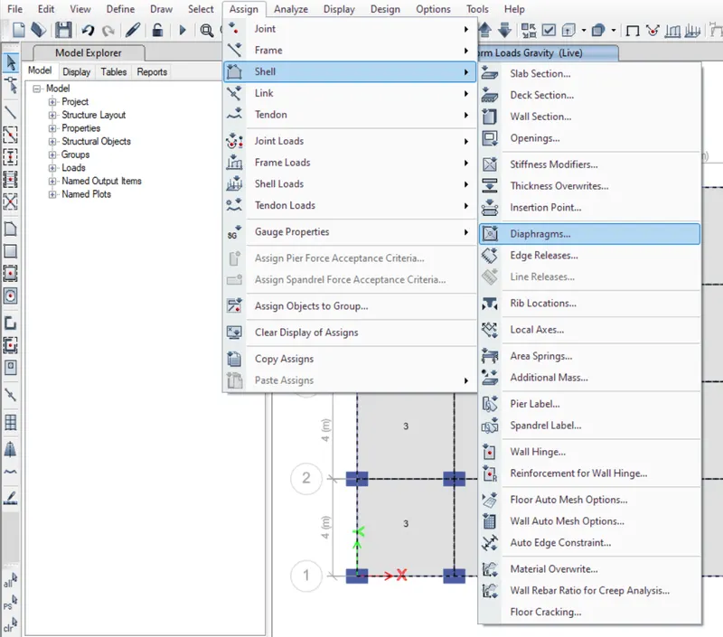
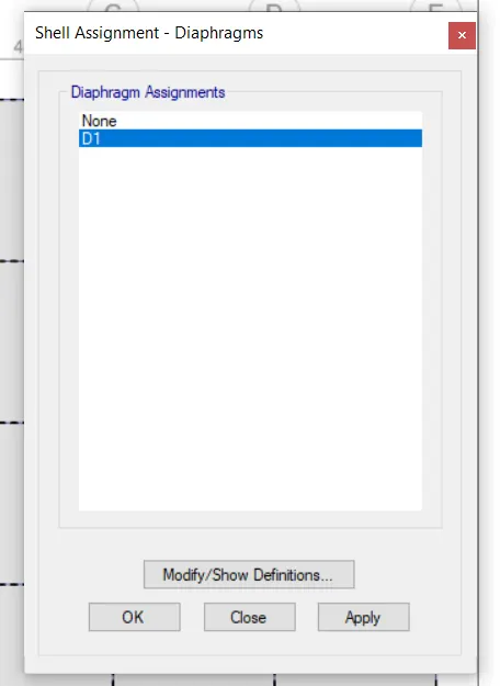
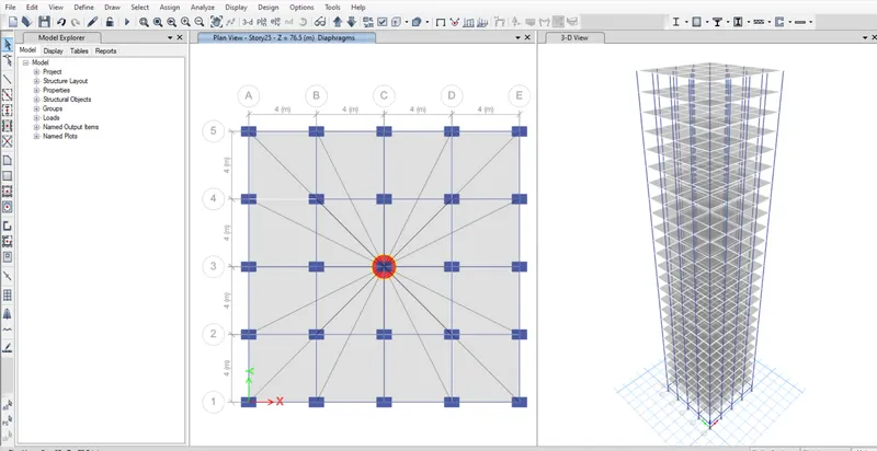
- To add the diaphram
- Go to the select option and select slab
- Then click on assign option, select shell and click on diaphram option
- After add every details and load click on analysis icon
- After that to see the result go to model explorer, select table, select analysis result, structure output and left click on the option and click on table
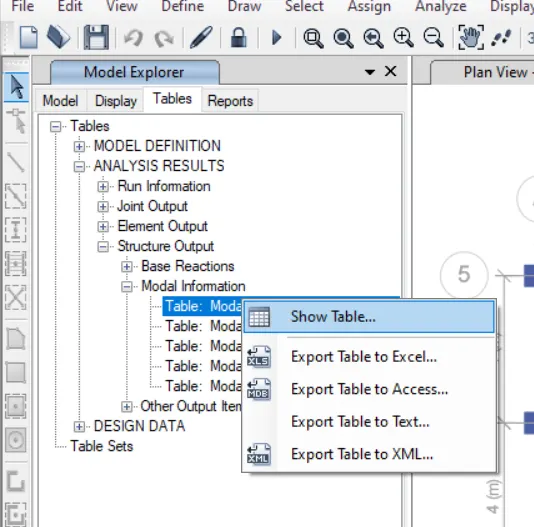
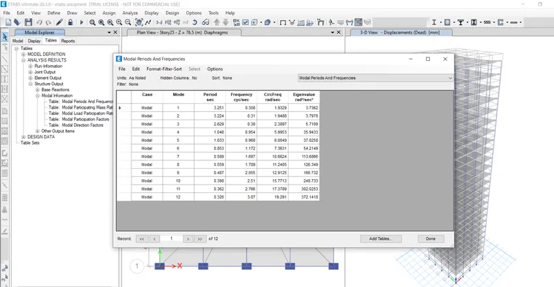
Check list
- Result of fundamental translationl natural period in x direction is 3.251
- Result of fundamental translationl natural period in y direction is 3.224
- Result of torsional mode time period should be lesser than x and y direction time period, the value obtained is 2.629
Vertical irregularities
- Select modal mass participating ratio table
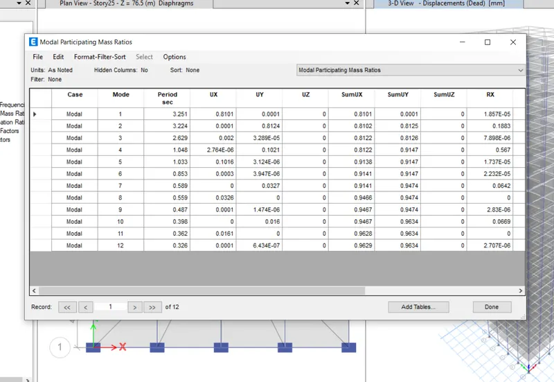
- First three modes together should contribute at least 65% in mass participation factor in each principle direction -yes it does satisfy
- Fundamental lateral natural periods in two principal plan directions are away from each other by at least 10%- no it no not away by 10%
Inert-storey drift
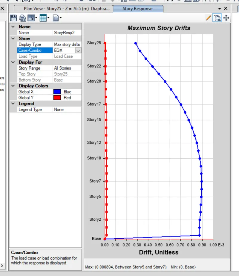
Storey drift shall not exceed 0.004 times the storey height for the base shear with no load factor
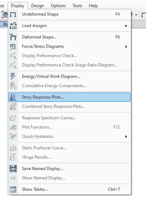
- To check the storey drift, do to display option and select story response plot and then enter the details
- Result of Maximum story drift in x
- Result of Maximum story drift in y
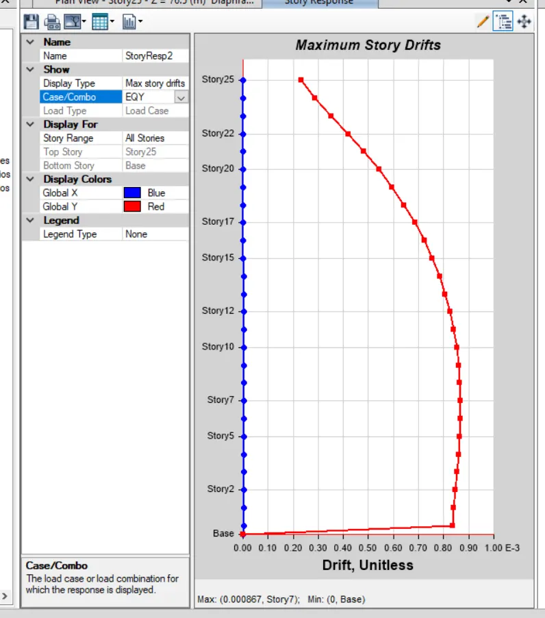
- So as per the clause 7.11.1.1, the maximum inter storey drift is milited to 0.004 for each storey height. But our value is within the code limits.
Result: The modeling and anlysis on 25 storey building is completed.