Modelling of 25 storey building with the specified properties using ETABS
Challenge 6 – ETABS modelling of a 25 storey building
Model a 25 storey building on ETABS with structural properties as specified below. Ground floor or plinth floor level can be taken at a height of 1.5 metres from the base. Each of the successive 25 storeys has a storey height of 3 metres.
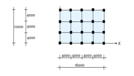
Structural Element Sizes
- Beams : 300 × 400 mm
- Columns : 800 × 800 mm
- Slab : 150 mm thick
Material Properties
- Grade of Concrete : M30
- Grade of Steel Reinforcement Bars : Fe 415
Loading
- Dead Load on beams from infill wall : 10 kN/m (Let us assume the same for roof floor in view of parapet)
- Live load on floor : 3 kN/m2 (Let us assume the same for roof floor)
a) Buildings are assumed to be pinned at the base
b) All columns in all storey are of the same size
c) All beams in all storeys are of the same size
d) Building is located on Soil type-II and in Zone-III. Assume other factors if required.
Aim: To model a 25 storey building on ETABS with structural properties as specified. Building is pinned at the base, all columns and beams in all storey of same given size 800x800 mm and 300x400 mm respectively. The slab is taken with thickness 150mm. M30 concrete grade is taken and steel bars of grade Fe415 is taken. Soil type is taken as II and as per building location seismic zone is taken as III.
Ground floor or plinth floor level is taken at a height of 1.5 metres from the base. Each of the successive 25 storeys is taken with storey height of 3 metres.
Procedure:
1. open Etabs software and choose new model
2. Choose use built-in settings and give the units, codes accordingly as shown
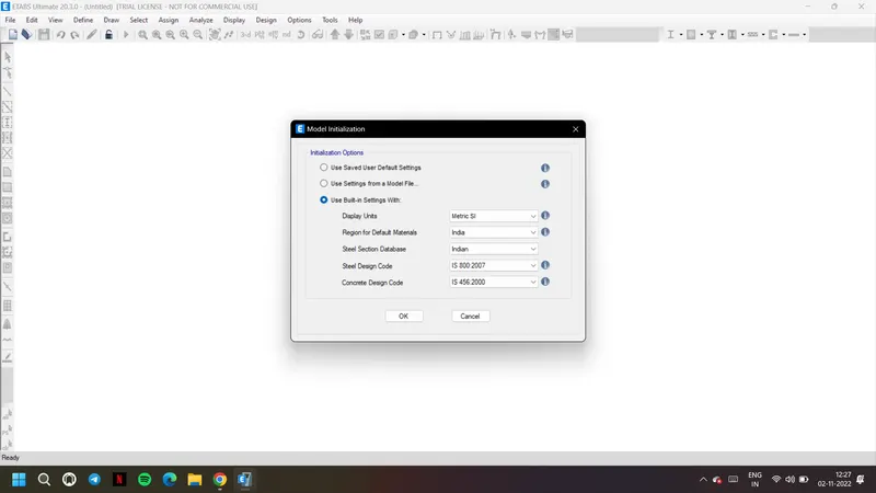
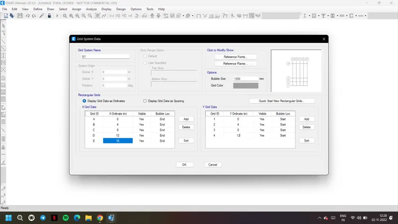
3. Now we get grid system tab, choose display grid data and as per the plam give 5 grids in x direction
4. And 4 grids in y-direction with 4m distance as shown
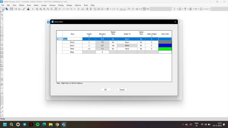
5. Now go to storey data and give plinth beam with 1.5m height and other storey with 3m

6. Keep the story 1as master story and keep it as similar story for all other stories as shown
7. Now add the remaining stories to form the 25 story building and let them also have similar to story 1
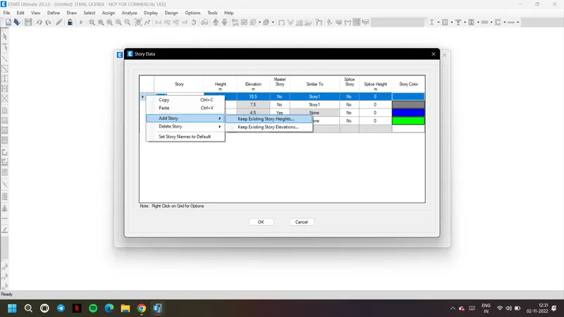
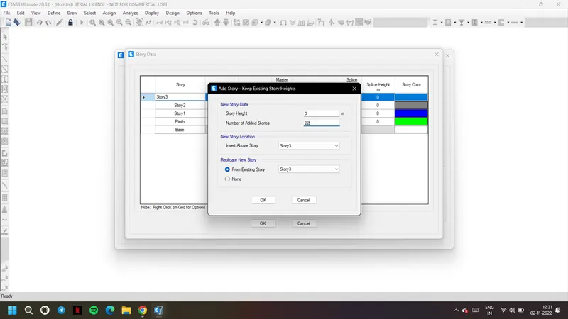
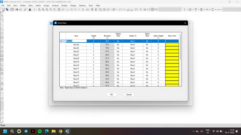
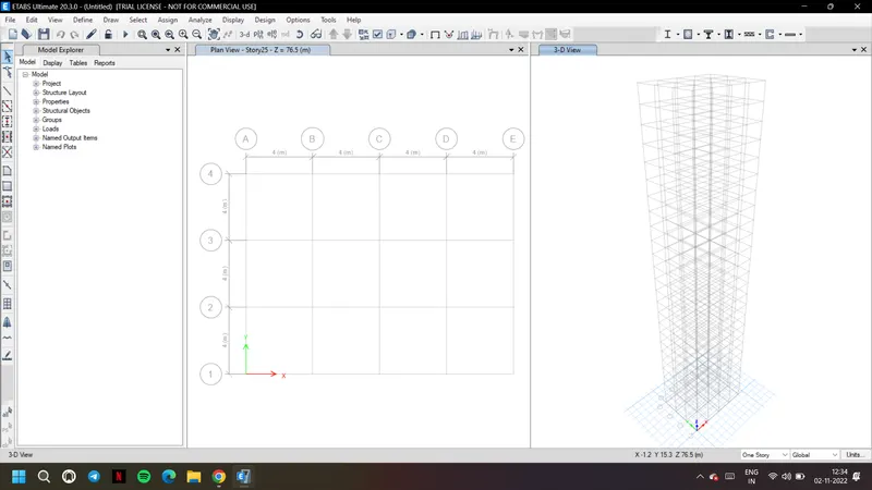
9. After closing the tab, the building is created in this way with given grids and story data
10. Now to assign material property, go to material properties from define tab
11. Choose concrete of grade 30 and rebar steel of Fe415 as mentioned
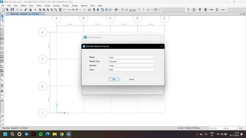
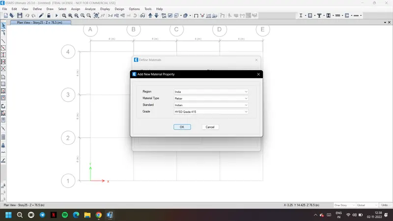
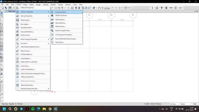
12. Now go to section properties and frame sections to define frames
13. Define the beam, B300x400 and modify to set rebar settings and save
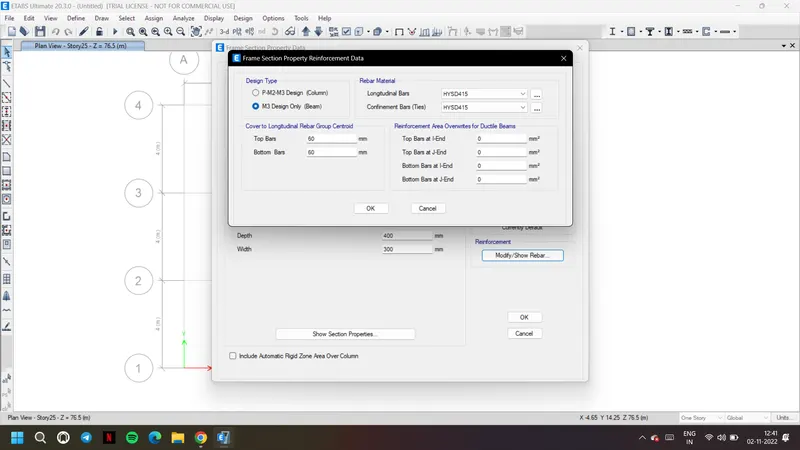
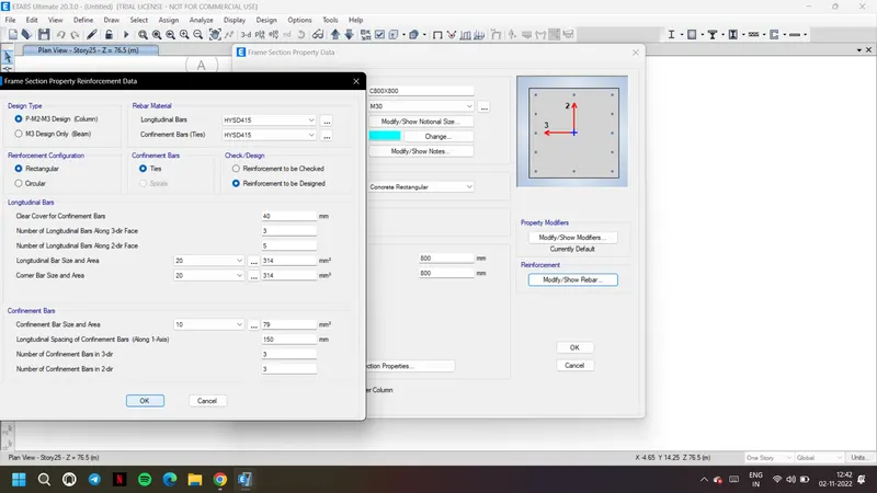
14. Similarly create frame column, C800x800 and give tis properties and rebar as Fe415
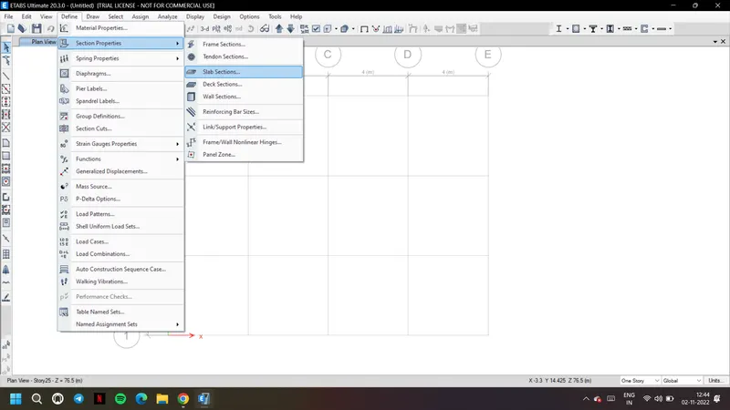
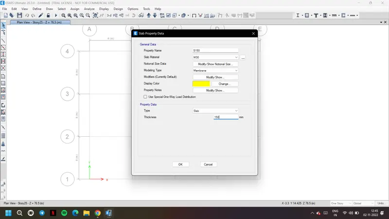
15. Now for slab go to slab sections and create a slab with 150mm thickness
16. Now go to load patterns from define tab and add the given loads accordingly
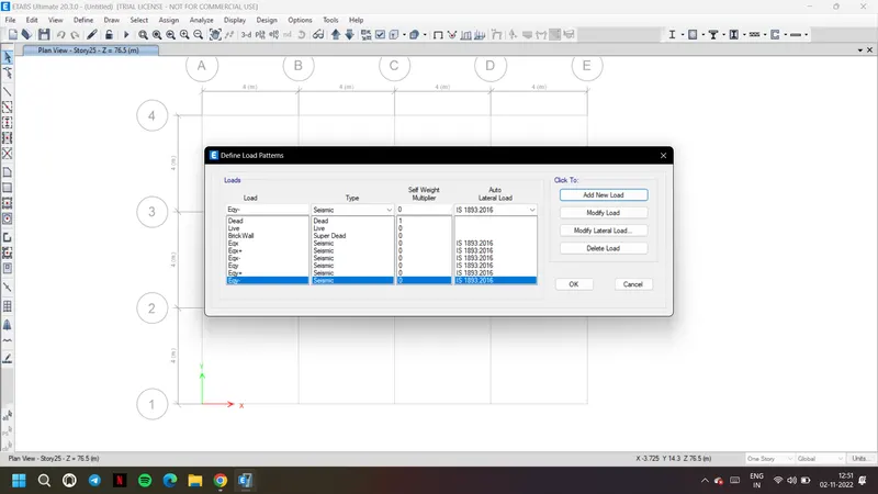
17. For lateral loads, go to modify lateral load and set them accordingly as shown
18. As given seismic zone is III and soil type is II
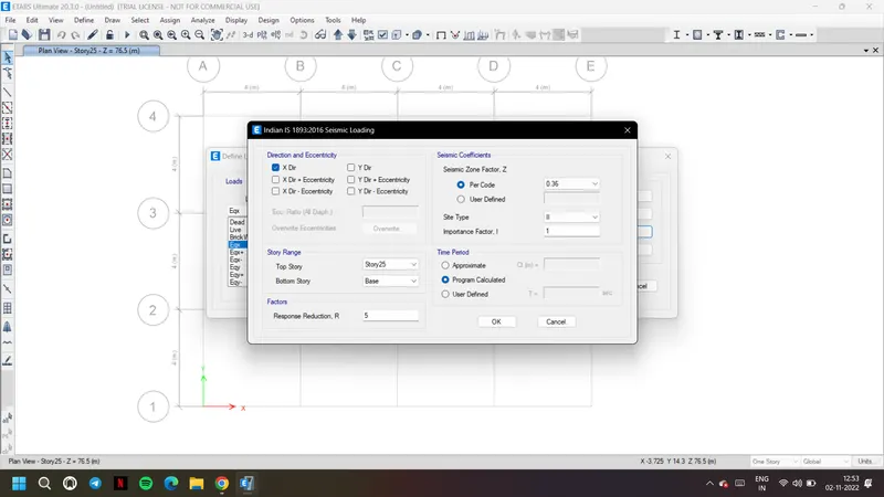
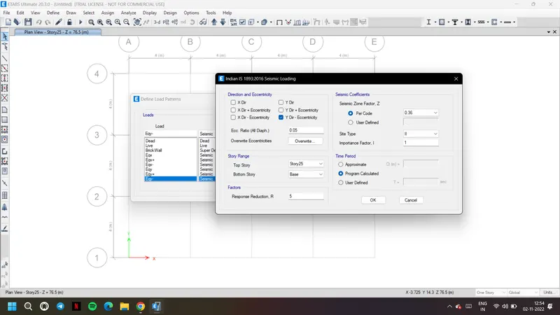
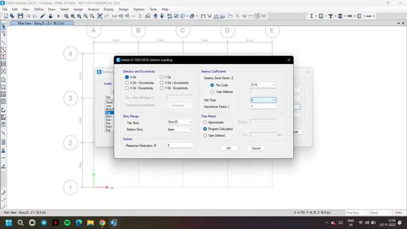
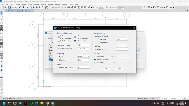
19. Now go to mass source and set teh load patterns accordingly as per code
20. Live load being 25 percent and dead, brick load with 100 percent mass

21. Go to load combinations from define tab and choose add default design combinations
22. As per the selected code and load patterns, we get the load combinations
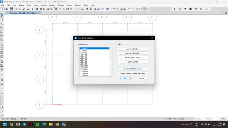
23. Now to draw columns, choose quick draw columns and choose property as column C800x800
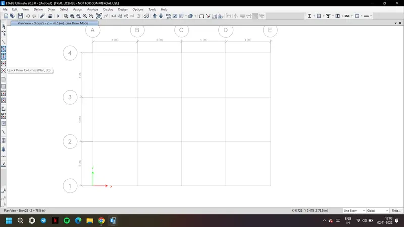
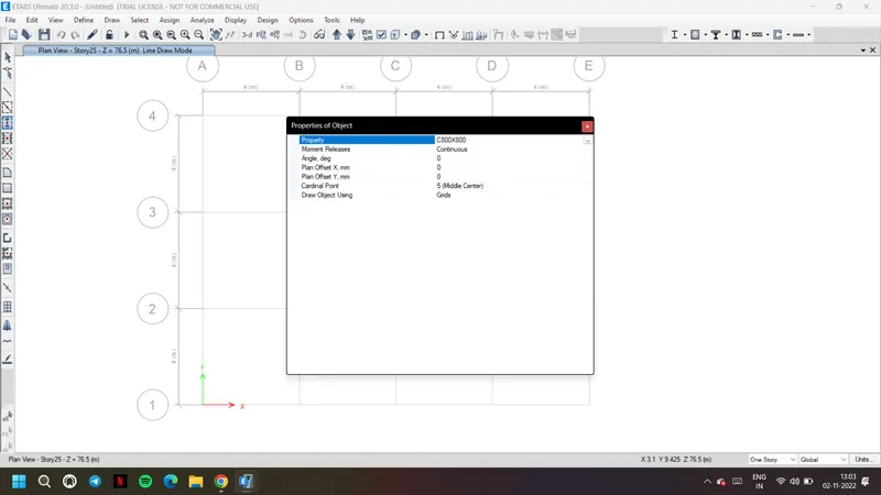
24. Choose option all stories as we need columns at each and every storey
25. Place the columns at each grid as shown as per the plan
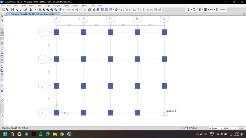
26. Similarly now choose beam and place them as shown connecting the columns
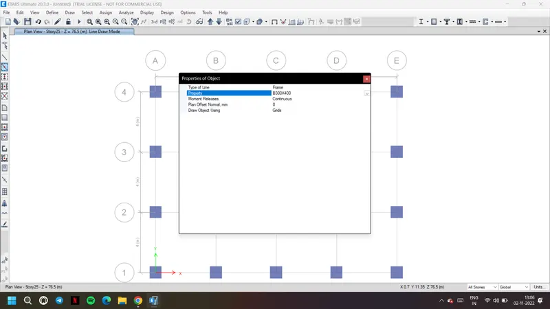
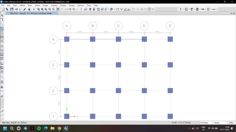
27. There is also an option to replicate the created frames using replicate from edit tab
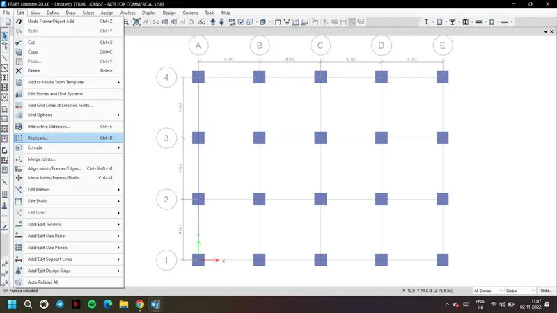
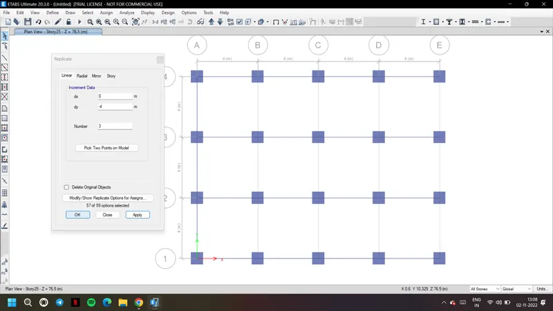
28. Replicate the beams to all other bays as shown using replicate option

29. Now open the plan view of story 1 and choose similar stories to create slab for all the stories
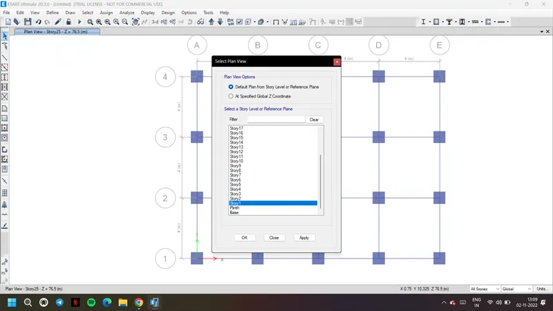
30. Choose quick draw slab and choose S150
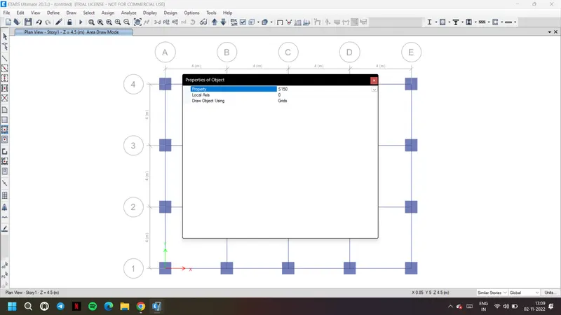
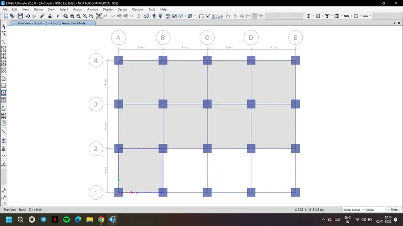
31. Place the slab in story 1 so that they will replicate in all other similar stories
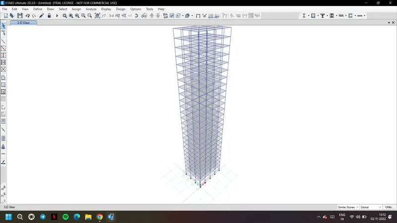
32. The 3D view after creating beams, columns and slabs
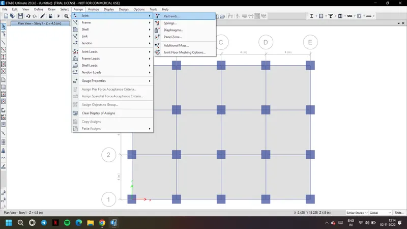
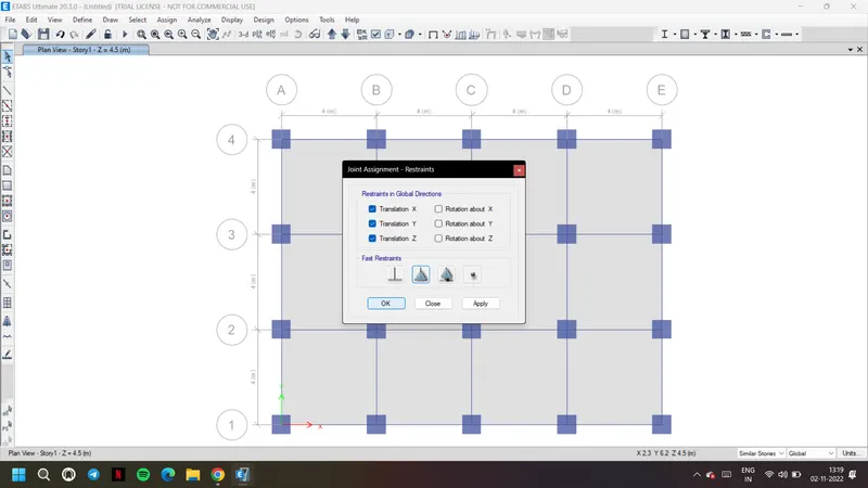
33. Now go to assign and restraints and choose pinned joints as mentioned
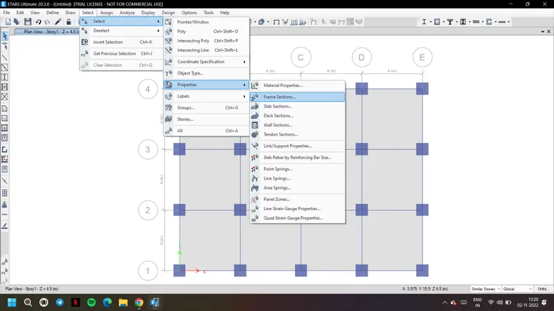
34. Now to apply loads, go to select and select frame sections to select only the beams
35. Select the beams, go to assign framed loads and distributed
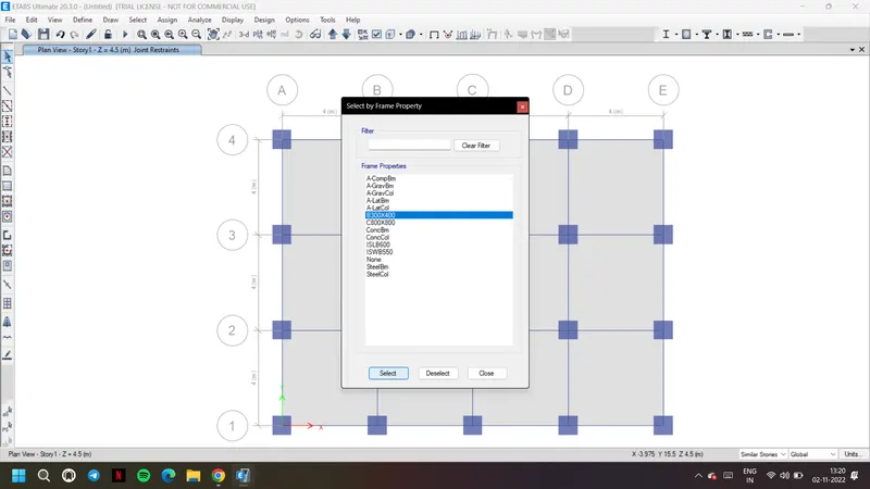
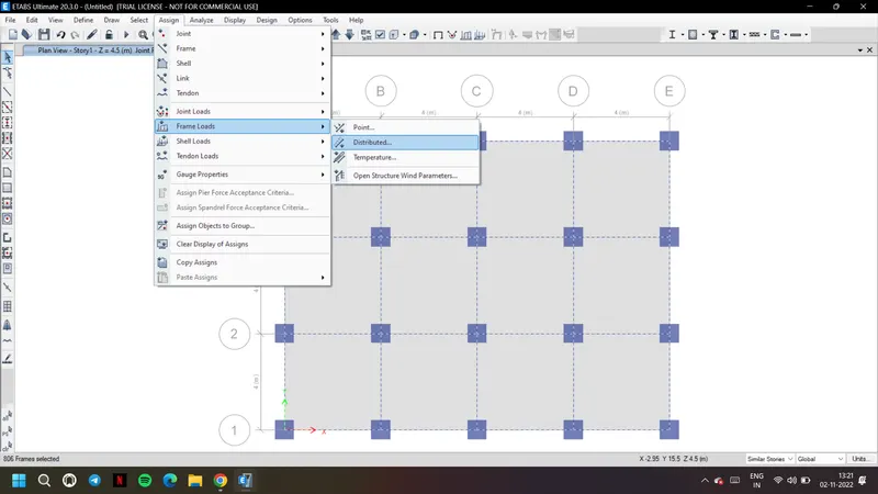
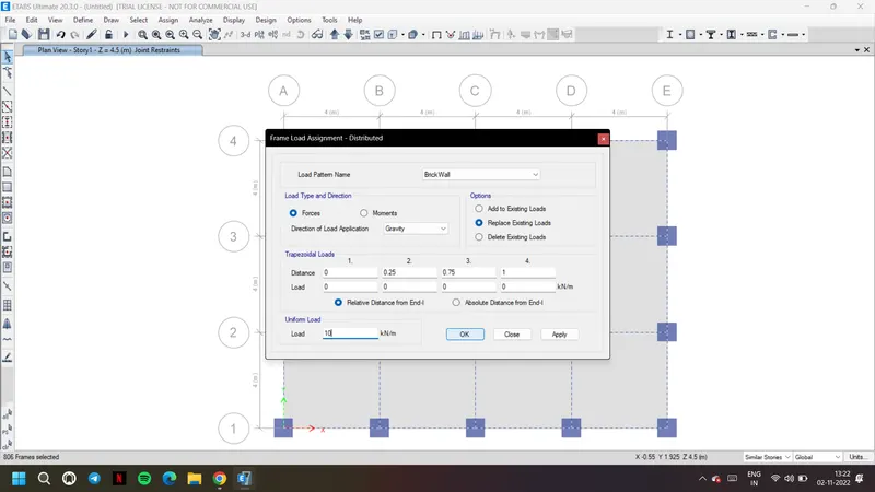
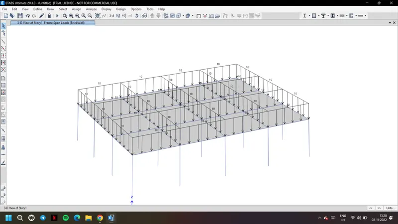
36. Choose brick wall and give it as 10kN/m as given
37. Now from slab selections select slab. Go to assign shell loads, uniform.
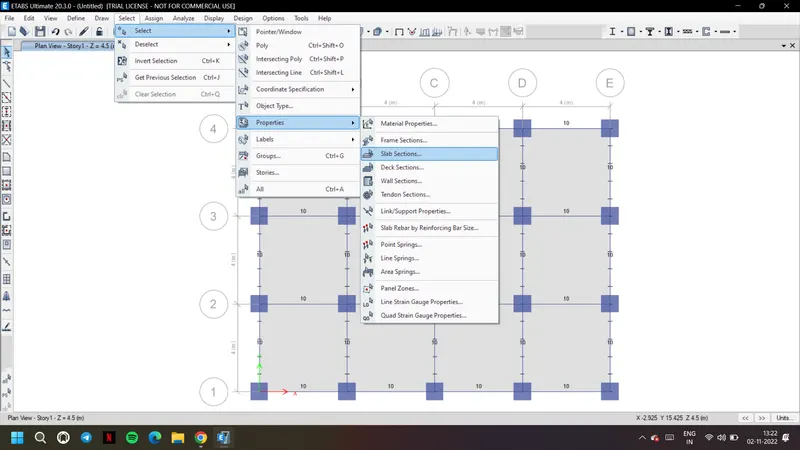
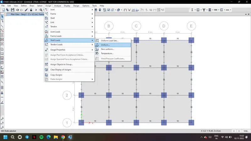
38. Apply load of 3 kn/m^2 live load on slab
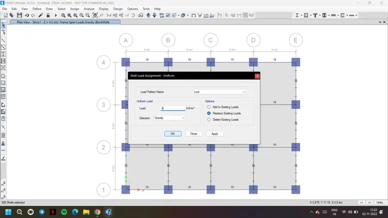
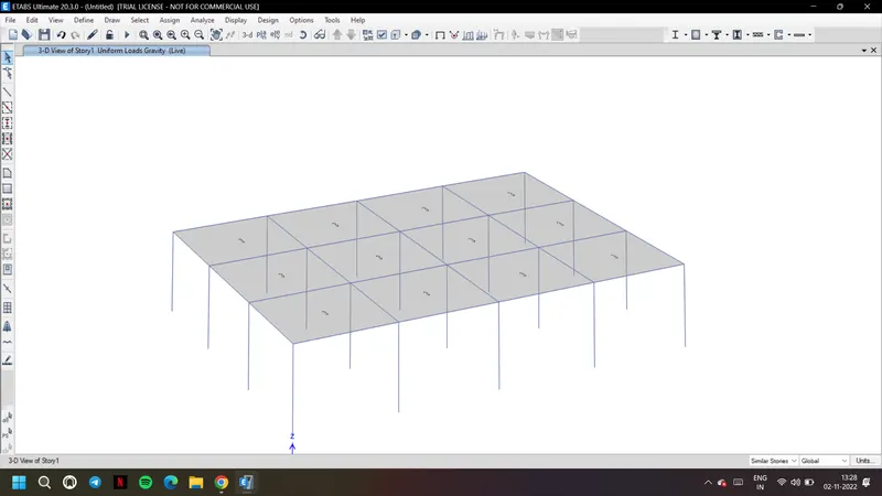
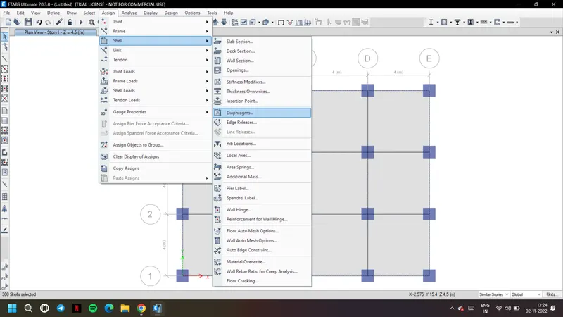
39. Now again select slab, go to assign tab shell and diaphragms
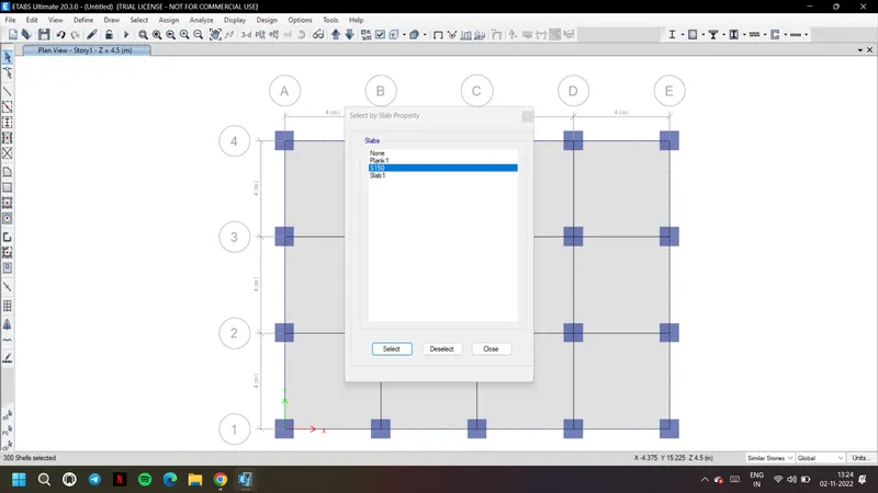
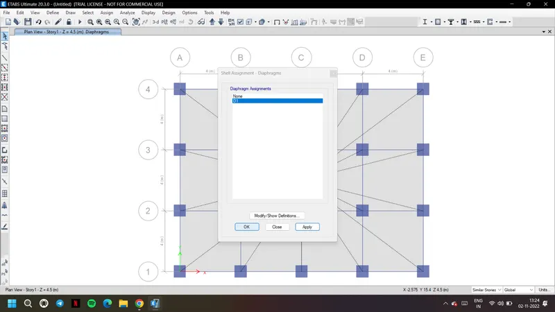
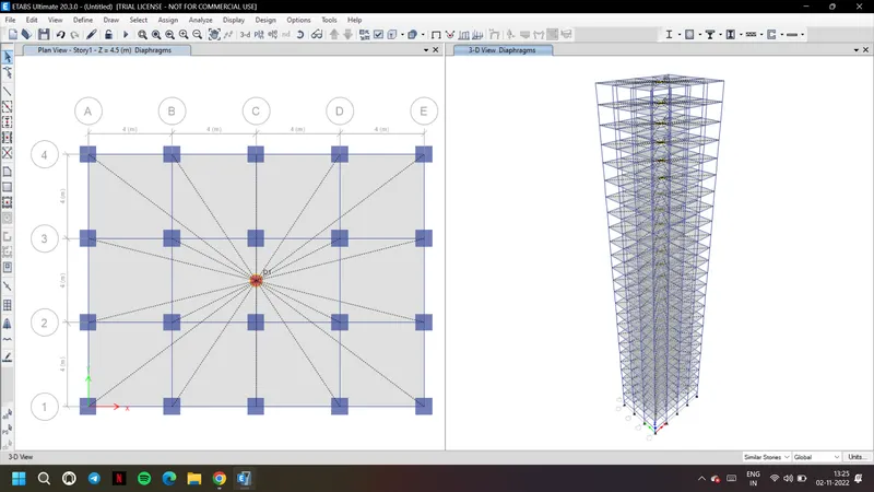
40. Choose D1 and apply to get the center of mass of the building as shown
41. Before analyzing the structure go to check model from analyze tab as shown
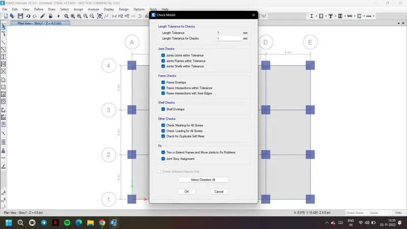
42. It is clear that no overlapping or missings frames in the designed structure
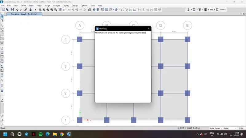
43. Now choose run analysis
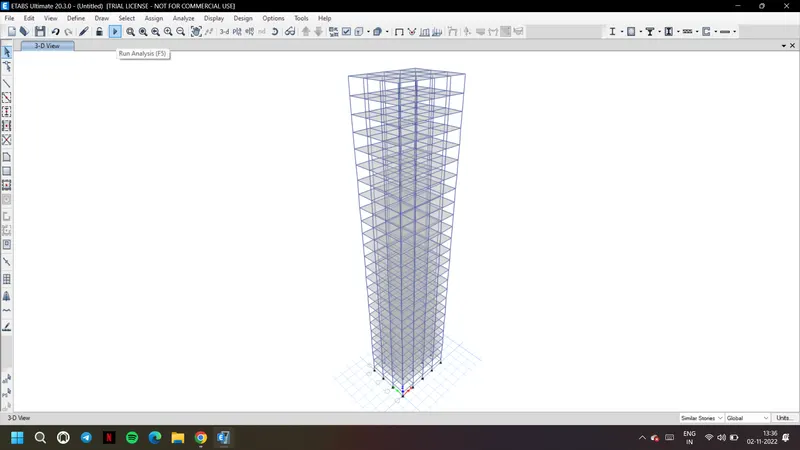
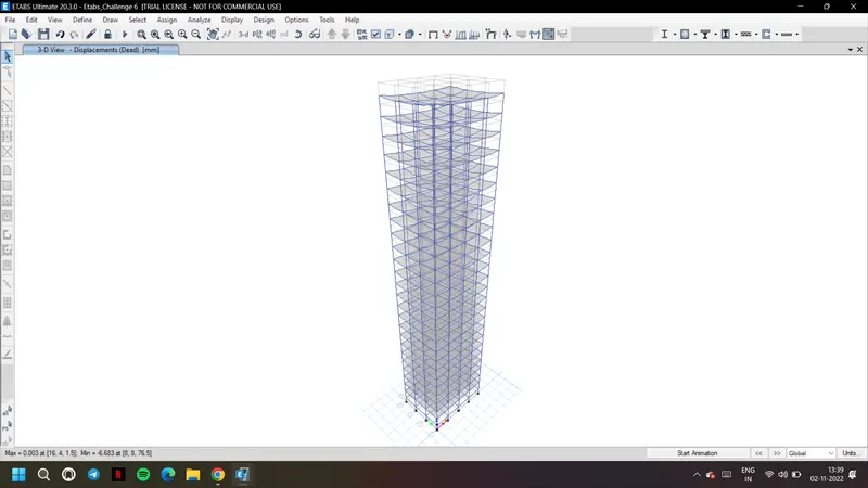
44. After completion of analysis we get the deflected shape of the building with given load combinations
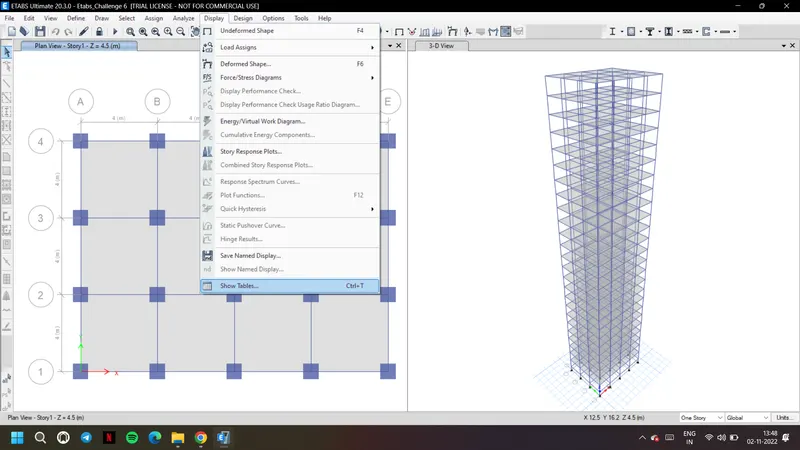
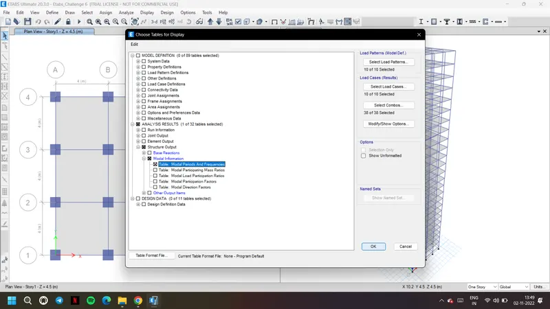
45. From display tab, show tables. We can see the deflection and diagrams, graphs based on each load
Result:
A 25 storey building with given structural properties is designed on ETABS following all the given material properties and loading behaviour.
OBSERVATIONS:
a) Carry out the following exercises:
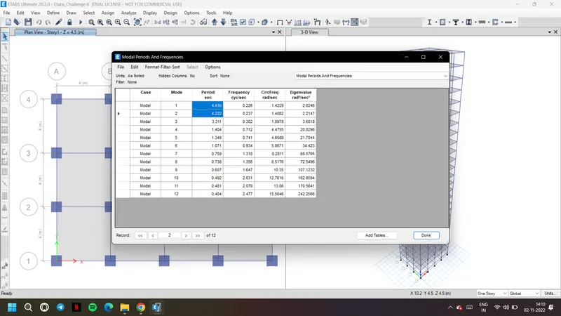
- Check if the translational fundamental natural period of vibration in both the x and y direction is approximately: Tx1= 4.4 second Ty1= 4.2 second
Ans: From the results, the translational fundamental natural period of vibration in both the x and y direction is
Tx1= 4.41 second Ty1= 4.22 second which is almost similar to given Tx1= 4.4 second Ty1= 4.2 second
b) Check if the following provision in Table 5 of IS 1893 (part 1) – 2016, on torsional irregularity satisfied:
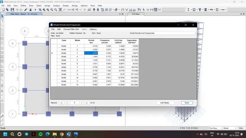
The natural period corresponding to the torsional mode of oscillation must be less than the two fundamental translational modes of oscillation along each principal plan directions.
Ans: Yes mode three translational natural period i.e., 3.31 is less than the fundamental modes one and two. Hence satisfied.
c) Check if the two provisions of clause 7 in Table 6 (shown below) of IS 1893 (part 1) – 2016, regarding vertical irregularity is satisfied
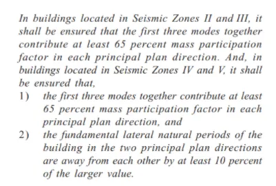
Ans: Yes, the modal satisfies the provisions of clause 7 in Table 6 of IS 1893 (part 1)-2016, the first mode itself is contributing 80 percent of mass participation factor in X and Y directions
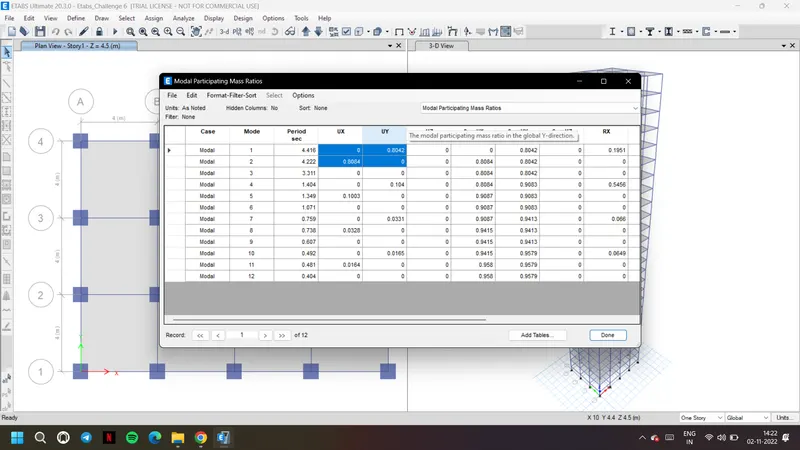
The translational fundamental natural period of vibration in both the x and y direction is Tx1= 4.41 second Ty1= 4.22 second, they are not away from each other by 10 percent as per the code. So the modal is not following the second point of clause 7 in Table 6 in code regarding vertical irregularity
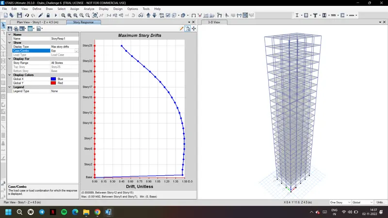
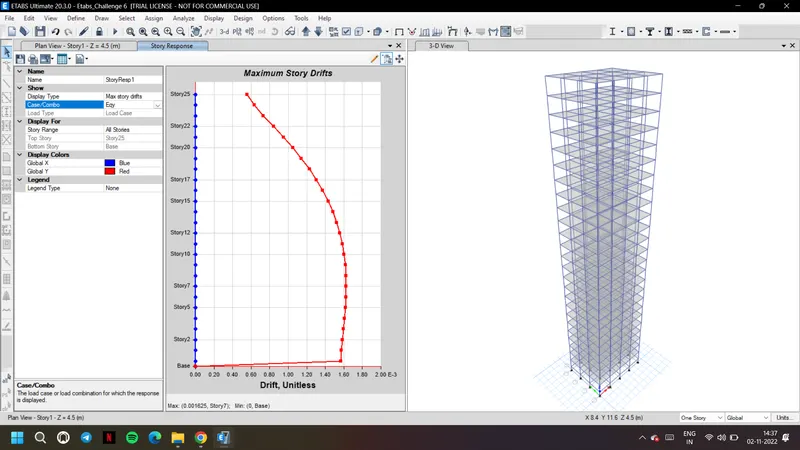
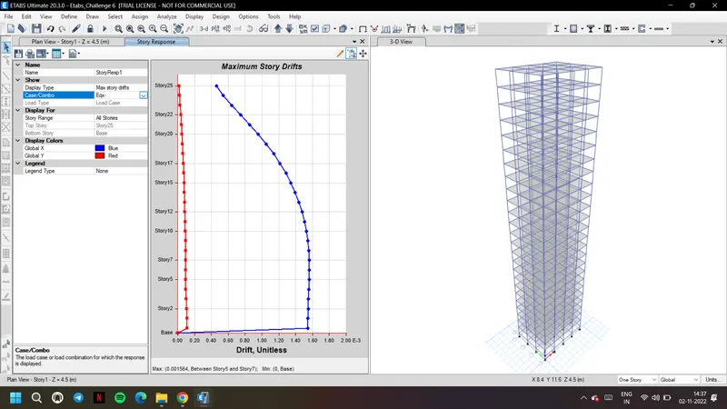
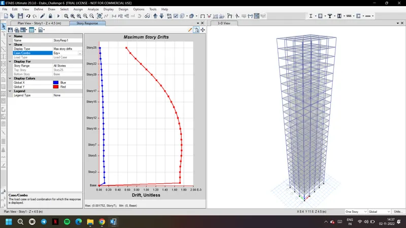
d) Check if provision on inter-storey drift limitations in clause 7.11.1.1 satisfied. Please note that this check is for Serviceability Limit State and hence is for situation when stucture is subjected to unfactored seismic base shear
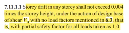
Ans: Under the base shear, in each storey the storey drift is not exceeding 0.004 times the storey height in this case 0.004x76.5 = 0.306. As shown below every storey max drift is around 1 and 2 it is not reaching 3 or 4 as mentioned. So the modal has satisfied provision on inter-storey drift limitations in clause 7.11.1.1 as per the code.