Modelling of 25 storey building with the specified properties using ETABS
AIM:
To Model a 25 storey building on ETABS with structural properties as specified below. Ground floor or plinth floor level can be taken at a height of 1.5 metres from the base. Each of the successive 25 storeys has a storey height of 3 metres.
INTRODUCTION:
ETABS is an engineering software product that caters to multi-story building analysis and design. Modeling tools and templates, code-based load prescriptions, analysis methods and solution techniques, all coordinate with the grid-like geometry unique to this class of structure. Basic or advanced systems under static or dynamic conditions may be evaluated using ETABS. For a sophisticated assessment of seismic performance, modal and direct-integration time-history analyses may couple with P-Delta and Large Displacement effects. Nonlinear links and concentrated PMM or fiber hinges may capture material nonlinearity under monotonic or hysteretic behavior. Intuitive and integrated features make applications of any complexity practical to implement. Interoperability with a series of design and documentation platforms makes ETABS a coordinated and productive tool for designs which range from simple 2D frames to elaborate modern high-rises.
- Modeling of Structural Systems
- Loading. Analysis, and Design
- Output, Interoperability, and Versatility.
Modeling of Structural Systems:
Fundamental to ETABS modeling is the generalization that multi-story buildings typically consist of identical or similar floor plans that repeat in the vertical direction. Modeling features that streamline analytical-model generation, and simulate advanced seismic systems, are listed as follows:
- Templates for global-system and local-element modeling
- Customized section geometry and constitutive behavior
- Grouping of frame and shell objects
- Link assignment for modeling isolators, dampers, and other advanced seismic systems
- Nonlinear hinge specification
- Automatic meshing with manual options
- Editing and assignment features for plan, elevation, and 3D views
Loading, Analysis, and Design:
Once modeling is complete, ETABS automatically generates and assigns code-based loading conditions for gravity, seismic, wind, and thermal forces. Users may specify an unlimited number of load cases and combinations.
Analysis capabilities then offer advanced nonlinear methods for characterization of static-pushover and dynamic response. Dynamic considerations may include modal, response-spectrum, or time history analysis. P-delta effect account for geometric nonlinearity.
Output, Interoperability, and Versatility:
Output and display formats are also practical and intuitive. Moment, shear, and axial force diagrams, presented in 2D and 3D views with corresponding data sets, may be organized into customizable reports. Also available are detailed section cuts depicting various local response measures. Global perspectives depicting static displaced configurations or video animations of time-history response are available as well.
ETABS also features interoperability with related software products, providing for the import of architectural models from various technical drawing software, or export to various platforms and file formats. SAFE, the floor and foundation slab design software with post tensioning (PT) capability, is one such option for
export. CSI coordinated SAFE to be used in conjunction with ETABS such that engineers could more thoroughly detail, analyze, and design the individual levels of an ETABS model.
While ETABS features a variety of sophisticated capabilities, the software is equally useful for designing basic systems. ETABS is the practical choice for all grid like applications ranging from simple 2D frames to the most complex high rises.
PROCEDURE:
step:1
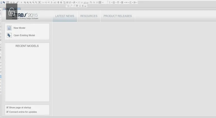
• Open the Etab software
• On the left side top corner select the new model as shown below
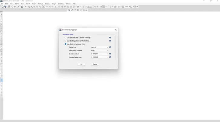
- After click the new model there open the model initialization dialouge box
- In the box we can see a 3 option and then select the last option
- Set the unit as " METRIC SI" and set the steel section data base as "indian" and set the code as 800:2007 for 3rd option. finally set the code 456:2000 for last option
STEP: 2
- After finishing the previous process then open new model quick template opened automatically
- we can set the grid dimension as custom and also the story dimension
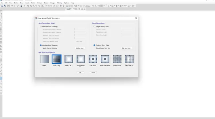
- Next we can set the number of storys and height of thestory in x grid data
- And also same the process in y grid data and then ok
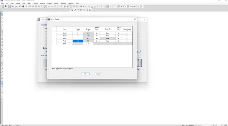
- Next we open the story data and we need to add the story data upto 25 story and then
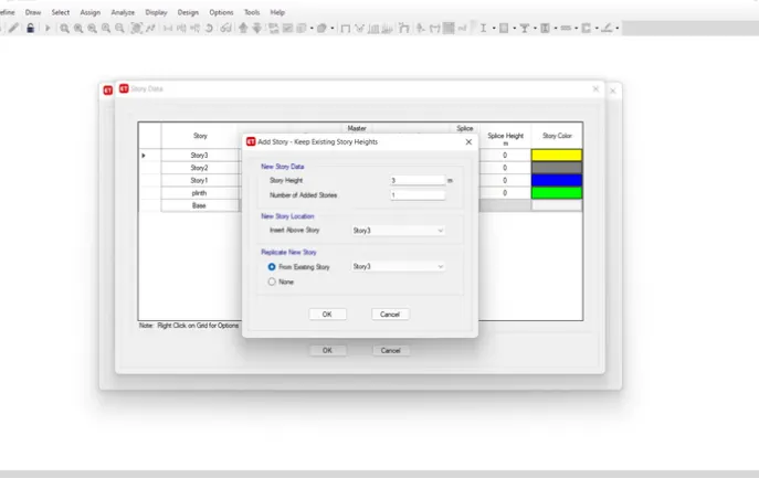
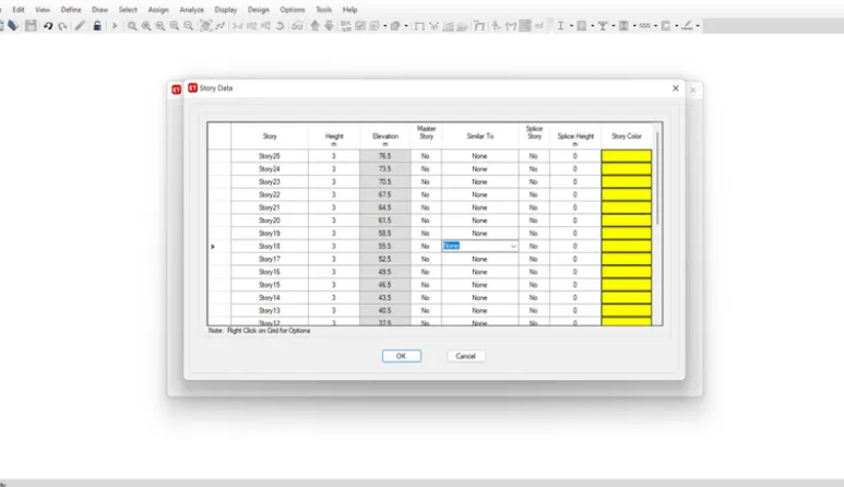
- added story data as shown below in picture
- And we give the name for the story as base, plint, storyl, story................25.
- And set the height of the plinth as 1.5m and other all as 3m
- Then set the all story similar to story 1 except plinth
- Finally click ok
STEP: 3
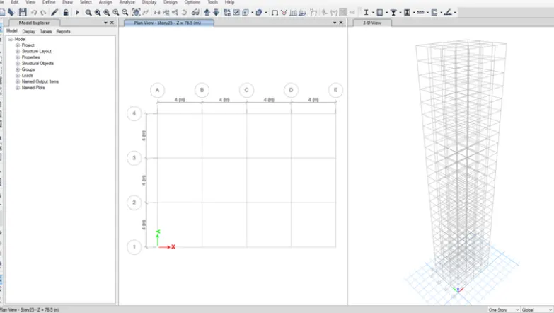
• In there we can saw the grids and story are created below in the picture
• Next we go to the define option and select the material properties
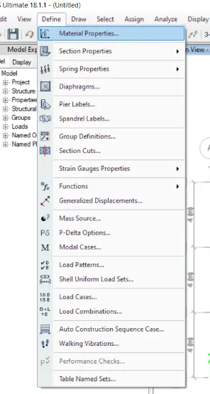
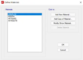
- Then there open a define material box and select the add new material option
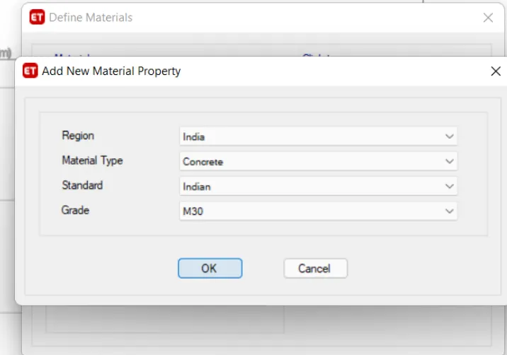
- And select the region "INDIAN", material type "concrete",standard "INDIAN", grade "M30"
- then click ok
STEP: 4
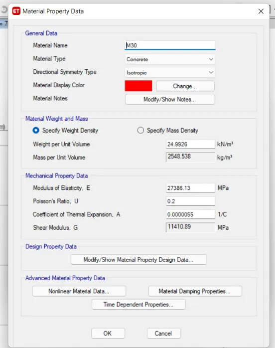
• After here opening the material property data box
• Set the material name like M30
• Then material type "Concrete"
• Others are automatically update with use code given
finally click ok
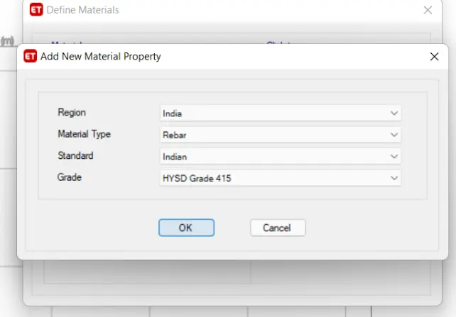
- Again click the add new material
- again set add new material properties
- Here we can set the matrial properties as "rebar
- and then click ok
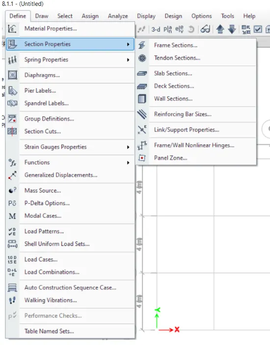
- Next go the define option and select the section
- Load Combinations...
- Auto Construction Sequence Case....
- !! Walking Vibrations...
- p Performance Checks.
- Table Named Sets...
- properties and go to the frame section.
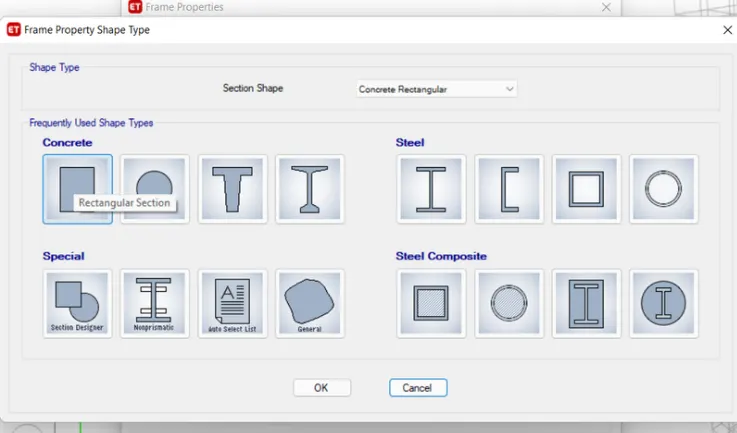
- Select the concrete rectangle and click ok
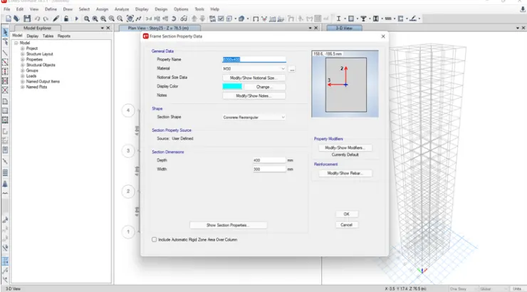
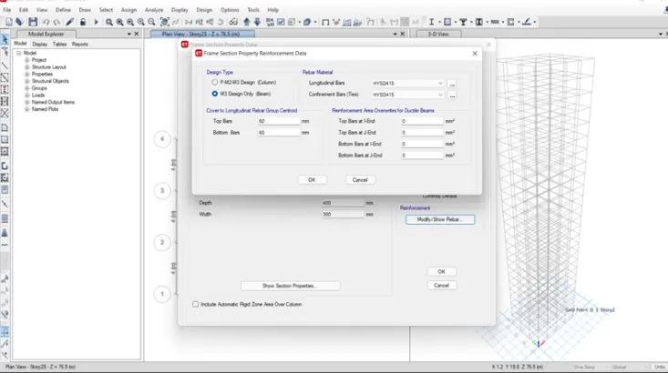
- And set the material name as (B300 X 400) and material "M30" • Go to the modify show rebar
- And set the design type M3 beam and give the rebar material as HYSD 415 for both
- And then click ok
STEP: 5
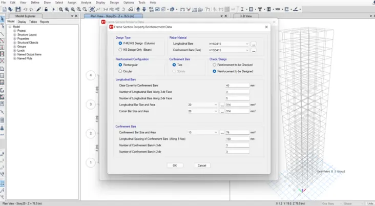
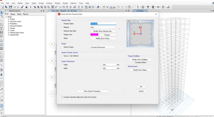
- Next we can open the same concrete rectangle and select the column in here And set the material name as (C800 x 800) and material "M30"
- Go to the modify show rebar
- And set the rebar as HYSD415 for both
- Finally click ok
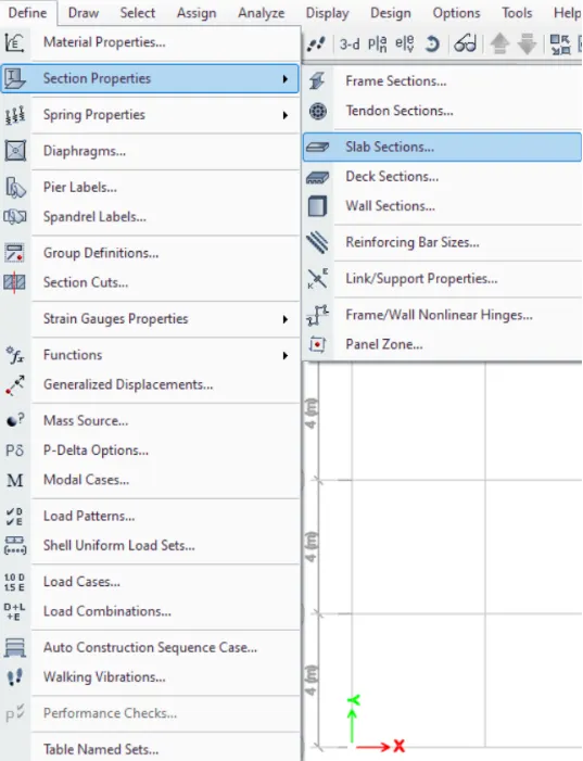
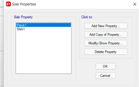
- Go to the define tab and select the section properties and then select the slab section
- After there open a slab properties box
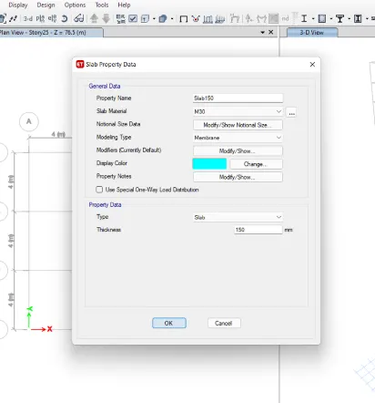
- and click modify option and then set properties name "slab 150"
- Give the slab material " M30"
- And modeling type " membrane"
- Give the thickness of slab as 150m
- Finally click ok
STEP: 6
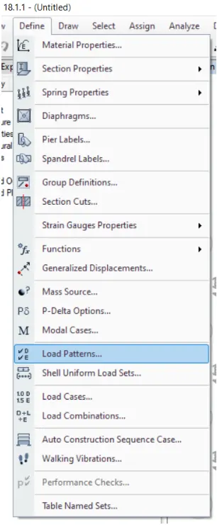
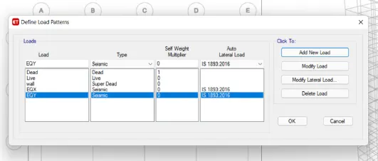
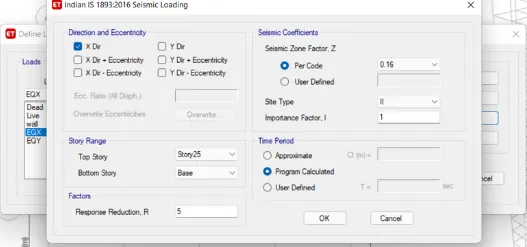
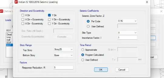
• Go to the define and select the load patterns set or make the loads like dead, live, wall, EQX, EQY
• Give the IS code value for EXQ, EXY
• Taken the both load and set the (DIRECTION AND ECCENTRICITY)
• EXQ- only select the x-dirction
•EXY - only select the y-dirction And set the seismic zone factor for per code as per the rule of code book (0.16) And set the site type as (1)
• This process is same for both the EQX, EQY
• Here wall load is super dead load
STEP: 7
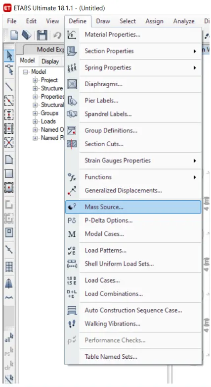
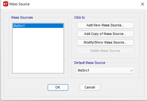
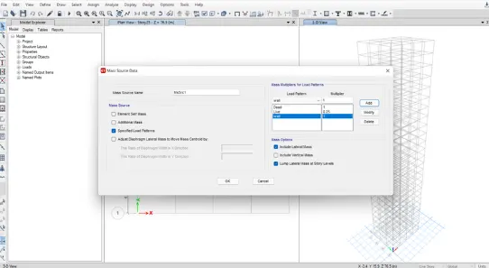
• Taken the define option and select the mass source • After opening the mass source dialouge box
• Just give a modify option to modify it Just select only the specify load pattern and other then unselect it
•And give the load patterns as dead load, live load, wall load
• Give the value of the dead load and wall load as (1) give the value of live load as (0.25)
• Then click ok
- Again go to the define option
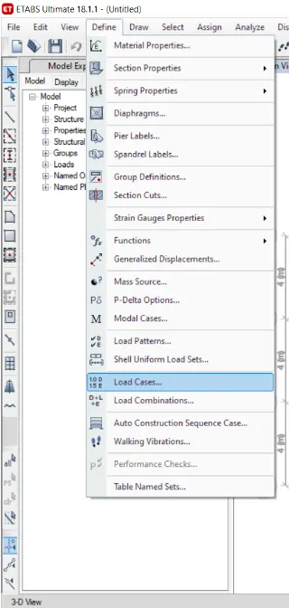
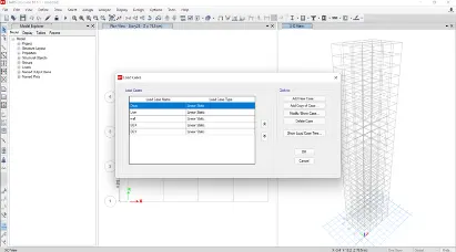
- And select the load cases
- After opening the load cases dialouge box check once
- And then click ok
STEP: 8
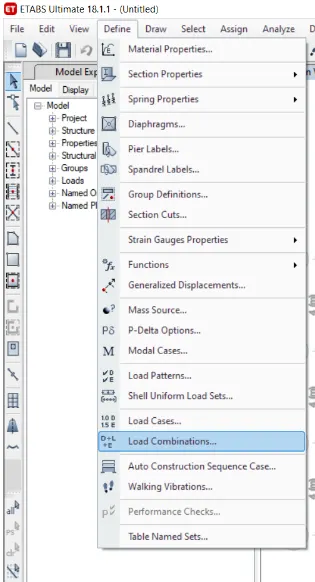
• Again go to the define option and select the load
combination
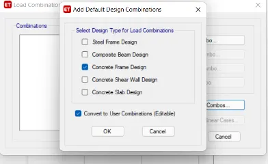
After opening the load combination dialouge box Just select the concrete frame design
• And select "converet to user combination" option
• Then click ok
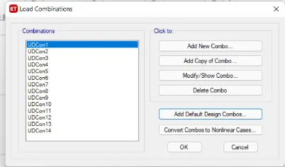
• After that we can see the combination of load are automatically placed with help of code designs
Let now we can arrage the materials and loads on the design
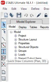
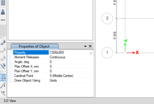
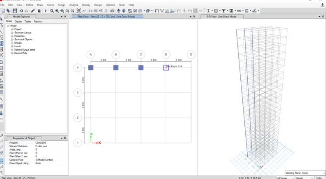
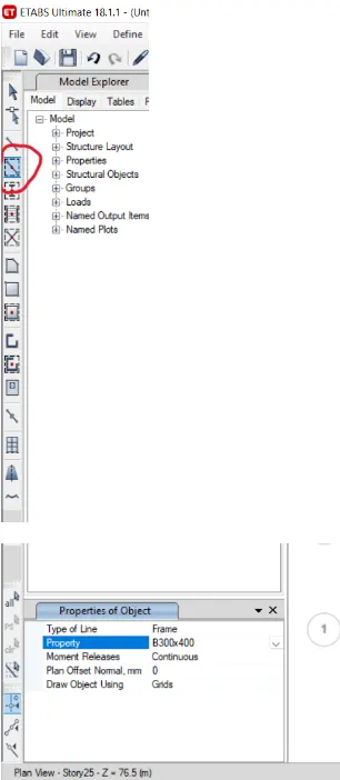
- go to the quick draw column option in the left to corner After clicking the box will appear in left bottom corner
there we want to set the properties as we alredy maked column
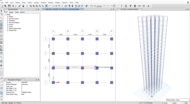
- And go the plan view and and placed the coloumn on
- the grid. Is shown in the below image
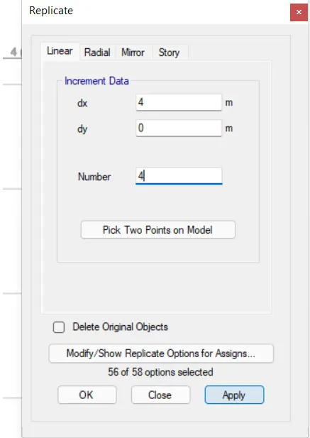
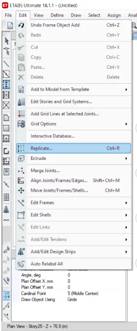
- Just use the replicate option to make the multiple or copy paste the column to all the grid
- Use the quick draw beam option in the left corner
- After clicking the box will appear in left bottom corner there we want to set the properties as we alredy maked beam (B300 x 400)
- And go the plan view and and placed the coloumn on
- the grid. Is shown in the below image
- Just use the replicate option to make the multiple or
- copy paste the beam to all the grid
STEP: 9
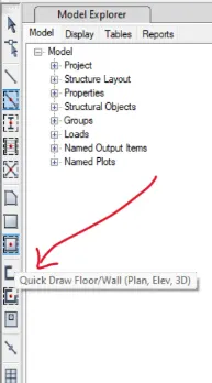
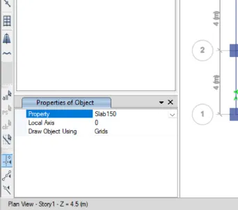
- Select the quick draw floor option to draw the slab select all stories and select the alredy create slab150 in the properties
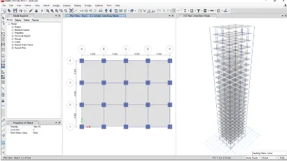
- And just pick in the story the all slab are create image as given below
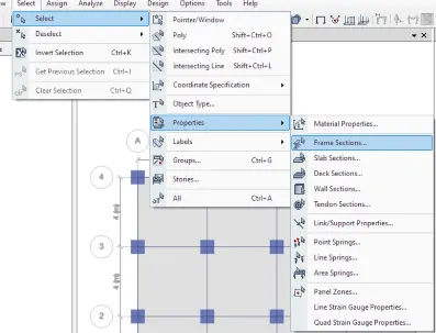
- Go to the select tab
- then pick the properties and select the freame sections
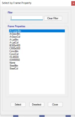
- go to the select by frame property dialouge box • Select the beams and click ok
- the selected beams are shown there in below image
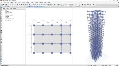
STEP:10
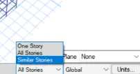
- open the selected plan views select the story 1 option And then select the similar story option
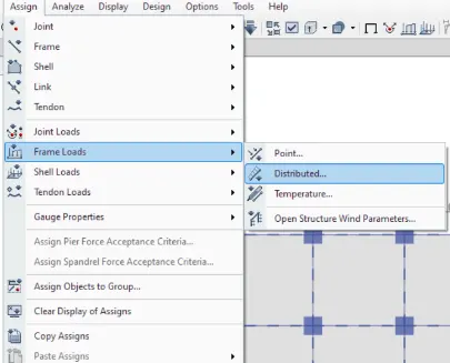
Go to the assign tab select the frame load
- And assign the distributed load
- • Select the load pattern name as "wall" (sdl) give the load value of 10 KN/m
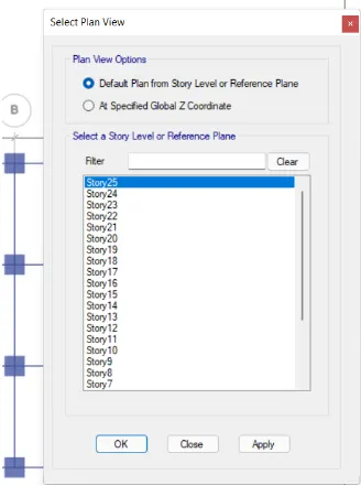
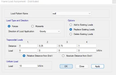
- Here loads are assigned image as given below loads are assigned for all the floors 9
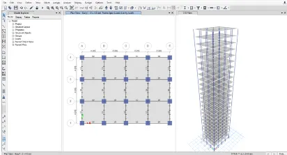
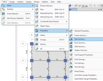
- Go to the select tab and pick the select option click the properties option and pick the slab section
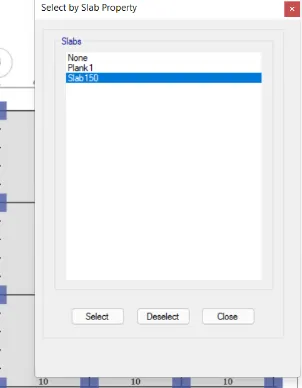
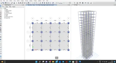
- In there open a dialouge box for select by slab property select the slab 150 the slab selected image as given below
STEP: 11
• Go to the assign tab and select the shell load And select the uniform
• Then there will open the (shell load assignment) dialouge box
• give the load pattern name as (live load) And give the load value as 3 kn/m2
• Finally then click ok
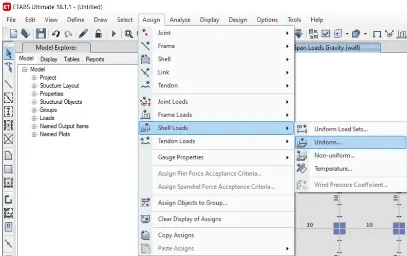
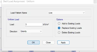
- The load as been assigned in the shell as been showed below the image
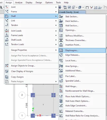
- Go to the assign tab
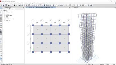
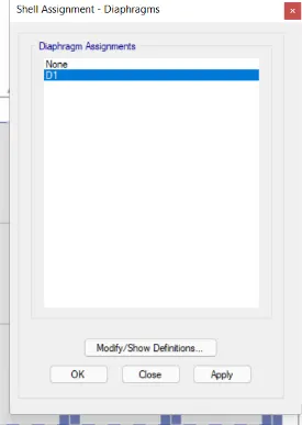
• Then select the shell and pick the diaphragms tHere automatically open the shell assignment dialouge box
• In the dialouge box select the (dl) option the diaphragms as placed at the center of the building
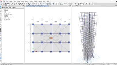
STEP: 12
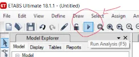
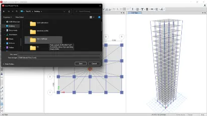
- After finishing the all loads aasignment just go to the run analysis option as shown below After click the run analysis option they asked a save file
- option just save the file and run the analysis
STEP: 13
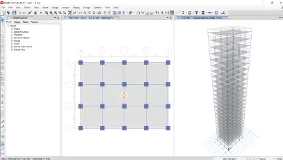
- After finishing the analysis
- the deformation of building as been showned in the screen and its shown in below the image
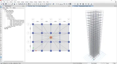
- Go to the model exploser tab
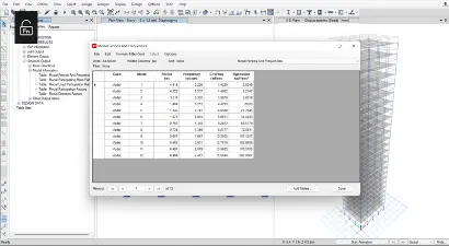
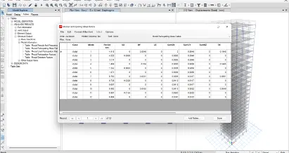
- pick the tabel option and pick the analysis results click the structural outputs
- and then click the model information
- finally we saw the tabels from the model information
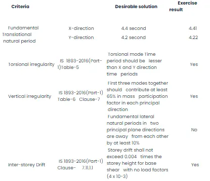
- pick the tables, they shown the model periods
STEP:14
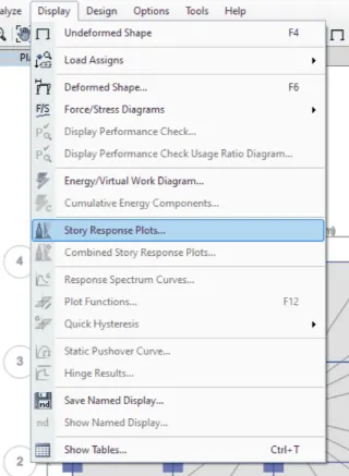
go to the display tab
then select the story response plots
after selection of story response plots they will open the
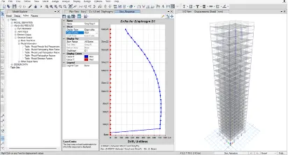
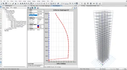
(drift for diaphragms DI) dialouge box set the diaph drift option and EQX,EQY. they will show the frequence diagram on the screen with values. then the image as been given below
RESULT: