Creating a Floor plan, Footing detail and Isometric view using AutoCad
AIM:
To create a Floor Plan, Footing Detail, and Isometric view of Steps and Gable Wall in Autocad.
INTRODUCTION:
The main objective of this assignment is to get in touch with various tools in AutoCAD like the rectangle, polylines, modifications tools like copy, move, offset and modes like snap mode and ortho mode. These tools will be understood by creating a footing detail, two bedroom building, cross section of a 2 bedroom building showing foundation details and isometric view of steps and gable wall.
Autocad is a drafting software that is used to draft drawings in the present case we are using AutoCAD to create various drawings using different tools in AutoCAD like Line, polyline, rectangle, fillet, chamfer, etc and along with that isometric drawing using specific commands and tools.
Note: Referencing alphabets are provided only when required.
PROCEDURE:
Setting The Drawing Sheet:
• Go to Application Menu and select New • In the 'Create New Drawing' dialog box, select the
'Imperial system in the 'Start from Scratch' option. • Next select the 'Decimal unit system from the 'Advanced Setup' option.
• Set the limits by entering LIMITS in the Command tab. The lower-left corner is specified as 0,0, and the upper right corner is specified as 100,100.
[Note: The above procedure is followed each time a new
drawing is to be created.]
1.LINE:
We can invoke the Line tool by pressing "L" in the command box and will have to specify starting point of the object we are used to draw. And mention the next remaining points to draw the diagram. Finally, closing the tool by pressing enter. This tool used enormous way in plotting structural drawing.
2.POLYLINE:
It means a many line in single entity. To draw a polyline we just invoke the "PL" command in the command box and used to draw the objects. By pressing enter to close the tool. In this way we has single element with multiple lines.
3.RECTANGLE:
We can draw rectangles by using Rectangle command in the command box and we give corners of the objectsto plot rectangle in drawing sheet. AutoCAD has modification tools alos. It used to modify,
move, copy, trim, extend, stretch the existing objects and
make things easily.
- MOVE:
Type "MOVE" in command box to invoke the tool and it used to move existing sketched objects wherever we want to shift and by pressing enter to close the invoking tool.
- COPY:
Type "COPY" in command box to wake this tool and it is used to copy the sketched objects where we need to draw and it is very helpful when we had to draw same element in different area's. So that we just draw one time and copied that to paste where we need to put.
- TRIM:
Type "TRIM to waking up this tool and it is used to cut the extended portion of drawing which sketche beyond the limit of actual dimensions.
- EXTEND:
It is exactly opposite to Trim tool. We can use this to extend the drawings and some places we need to complete unfinished edges.
- OFFSET:
This tool is helps to draw parallel lines, polylines, circle, etc., while we use this tool we enter the specific distance to offset the objects.
- ARRAY:
In some cases, we need to draw same objects in multiples times and specific distance. So that, we use this tool to draw by mention the required distance and number of rows and columns we need.
- FILLET:
The edges in a model are generally filleted to reduce the area of stress concentration. The fillet tool helps form round corners between any two entities that form a sharp vertex.
PART 1. CROSS-SECTION OF LOAD-BEARING WALL OVER SPREAD FOOTING:
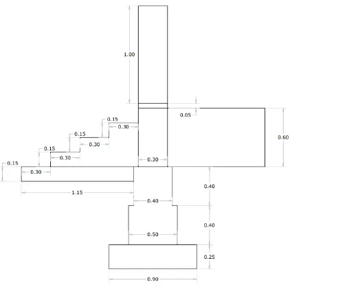
Commands Used:
1. Rectangle
2. Line
3. Offset
4. Trim
5. Dimension
Step by Step Procedure:
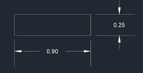
Step 1:
1. Type 'Rectangle' or 'REC' In the command box and
press Enter
2. Specify first corner point as 1,1
3. Specify the length of the rectangle as 0.9
4. Specify the width of the rectangle as 0.25
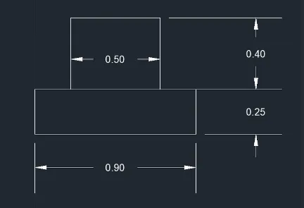
Step 2:
1. Type 'Line' or 'L' command in the command box and
press Enter
2. Specify the midpoint of the rectangle and draw a line
horizontally with 0.40
3. Select the Offset command and give offset distance
as 0.25
4. Select the previous line (ie., 0.40 line) and offset both
sides of that line.
5. Select the offset command again and give the offset
distance as 0.40
6. Select the below line and offset to the +y direction
7. Now select the Trim command and trim the unnecessary lines and edges
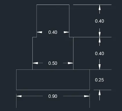
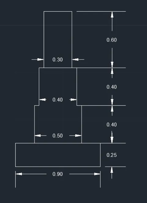
Step 3:
1. Type 'Line' or 'L' command in the command box and
press Enter
2. Specify the midpoint of the previous line (i.e., 0.50 line) and draw a line horizontally with 0.40 distance
3. Select the Offset command and give offset distance
As 0.20
4. Select the previous line (i.e., 0.40 line) and offset both
sides of that line.
5. Select the offset command again and give the offset
distance as 0.40
6. Select the below line and offset to the +y direction
7. Now select the Trim command and trim the
unnecessary lines and edges
Step 4:
1. Type 'Line' or 'L' command in the command box and press Enter
2. Specify the midpoint of the previous line (1.e, 0.40 line) and draw a line horizontally with a 0.60 distance
3. Select the Offset command and give offset distance
as 0.15
4. Select the previous line (i.e., 0.60 line) and offset both
sides of that line.
5. Select the Offset command again and give the offset
distance as 0.60
6. Select the below line and offset to the +y direction
7. Now select the Trim command and trim the
unnecessary lines and edges
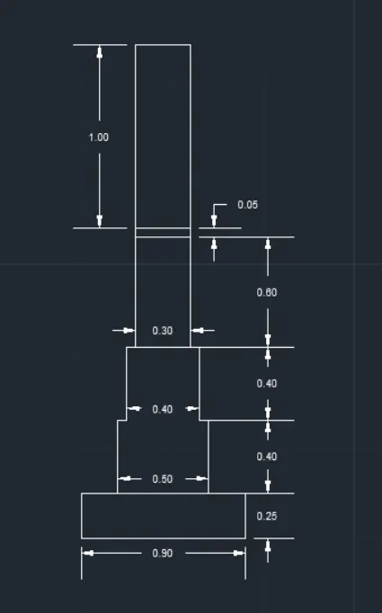
Step 5:
1. Type 'Line' or 'L' command in the command box and press Enter
2. Specify the midpoint of the previous line (l.e, 0.30 line) and draw a line horizontally with a 0.05 distance
3. Select the Offset command and give offset distance
as 0.15
4. Select the previous line (ie., 0.05 line) and offset both
sides of that line.
5. Select the Offset command again and give the offset
distance as 0.05
6. Select the below line and offset to the +y direction
7. Now select the Trim command and trim the unnecessary lines and edges
Step 6:
1. Type 'Line' or 'L' command in the command box and
press Enter
2. Specify the midpoint of the previous line (i.e., 0.30 line with 0.05) and draw a line horizontally with a 1.0 distance 3. Select the Offset command and give offset distance
as 0.15
4. Select the previous line (ie., 1.0 line) and offset both sides of that line.
5. Select the Offset command again and give the offset
distance as 1.0
6. Select the below line and offset to the +y direction
7. Now select the Trim command and trim the
unnecessary lines and edges
Step 7:
1. Type 'Line' or 'L' command in the command box and
press Enter
2. Specify the first point as the corner point of the line
(i.e., 0.30 line) at a distance of 1.5 from the below
3. Now specify the second point as 1.15 distance in -X
direction
4. Now specify the third line as 0.15 distance in the -Y
direction and
5. Now specify the last point as 1.15 distance in +X
directions and close the line command
6. Now Select the Line command again and specify the starting point as the corner point of the previous line and give distance as 0.15
7. Now close the line command and select Offset
command and give offset distance as 0.30 and offset
that previous line in +X direction 8. Now select Line command again and specify starting
point as 0.30 in +X direction 9. Specify the second point as 0.15 in +Y direction
10. Specify the third point as 0.30 in +X direction
11. Specify the fourth point as 0.15 in +Y direction
12. Now specify the last point as 0.30 in +X direction and close the command
13. Give the dimensions as per the drawing using the Dimension command in the command box.
RESULT:
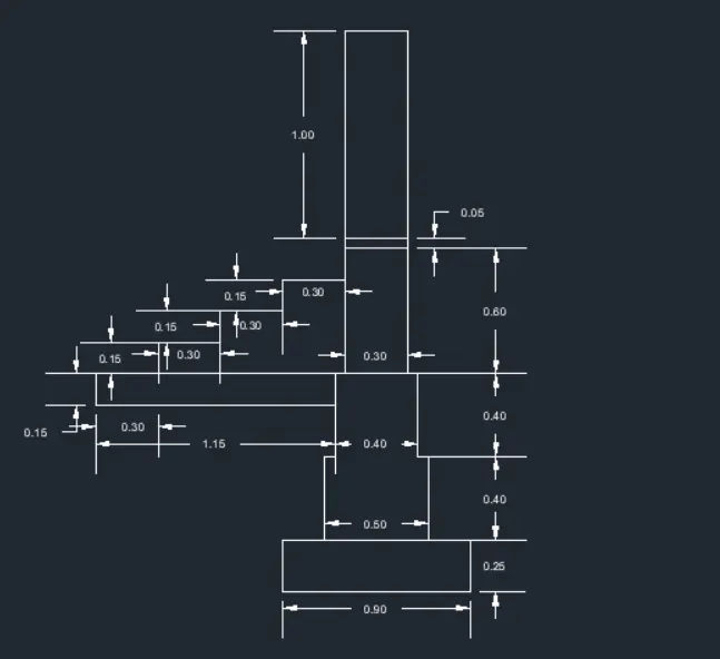
C.S OF LOAD BEARING WALL OVER SPREAD FOOTING
2. CROSS-SECTION OF ISOLATED FOOTING:
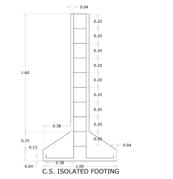
Commands Used:
1. Rectangle
2. Chamfer
3. Line
4. Offset
Step by Step Procedure:
Step 1:
1. Type 'Rectangle' or 'REC' In the command box and
press Enter
2. Specify first corner point as 1,1
3. Specify the length of the rectangle as 1.0
4. Specify the width of the rectangle as 0.40
Step 2:
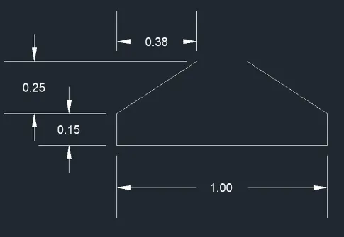
1. Type 'CHA' or 'CHAMFER' in the command box and
press Enter
2. Select D for Distance Option
3. Specify first chamfer distance as 0.25
4. Specify second chamfer distance as 0.38 5. Select the left and top line of the rectangle and it will
be chamfered
6. Repeat the same for the right and bottom lines of the rectangle.
7. Select the Trim command and trim the top line
Step 3:
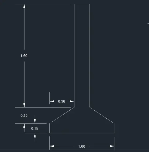
1. Type 'Line' or 'L' command in the command box and
press Enter
2. Specify the start point and draw a line along the +Y
axis with a 1.60 distance
3. Specify the next point as 0.24 along the +x axis 4. Specify the last point as 1.60 along -Y-axis and close the line command.
Step 4:
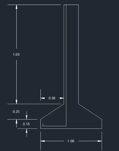
1.Type 'Line' or 'L' command in the command box and press
2.Enter Select the top line and specify the point at a distance of 0.04 and specify the starting point as 1.96 along -Y axis
4. Specify the next point as 0.38 along the -X-axis 5. Specify the last point as 0.04 along the +Y axis and then close the line command
Step 5:
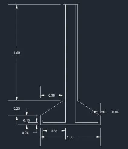
1. Type 'Line' or 'L' command in the command box and
press Enter
3. Select the top line and specify the point at a distance of 0.16 and specify the starting point as 1.96 along -Yaxis
4. Specify the next point as 0.38 along the +x axis 5. Specify the last point as 0.04 along the +Y axis and then close the line command
Step 6:
1. Select Offset by typing 'O' or 'Offset' on the command box and press Enter.
2. Specify the value of offset distance as 0.20
4. Select the top line and offset that line into equal 8 divisions from the top to the bottom 9. Give the dimensions as per the drawing using
the Dimension command in the command box.
RESULT:
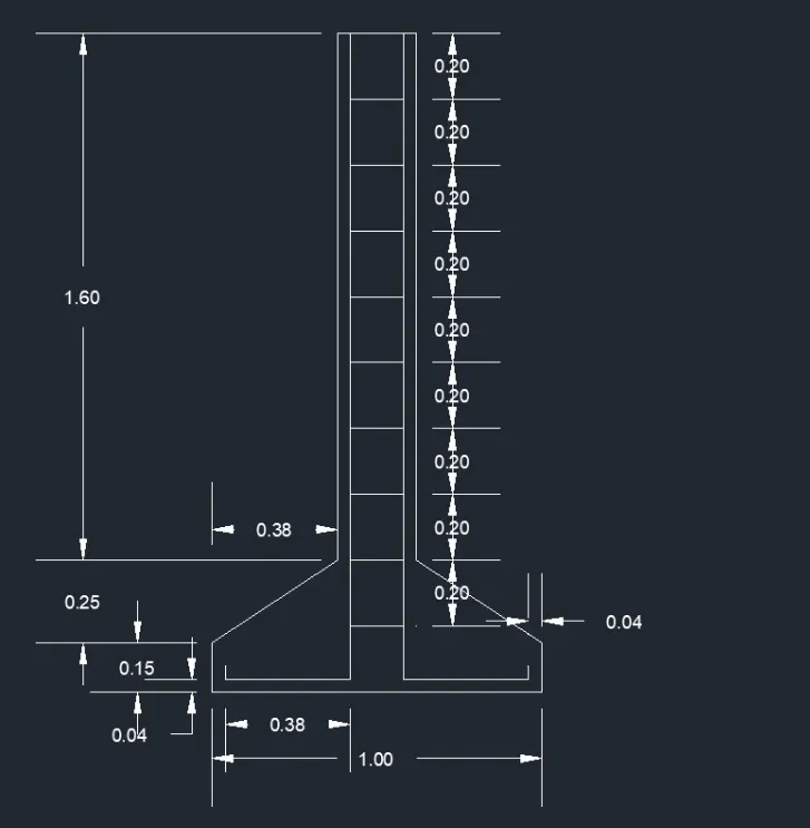
C.S OF ISOLATED FOOTING
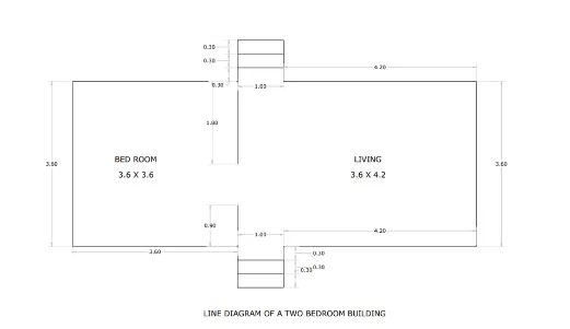
3. LINE DIAGRAM OF A TWO-BEDROOM BUILDING:
Commands Used:
1. Line
2. Offset
3. Trim
4. Dimension
5. Text
Step by Step Procedure:
Step 1:
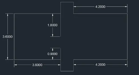
1. Type 'Line' or 'L' command in the command box and press Enter
2. Specify the starting point of the line as 1,1
3. Specify the next point as @3.60,0
4. Specify the next point as @1.0.0
5. Specify the next point as @4.20,0
6. Specify the next point as @0,3.60
7. Specify the next point as @4.20,0
8. Specify the next point as @1.0,0
9. Specify the next point as @3.60,0 and click 'C' to close the command
10. Select the Line command and specify the starting point at a distance of 3.60 from the start point
11. Specify the next point as @0,0.90 and click 'C' to close
the command
12. Select the Line command and specify the starting point on the top line at a distance of 3.60 from the start point
13. Specify the next point as @0,-1.80 and click 'C' to
close the command
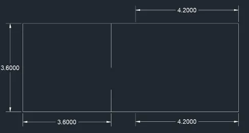
Step 2:
1. Trim the lines in the middle of the top and bottom line to create staircases
2. Give the dimensions as per the drawing using the
Dimension command in the command box
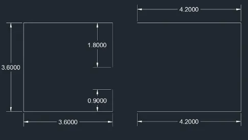
Step 3:
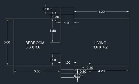
1. Type 'Line' or 'L' command in the command box andr Pess Enter
2. Select the Line command and specify the starting
point at a distance of 3.60 from the start point 3. Specify the next point as @0,-0.9
4. Specify the next point as @1,0
5. Specify the last point as @0,0.9 and close the line Command
6. Type 'Line' or 'L' command in the command box and
press Enter
7. Select the Line command and specify the starting point on the top line at a distance of 3.60 from the start point
8. Specify the next point as @0,0.9
9. Specify the next point as @1,0
10. Specify the last point as @0,-0.9 and close the line
Command
Step 4:
1. Type 'offset' or 'O' command in the command box and
press Enter 2. Specify offset distance as 0.30
3. Select the below line at the bottom section and create offset lines at a distance of 0.30
4. Do the same procedure for the top line at the top section to create offset lines
Step 5:
1. Give the dimensions as per the drawing using the Dimension command in the command box
2. Type Text in the command box and press Enter
3. Give the text as bedroom dimensions and living room dimensions as per drawing
RESULT:
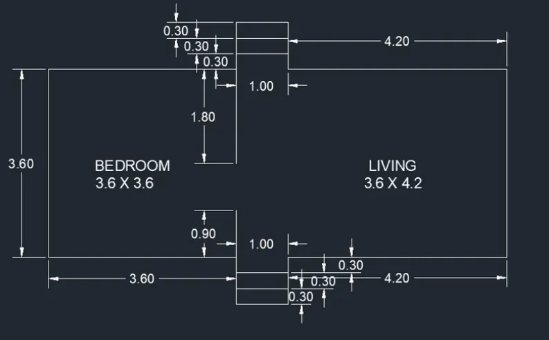
LINE DIAGRAM OF A TWO BEDROOM BUILDING
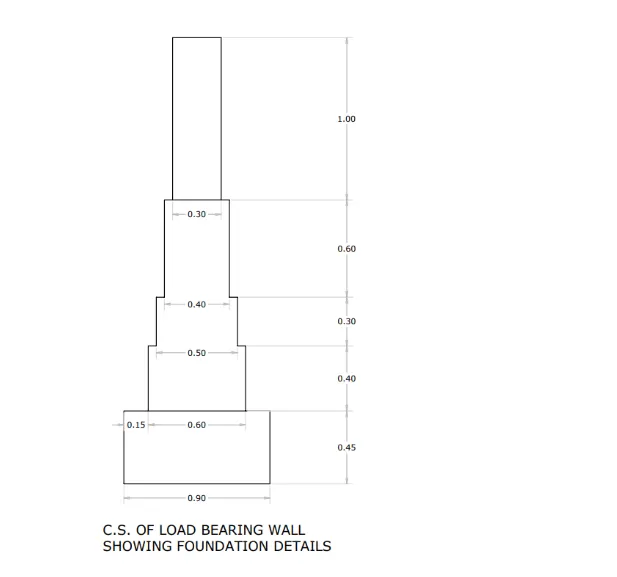
4.CROSS-SECTION OF LOAD-BEARING WALL SHOWING FOUNDATION DETAILS:
Commands Used:
1. Rectangle
2. Line
3. Offset
4. Trim
5. Dimension
Step by Step Procedure:
Step 1:
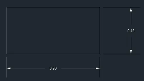
1. Type 'Rectangle' or 'REC' In the command box and
press Enter
2. Specify first corner point as 1,1
3. Specify the length of the rectangle as 0.9
4. Specify the width of the rectangle as 0.45
Step 2:
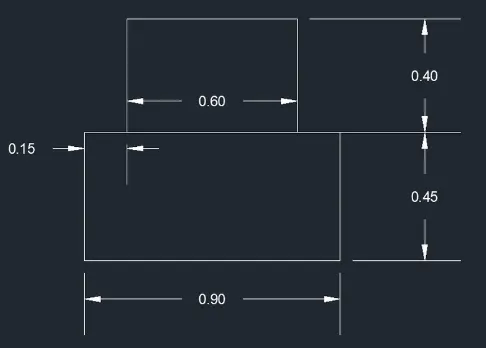
1. Type 'Line' or 'L' command in the command box and
press Enter
2. Specify the midpoint of the rectangle and draw a line
horizontally with 0.40
3. Select the Offset command and give offset distance
as 0.30
4. Select the previous line (ie., 0.40 line) and offset both sides of that line.
5. Select the Offset command again and give the offset distance as 0.40
6. Select the below line and offset to the +Y direction
7. Now select the Trim command and trim the
unnecessary lines and edges
Step 3:
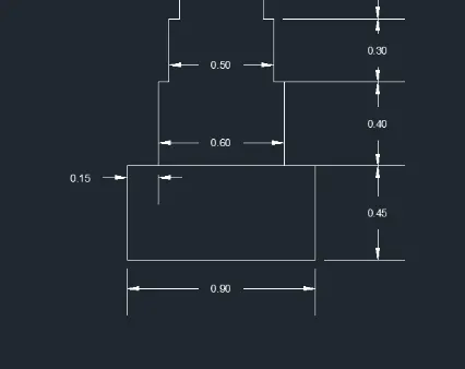
1. Type 'Line' or 'L' command in the command box and press Enter 2. Specify the midpoint of the previous line (l.e., 0.60 line)
and draw a line horizontally with a 0.30 distance
3. Select the Offset command and give offset distance
as 0.25
4. Select the previous line (i.e., 0.30 line) and offset both
sides of that line. 5. Select the Offset command again and give the offset distance as 0.30
6. Select the below line and offset to the +Y direction
7. Now select the Trim command and trim the
unnecessary lines and edges
Step 4:
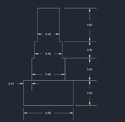
1. Type 'Line' or 'L' command in the command box and
press Enter
2. Specify the midpoint of the previous line (ie, 0.40 line) and draw a line horizontally with a 0.60 distance
3. Select the Offset command and give offset distance
as 0.20
4. Select the previous line (ie., 0.60 line) and offset both
sides of that line.
5. Select the Offset command again and give the offset distance as 0.60
6. Select the below line and offset to the +Y direction
7. Now select the Trim command and trim the
unnecessary lines and edges
Step 5:
1. Type 'Line' or 'L' command in the command box and press Enter
2. Specify the midpoint of the previous line (i.e., 0.40 line) and draw a line horizontally with a 1.0 distance 3. Select the Offset command and give offset distance
as 0.15 4. Select the previous line (ie., 1,0 line) and offset both sides of that line.
5. Select the Offset command again and give the offset
distance as 1.0
6. Select the below line and offset to the +Y direction 7. Now select the Trim command and trim the unnecessary lines and edges.
RESULT:
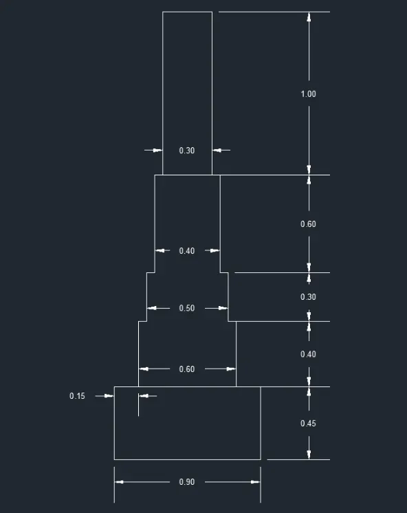
C.S OF LOAD BEARING WALLS SHOWING FOUNDATION DETAILS
5. ISOMETRIC VIEW OF STEPS
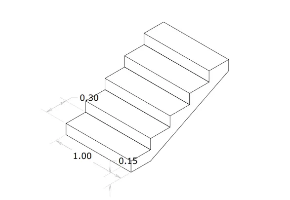
Commands Used:
1. Drafting Settings
2. Polyline
3. Line
4. Copy
Step by Step Procedure:
Step 1:
1. Type 'DS' in the command box and press Enter
2. Turn on 'Isometric Snap' in the status bar. This will active the isometric screen
3. Type 'Polyline' in the command box and enter
5. Specify the starting point as 1,1 or by clicking randomly on screen by using the cursor
6. Take isoplane left
7. Specify the next point as 1.0 pointing cursor towards
NW direction
8. Take isoplane right.
9. Specify the next point as 0.15 pointing cursor towards
North direct 10. Specify the next point as 1 pointing cursor towards
the southeast direction
11. Specify the last point as 0.15 pointing cursor towards East direction
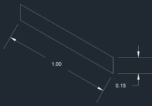
Step 2:
1. Type 'Polyline' in the command box and press Enter
2. Specify the start point
3. Take isoplane top
4. Specify the next point as 0.30 pointing cursor towards
North-East direction
5. Specify the next point as 1.0 pointing cursor towards
northwest direction 6. Specify the last point as 0.30 pointing cursor towards southwest direction
Step 3:
1. Type 'co' or 'Copy' in the command box and press
Enter
2. Select the complete step and copy it and press enter
3. Select a base point and place it randomly at each point
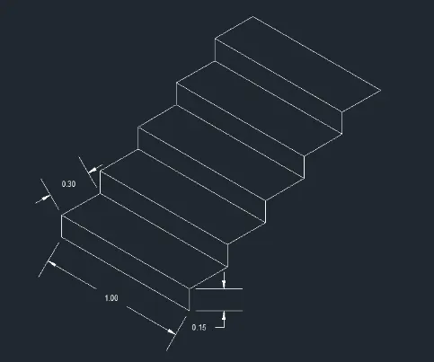
Step 4:
1. Type Line or 'L' in the command box and press Enter.
2. Specify the starting point above the right corner of the
top step
3. Take isoplane right
4. Specify the next point as 0.15 pointing towards the South direction 5. Type 'Line' or 'L' in the command box and press Enter
6. Specify the starting point below the right corner of the bottom step
7. Take isoplane right
8. Specify the next point as 0.30 pointing cursor towards North-East direction
9. Type 'Line' or 'L' in the command box and press Enter
10. Join the Line from bottom point to top point
11. Give the dimensions as per the drawing using
Dimensionthe command in the command box
RESULT:
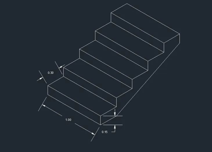
ISOMETRIC VIEW OF STEPS
Part 6. ISOMETRIC VIEW OF GABLE WALL
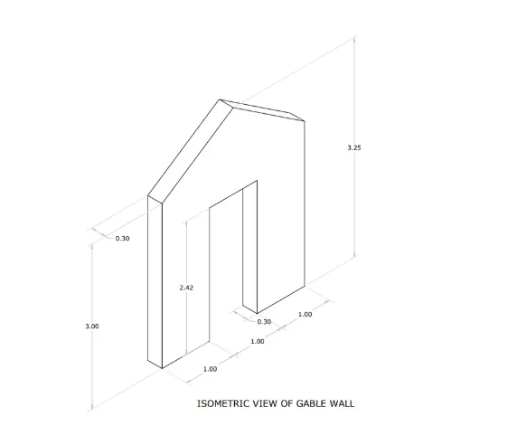
Commands Used:
1. Drafting Settings
2. Line
3. Trim
4. Dimension
Step by Step Procedure:
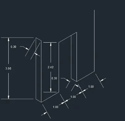
Step 1:
1. Type 'DS' in the command box and press Enter
2. Turn on Isometric Snap in the Status bar. This will
activate the isometric screen
3. Type 'L' in the command line and press Enter 4. Specify the start point by clicking the cursor on the screen
5. Take isoplane left and specify the next point as 0.30
pointing cursor towards northwest direction
6. Specify the next point as 3.0 pointing the cursor
towards the North direction
7. Specify the next point as 0.30 pointing the cursor
towards the southeast direction
8. Specify the next point as 3.0 pointing the cursor
towards the East direction
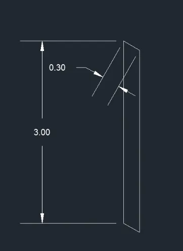
Step 2:
1. Type 'L' in the command box and press Enter
2. Specify the bottom right corner and Take Isoplane top
3. Specify the next point as 1.0, pointing the cursor towards the North-East direction
4. Specify the next point as 1.0, pointing the cursor
towards the North-East direction
5. Specify the next point as 1.0, pointing the cursor
towards the North-East direction
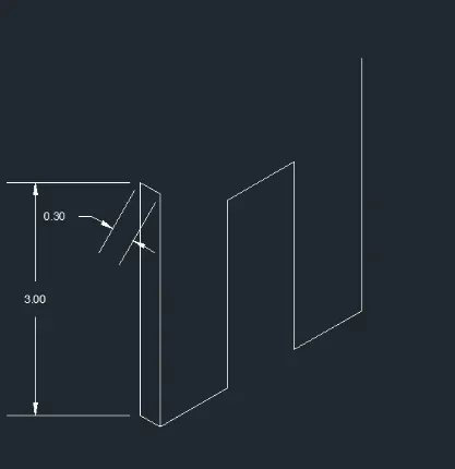
Step 3:
1. Trim the unnecessary bottom line
2. Type 'L' in the command box and press Enter 3. Specify the start point on the previous line
4. Take isoplane right and specify the next point as 2.42, pointing the cursor towards the North direction
5. Take isoplane top and specify the next point as 1.0,
pointing the cursor towards the North-East direction
6. Specify the next point as 2.42, pointing the cursor
towards the East direction. 7. Type Line command in the command box and press Enter
8. Specify the start point and take Isoplane left
9. Specify the next point as 0.30, pointing the cursor
towards the northwest direction
10. Take isoplane right and specify the next point as 2.12, pointing the cursor towards North Direction
11. Type 'L' in the command box and press Enter
12. Specify the start point at the bottom corner of the line 13. Take isoplane top and specify the next point as 1.5, pointing the cursor towards North-East direction
14. Take isoplane right and specify the next point as 3.25,
pointing the cursor towards the North direction 15. Type 'L' in the command box and press Enter
16. Specify the start point at the top right corner on the previous line
17. Take the isoplane left and specify the next point as 0.30, pointing the cursor towards the northwest direction.
Step 4:
1. With ortho off, draw a line between the corner of the left side and the projected line
2. Draw it to the other side also till it meets the right
corner
3. Draw the vertical line with ortho on @0.3 and join the vertical line using a line from left and right end same
4. Remove unwanted lines by using Erase.
5. Now give the dimensions as per the drawing using the Dimension command in the command box
RESULT:
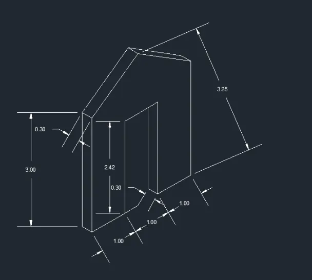
ISOMETRIC VIEW OF GABLE WALL
Conclusion :
Created a floor plan,footing detail and isometric view using AutoCAD and had good understanding of tools like rectangle polylines, isometric views,snap mode,offset mode,copy,move and ortho mode.