Modelling of 25 storey building with the specified properties using ETABS
1. Aim: To model a 25 storey building on E-tabs with structural properties as in the given question.
Introduction: To model a 25 storey building on E-tabs with structural properties as in the given question.
Procedure:
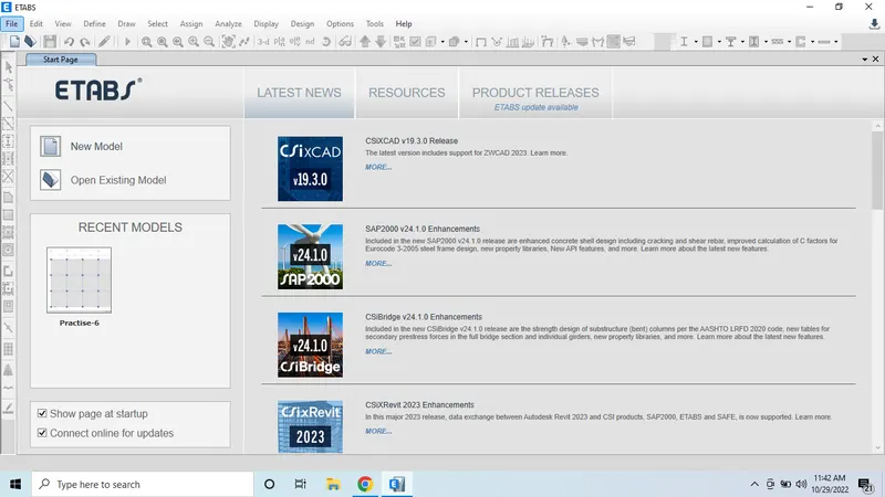
- Open the Etabs software and select the New model option.
- Select the settings option and change
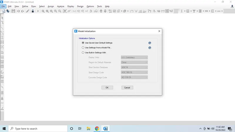
- Select the settings option and select the units related to the drawing.
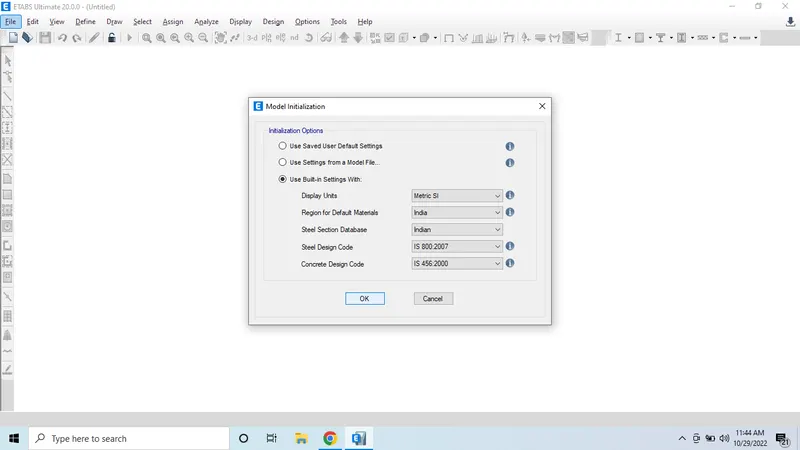
- Then New tab will appear on the screen.
- Now select the custom grid and story data option.
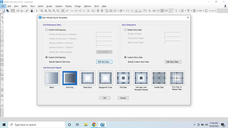
- Then the dialogue box will get open.
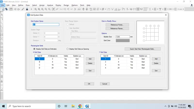
- Change the grid data ordinates as per the grids given in the question.
- Then click ok.
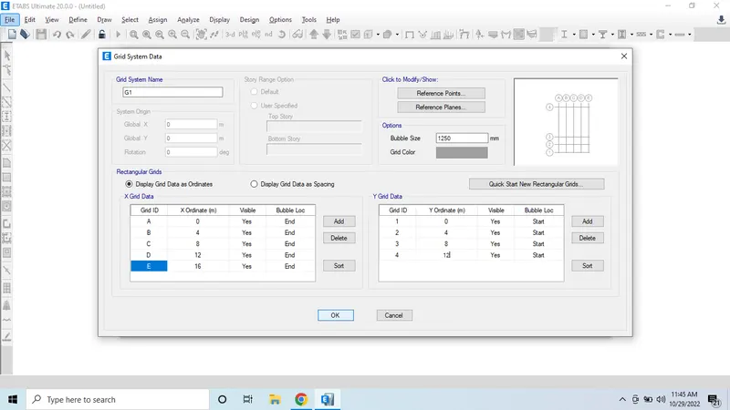
- Now select the Edit story data option.
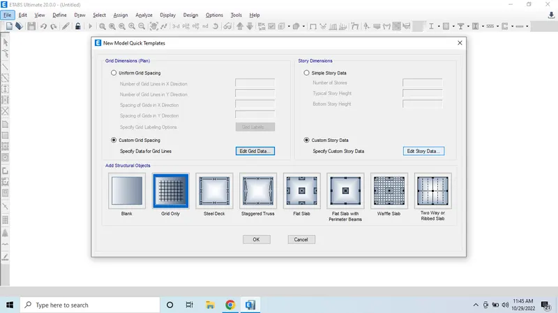
- Change the story otions as per the required floors.
- Then make the master story floor as first floor.
- Now make the siliar floor to first floor for the remaining floors.
- The plinth height should be 1.3 as per the given question and remaining floor heights should be 3m.
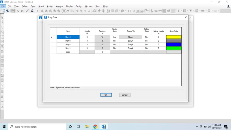
- Now as per the given question, we need 25storeys of building.
- Then click the right cick and we get the options to add the story.
- Select the add story option.
- And select the Keep existing story height option.
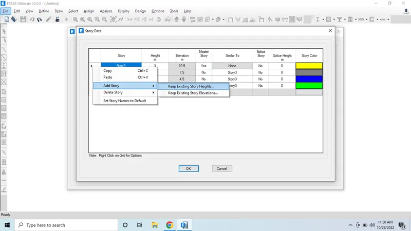
- Then we can see the dialogue box open.
- In that select the number of storeys to be added and click ok.
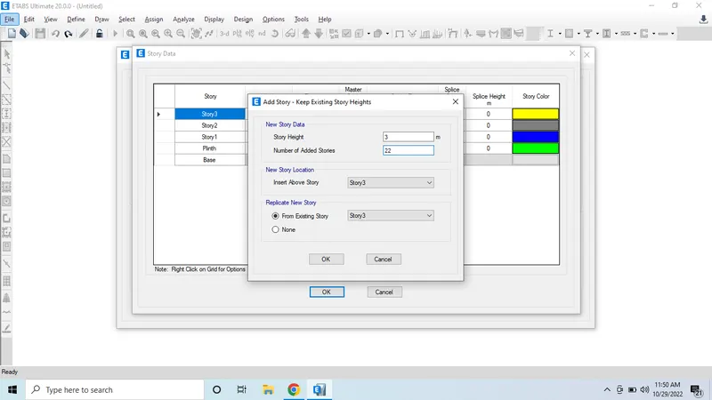
- Now we can see the total 25 stories floor options.
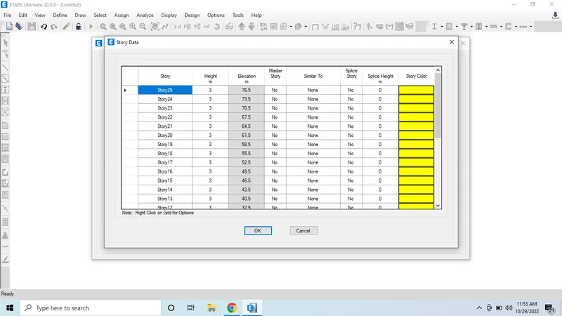
- Change the 25story as roof.
- Then click ok.
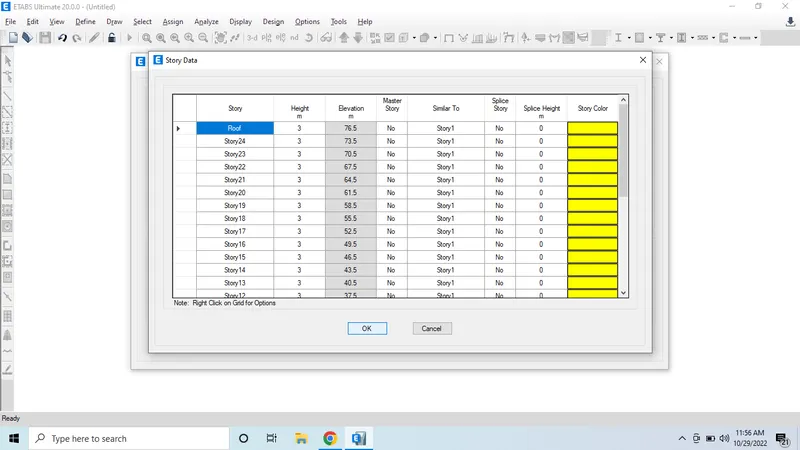
- Then click ok.
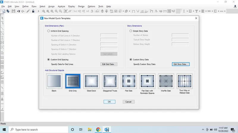
- Now we can see the page open and grids open in the drawing.
- There are 2 views open in the drawing as plan and elevation views.
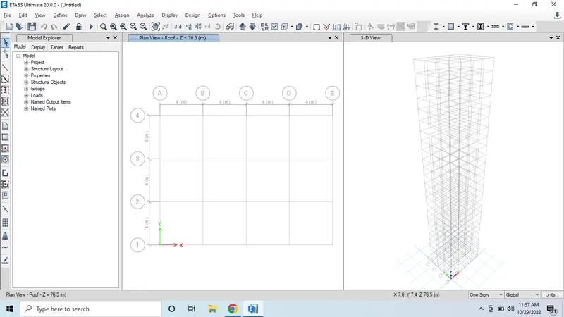
- Go to define option and apply material properties to te grids.
-
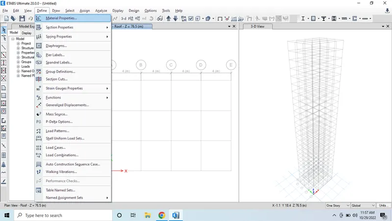
- Click on the add new material option.
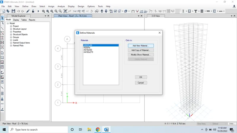
- Then add the concrete material with the grade of M30 as in the given question.
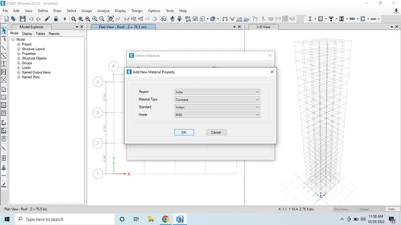
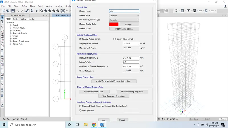
- Then change the mateial name as M30 and click ok.
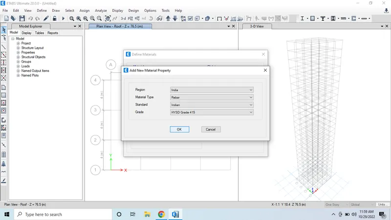
- Now add the another material as rebar for HYSD grade 415 and click ok.
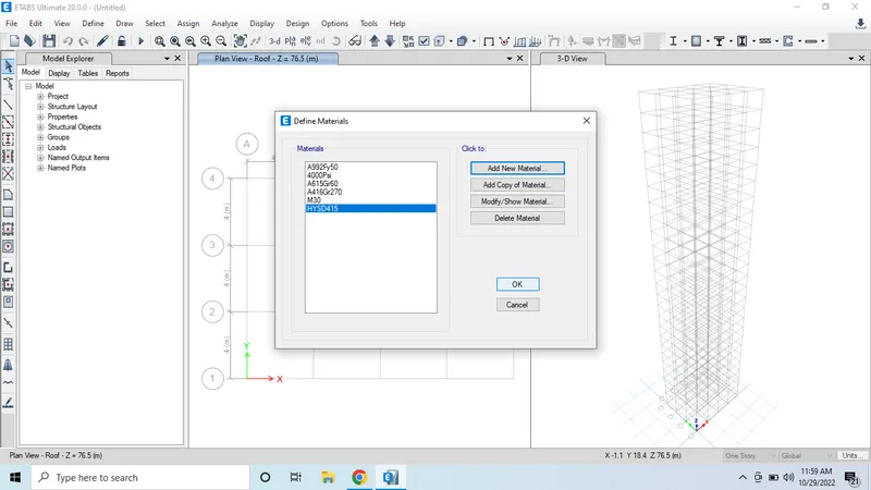
- Now we can see the 2 materials added and click ok.
- Now go to the define option and select the section properties option and select frame section for creating beams and columns.
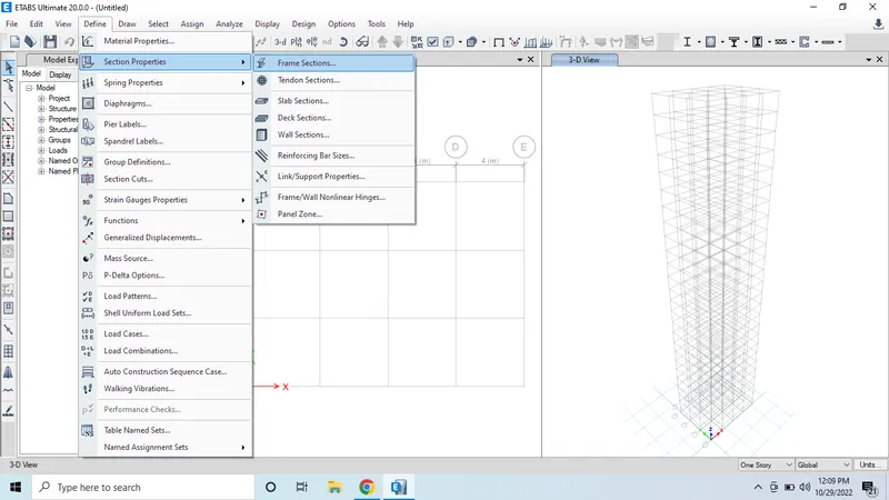
- Select Add new property option.
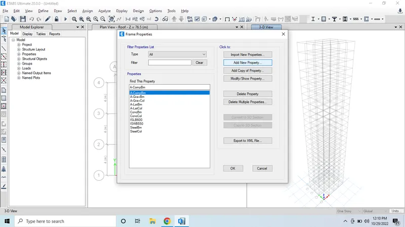
- Then select the beam in the concrete option.
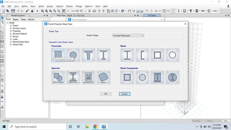
- After selecting a dialogue box will appear.
- Now give the property name as beam a=with size given in the question.
- And change the material property.
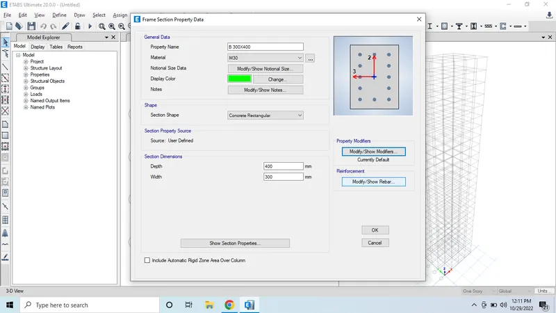
- Now click on the modify/show rebar option.
- Then select the M3 design for beam and click ok.
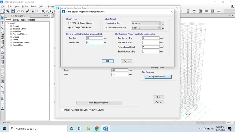
- Now we can the beam size property.
- We have to add column property in the same way.
- Click on add new property.
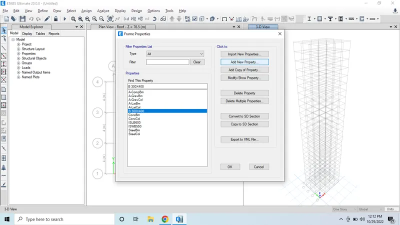
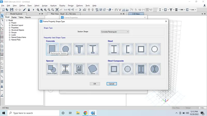
- Select concrete option for columns.
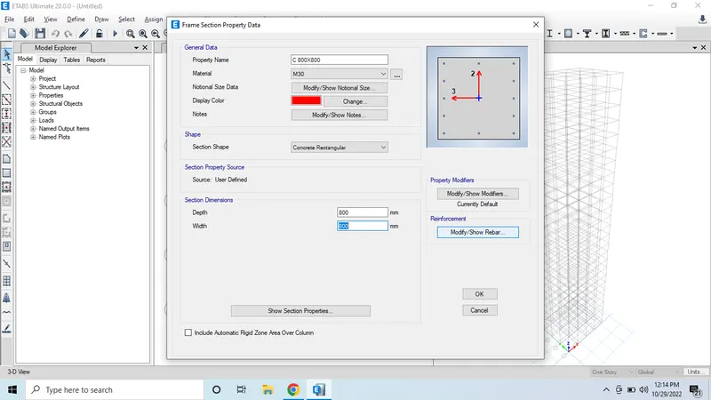
- Mention column size as in the given question and select the material as M30.
- Then give the section dimensions as depth and width.
- Now click on modify/rebar option.
- Select column design type and give the valies for longitudinal and confinement bars.
- Then click ok.
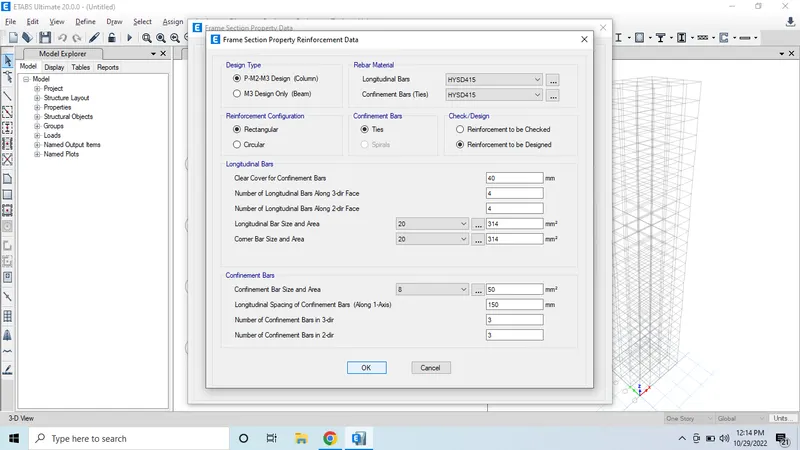
- Now we can see the both beam and column placed in the property.
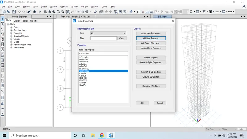
- In the same way select slab section option.
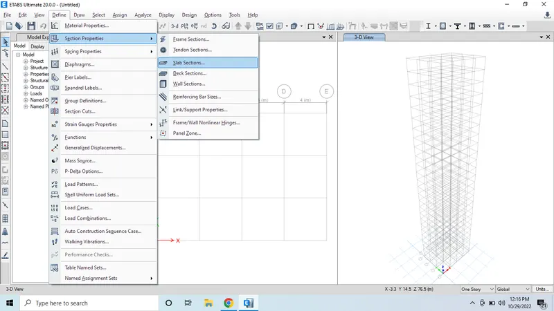
- Click on Add new property option.
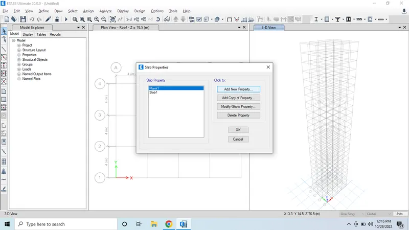
- Select the property name as slab 150 and slab material as M30.
- Then give the slab thickness and click ok.
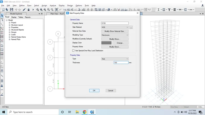
- Now we can see the slab name option.
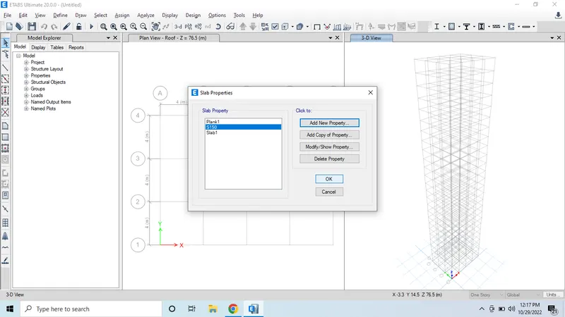
- Noe go to the define option and select load pattern option.
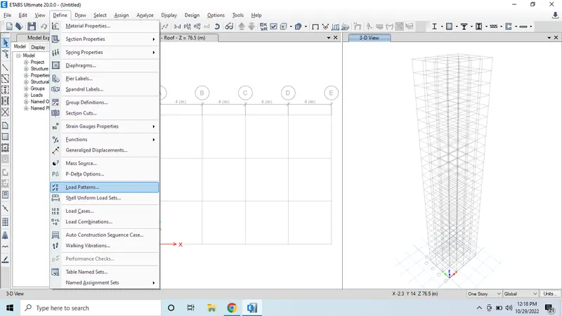
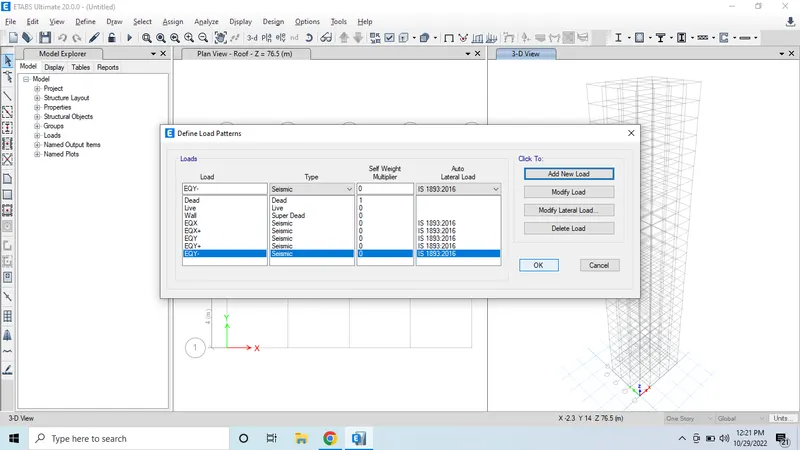
- Then a dialogue box wil appear on the screen.
- Now click on the add new load and give the loads which are existing in the strucure.
- Then click ok.
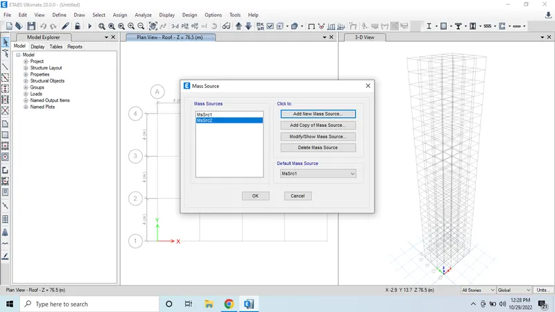
- Now select Mass source option in the define tab.
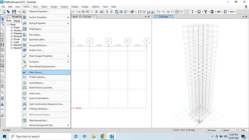
- Now we can see all the loads which are given in the load cases.
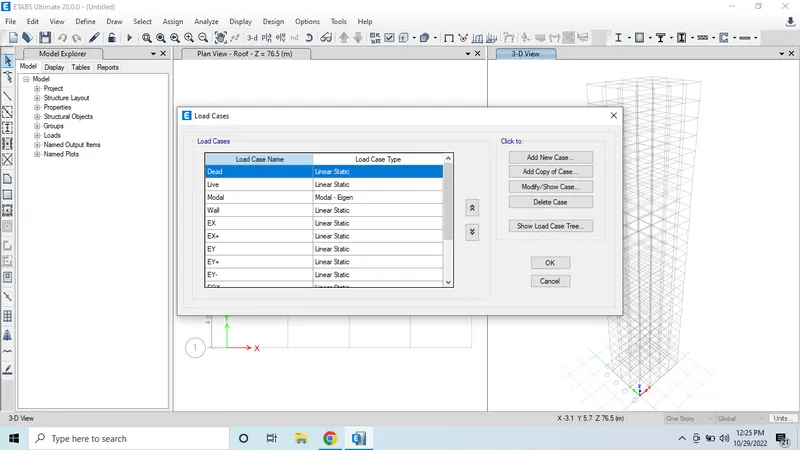
- Now select the Mass source option.
- Select add new source option.
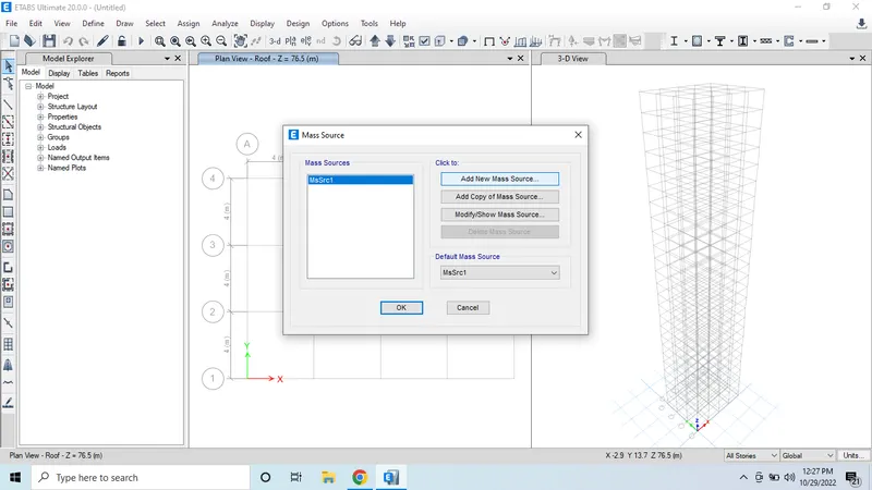
- Add the loads for dead load, live load and wall for load pattern.
- Click ok.
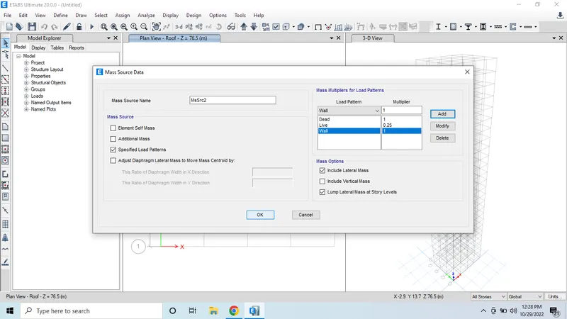
- Now we can see the new mass source which we have created.
- Now select quick draw column option.
- Select column size property.
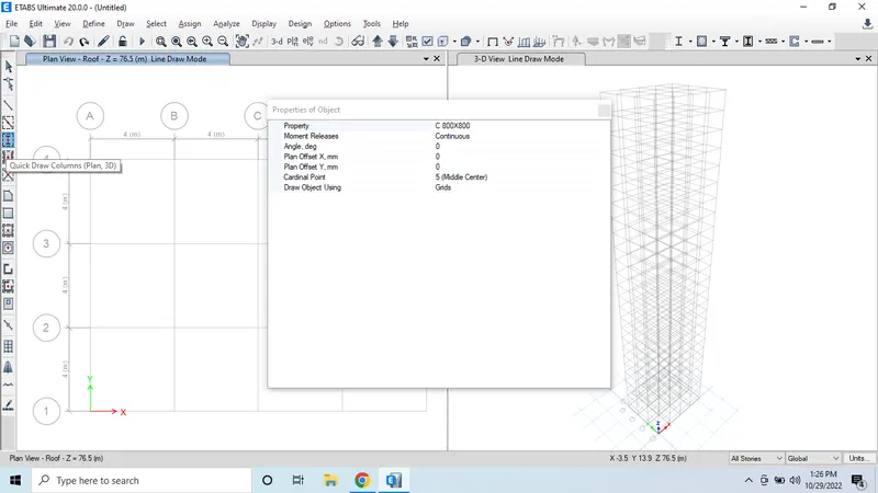
- Now apply the column to the grids.
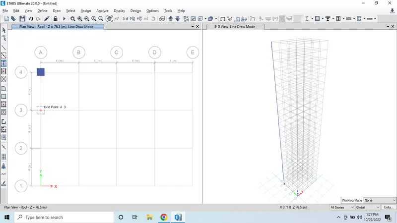
- by using the option replicate we can easily apply the cloumns.
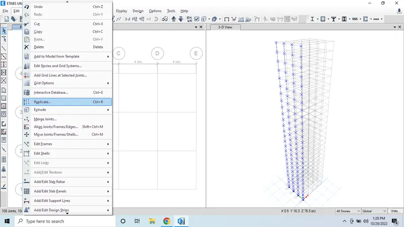
- A dialogue box will appear on the screen.
- Give the proper values and click ok.
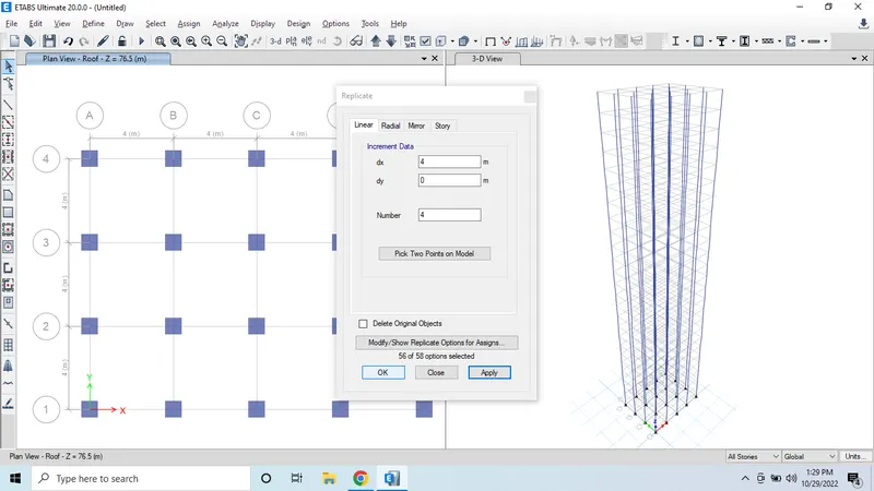
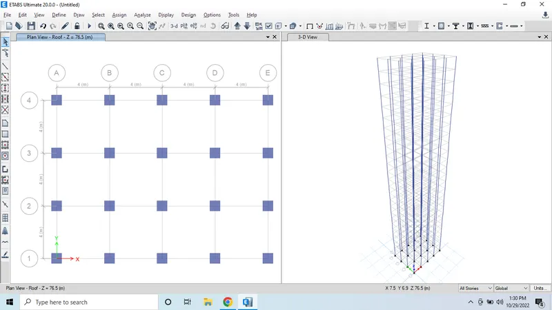
- Now we can see the columns given to the grids.
- Now select the beam option as in the property option.
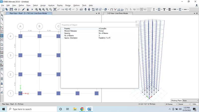
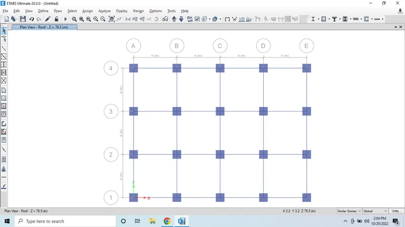
- Now we can get all the beams applied to the grids.
- Now select the slab option from the options.
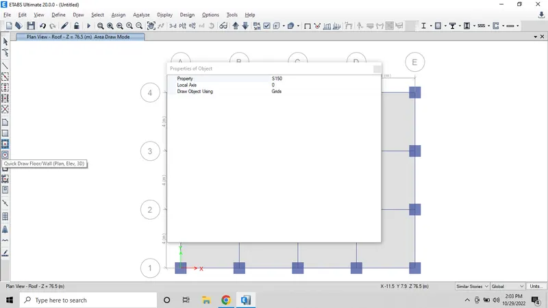
- select the slab area in the grids.
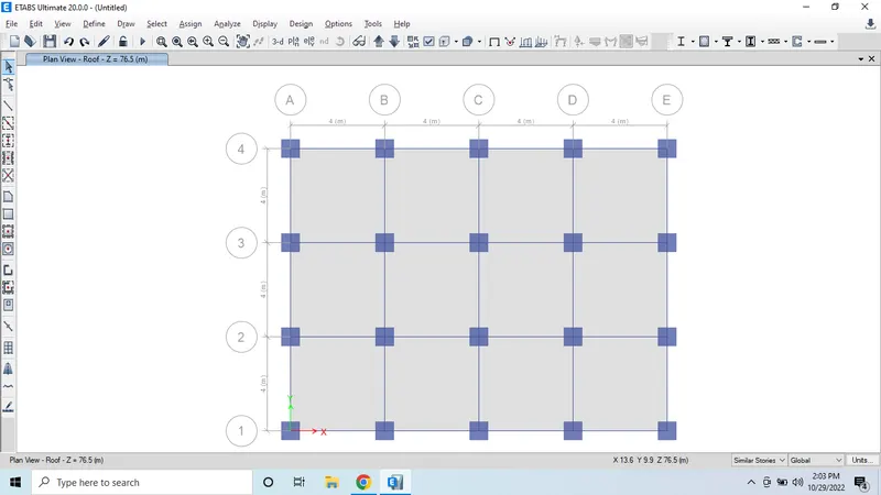
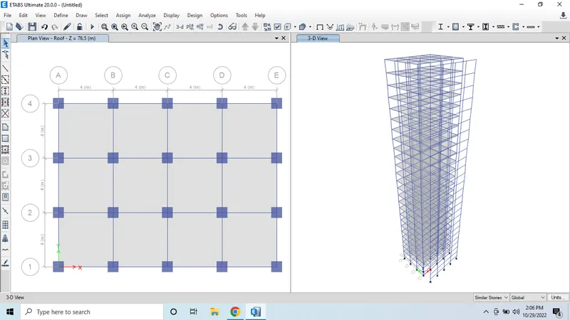
- Now we can see the slabs applied on the grids in the plan view and 3d view.
- Now we have to select all the beams for that go to the select option and select frame section in the properties.
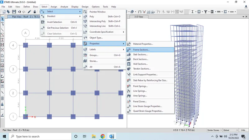
- Select beam size.
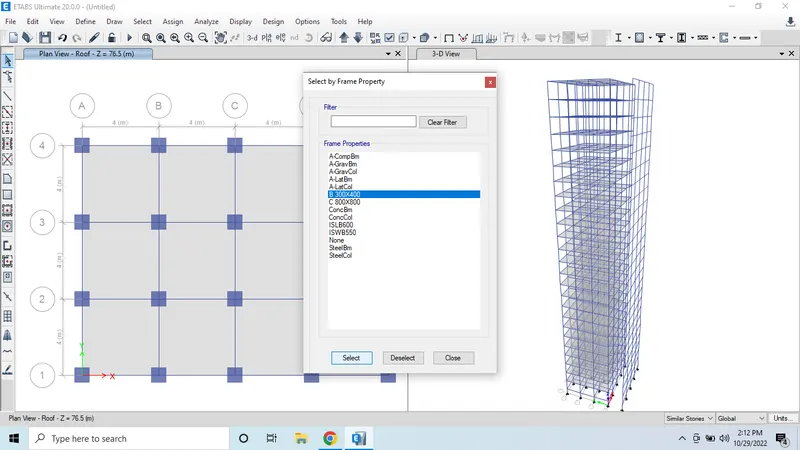
- Now we can see all the beams are selected.
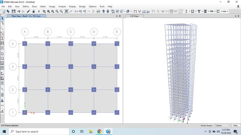
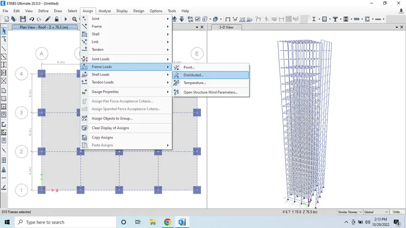
- Then assign the loads and select the frame loads and apply distributed load to the beams.
- Apply the load as wall and give the load as 10kn/m.
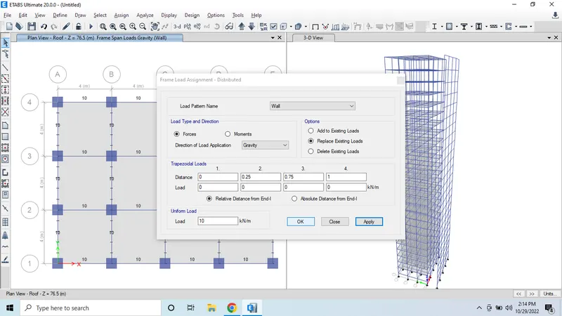
- Now we can see the load applied on the grids.
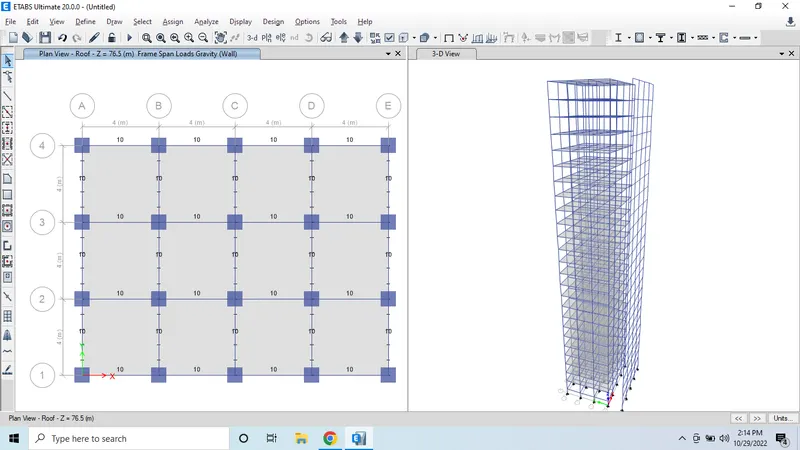
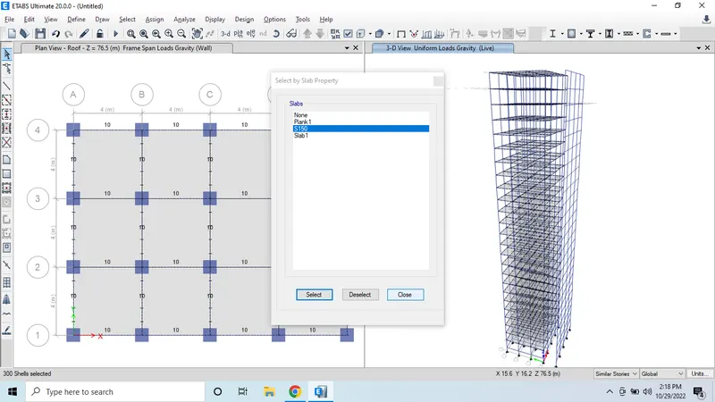
- In the same way select slab section option.
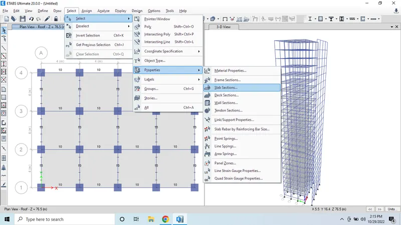
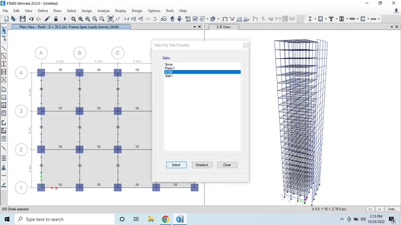
- Select S150 option.
- Apply uniform loads to the slabs.
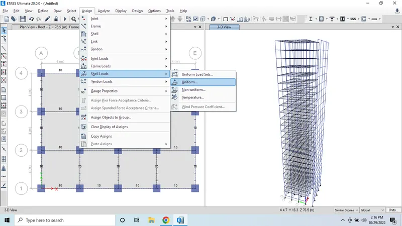
- Give the load as 3 which is in the given question.
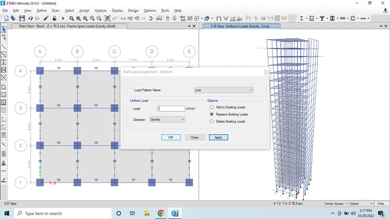
- Select the slab 150 portion and click Ok.
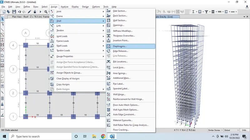
- Now give diaphragms option to the slabs.
- Now select d1 option.
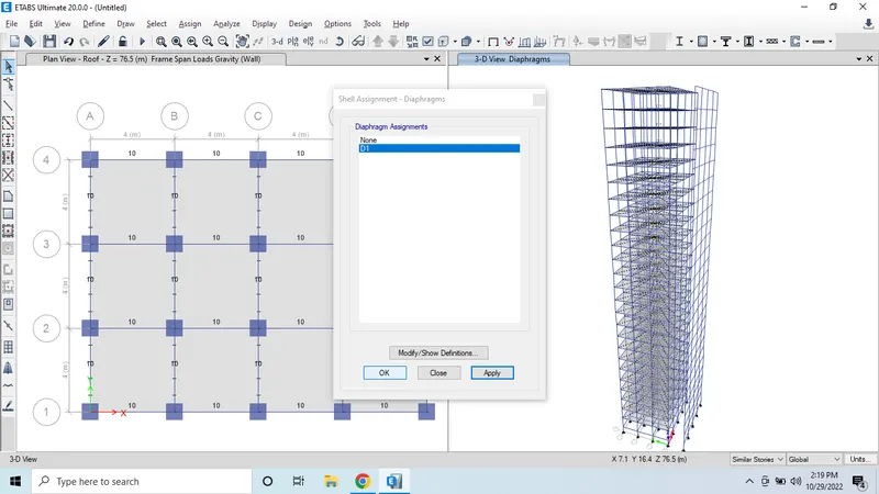
- we can see the diapgram applied to the grids.
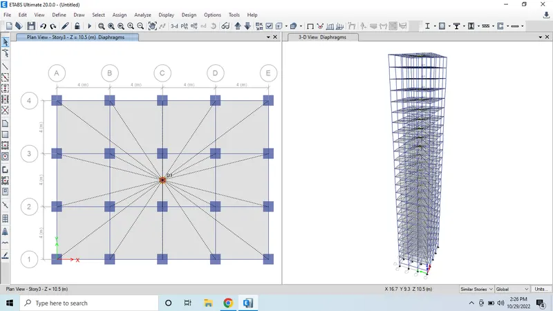
- Now click on run analysis option.
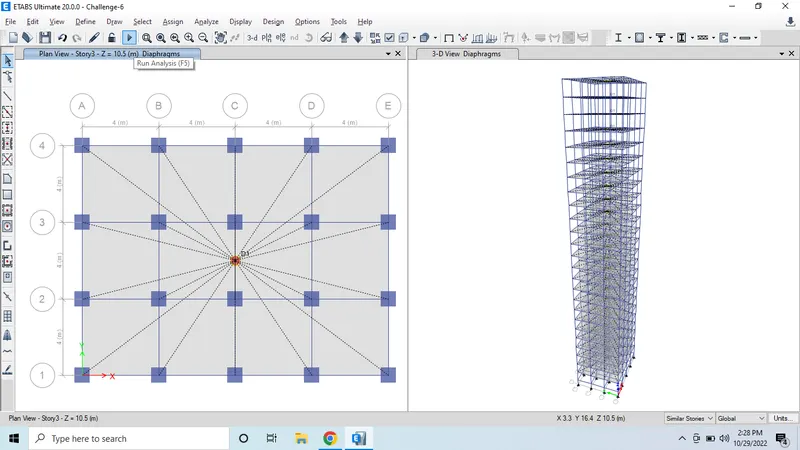
- then we can see the process going.
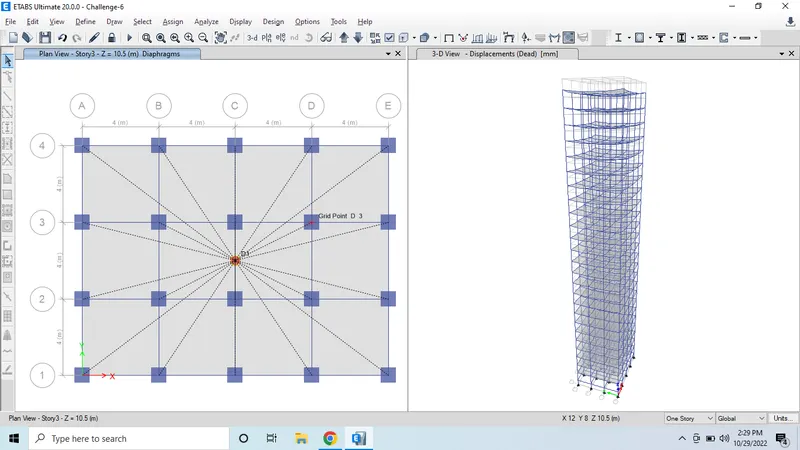
- Select display option and select show table option.
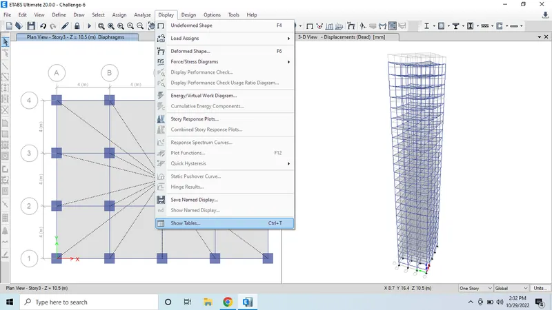
- Select the structure option table.
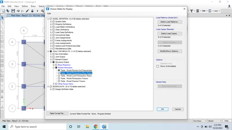
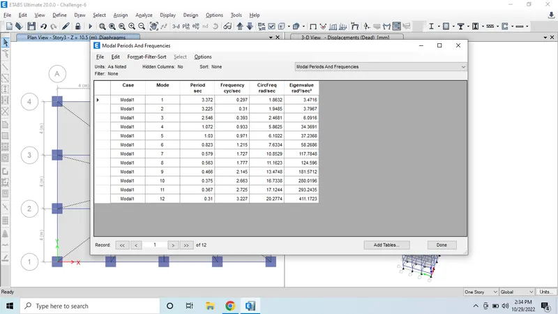
- Now we can see the table for modal periods.
- Now select modal load participation rations.
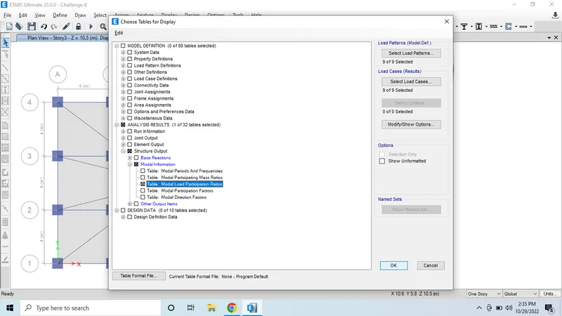
- Now we can see the table.
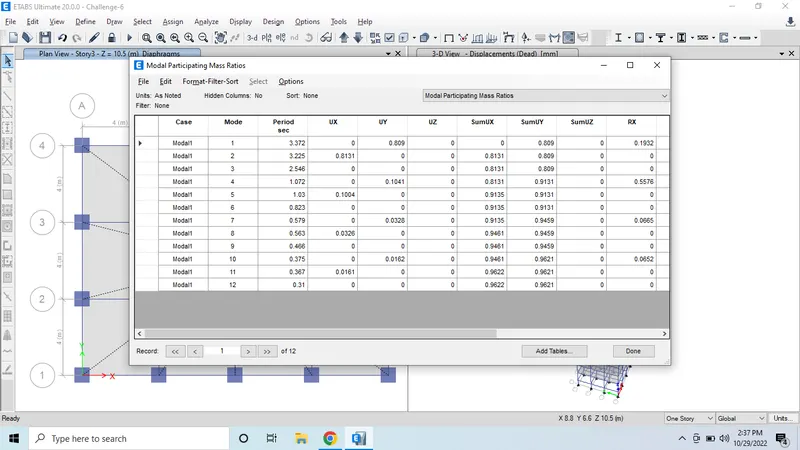
Result:
- For fundamental Translational natural period in the x-direction and exercise resut is 4.41
- Torsional irregularity in Y-direction and exercise result is 4.22
- For vertical irregularity as per IS 1893-2016(part-1) table-6 exercise result for first three modes is yes.
- For vertical irregularity as per IS 1893-2016(part-1) table-6 exercise result for fundamental lateral natural periods in tw principal plane directions are away from each way is no.
- For Inter storey drift exexercise result is no.