Modelling of 25 storey building with the specified properties using ETABS
Ans:-
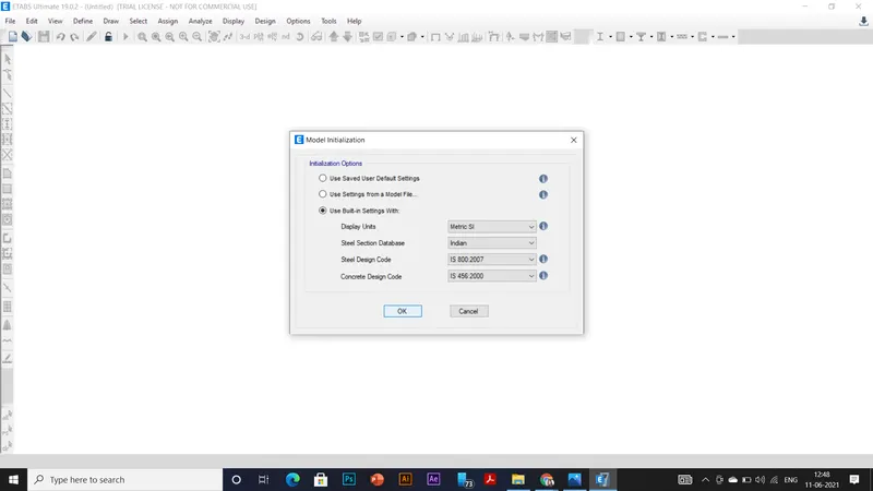
- open etabs and click on file, new model.
- in the pop-up set the display units and remaining parameters as shown in the figure.
- then click on ok.
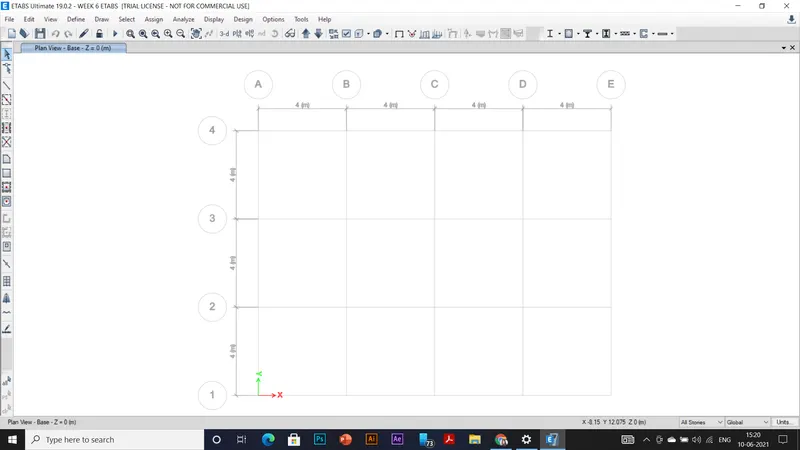
- In the grid settings , select the required number of bays ,and other parameters.
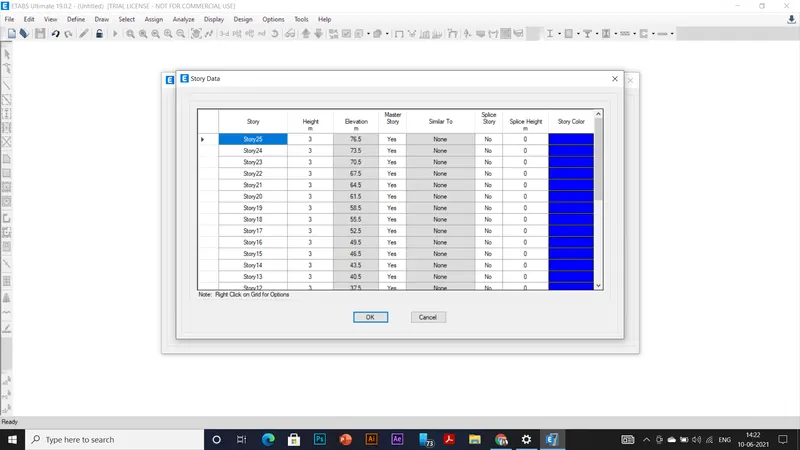
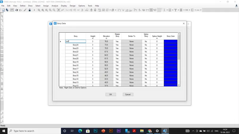
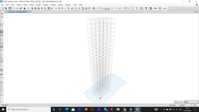
- then click on the custom storey data , add the required number of storey in the pop up.
- from 1st storey to 25th storey , they are similar storeys.
- take height 3m for each floor, plinth height 1.5m.
- then click on ok.
- then click define and select the material properties.
- in the pop up select add new materials.
- now select the region and material type.
- in the new pop up add the requirements .
- similarly , define redars materials.
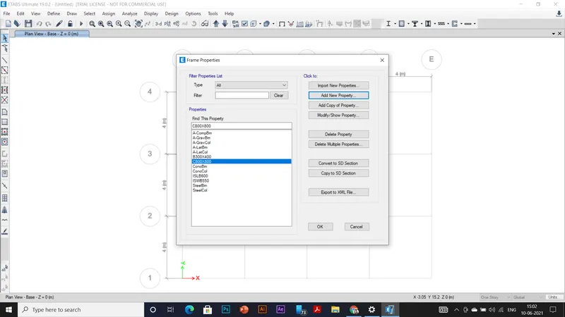
- now in menu bar select the section properties and select the frame sections.
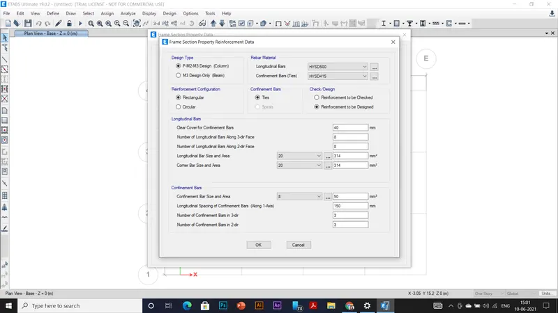
- add new property, select the desired cross section , next add all the required properties.
- nect select its lngitudinal and the confinement bars .
- similarly , do this process for the column sections also.
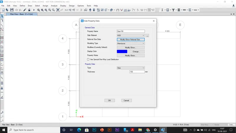
- in the section properties ,now design the slab section.
- add the new property , select the modelling type as the membrane.
- provide the thickness, then click on ok.
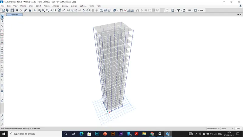
- select the quick draw columns,and place columns at the grid points for all the storeys.
- and select the quick draw beams for all storeys.
- similarly select the quick draw slabs for all similar storeys.
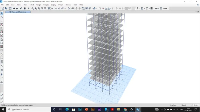
- next for 1 storey select the grids and click on assign and click joint and restraints.
- select the point supports, assign for the grid points.
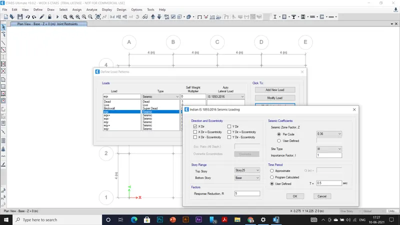
- adding the load pattens,in the definne select the load patterns, click on add new load and add all the required loads with the required properties.
- next click on the modify lateral loads, for every load mannage the required parameters and save , click on ok.
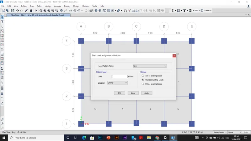
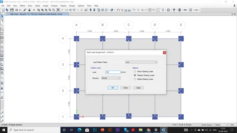
- assign the shell and uniform loads,
- here we take live load of 3kn/m2 for all the floors rather than 1.5kn/m2 for the 25th floor.
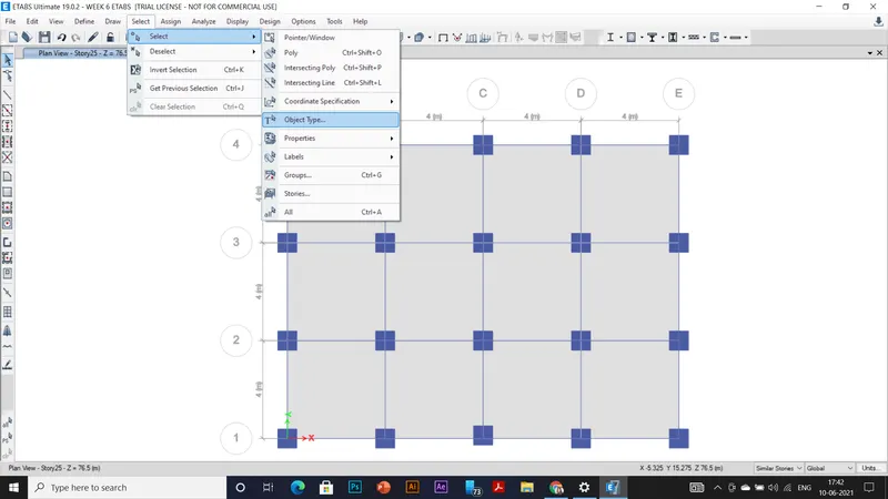
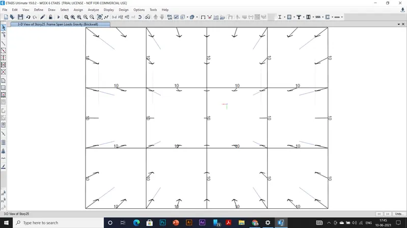
- now select all the beams by select by object type option ,next from assign select the frame loads and distributed.
- select load patterns and add load.
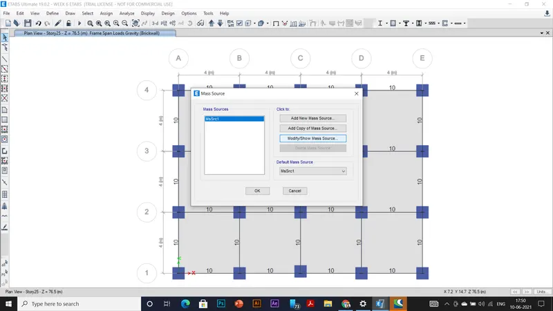
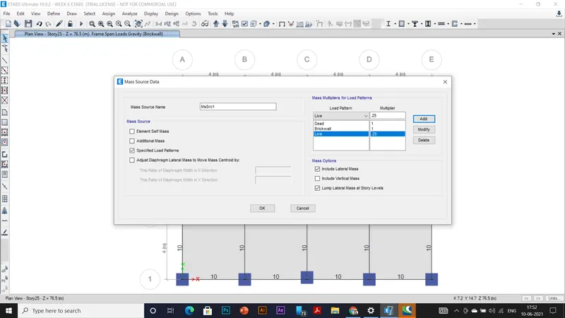
- in define select the mass source and modify.
- add the load patterns.
- next in define select the load combinations, add the default design combo.
- select the concrete frame design ,by select object type and select the floors.
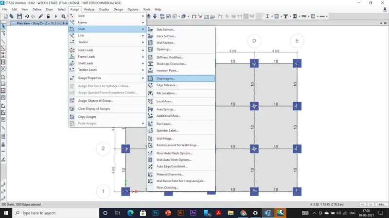
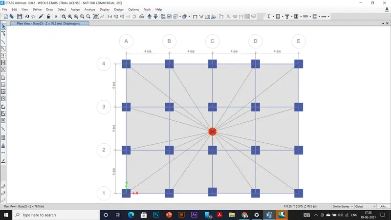
- in the assign select the shell.diaphrams,modify and apply.
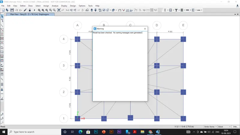
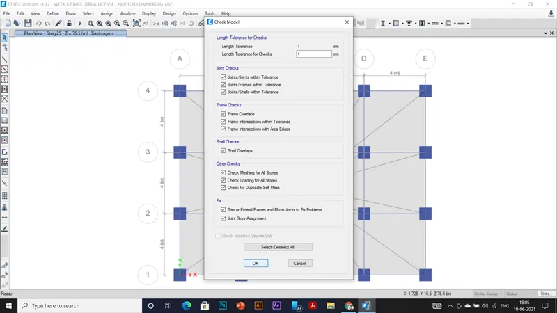
- next in the analyze click on the check model and check the all the checks, click on ok.
- now go to design mode select the joints of the number 21 and delect , then again check the model.
- next in the analysis run the model.
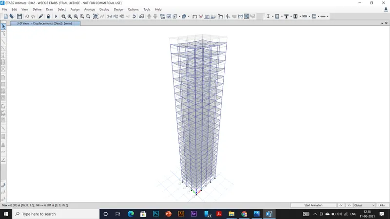
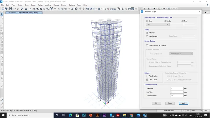
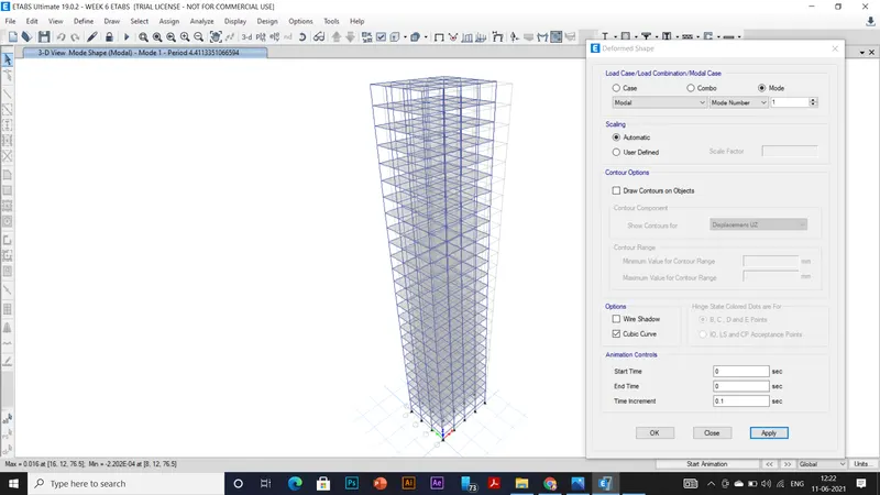
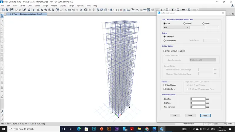
- go to display>deformed shape, deformed shape will be displayed for any particular loads.
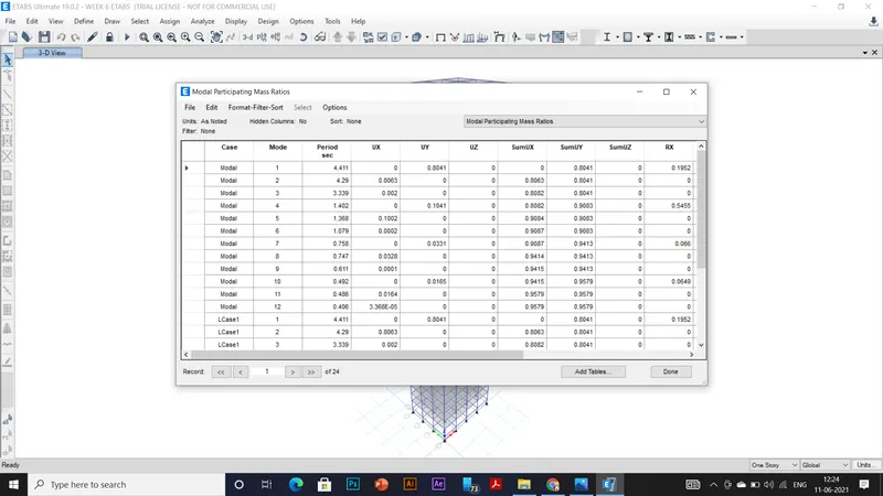
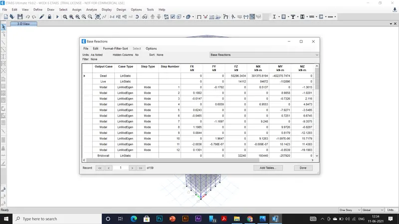
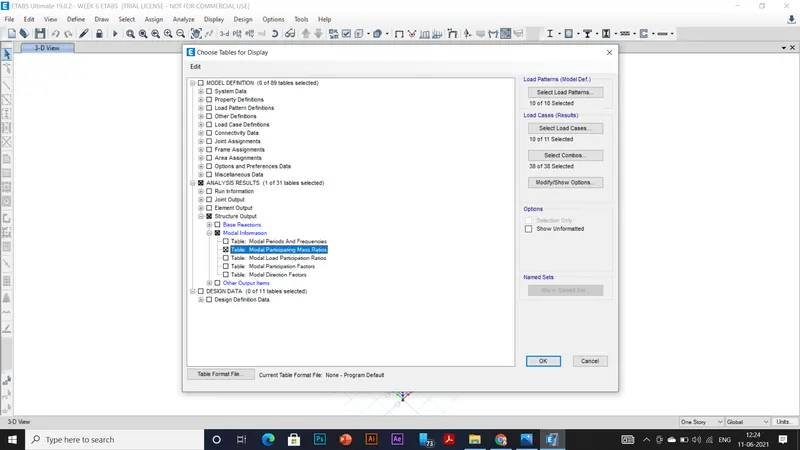
- go to display and click on show tables, select the modal participating mass ratio as shown in the in figure .
- the modal participating mass ratio table has been visible.
Results:-